Srne ASF4880SH3 User manual
File version: V1.0
Solar Storage Inverter
User Manual
Product Models
ASF4880SH3
ASF48100SH3
ASF48120SH3

File version: V1.0
CONTENTS
1.
Safety
......................................................................................................................................................................................................................................... 1
1.1 How to use this manual.................................................................................................................................................................... 1
1.2 Symbols in this manual..................................................................................................................................................................... 1
1.3 Safety instruction................................................................................................................................................................................1
2. Production Instructions ..........................................................................................................................................................................................................2
2.1 Instructions .......................................................................................................................................................................................... 2
2.2 Features ...............................................................................................................................................................................................2
2.3 System connection diagram ............................................................................................................................................................ 3
2.4 Production overview.......................................................................................................................................................................... 4
3. Installation ..................................................................................................................................................................................................................................5
3.1 Select the mount location.................................................................................................................................................................5
3.2 Mount the inverter..............................................................................................................................................................................6
3.3 Remove terminal protection cover and dust screen................................................................................................................... 6
4. Connection.................................................................................................................................................................................................................................7
4.1 Three-phase mode ............................................................................................................................................................................ 7
4.2 Cable & circuit breaker requirement...............................................................................................................................................9
4.3 AC input & output connection....................................................................................................................................................... 10
4.4 Battery connection...........................................................................................................................................................................11
4.5 PV connection.................................................................................................................................................................................. 11
4.6 Dry contact connection...................................................................................................................................................................12
4.7 Grounding connection.....................................................................................................................................................................12
4.8 Final assembly ..................................................................................................................................................................................12
4.9 Start-up the inverter........................................................................................................................................................................12
5. Operation.................................................................................................................................................................................................................................13
5.1 Operation and display panel .......................................................................................................................................................... 13
5.2 Setting................................................................................................................................................................................................17
5.3 AC output mode...............................................................................................................................................................................24
5.4 Battery charging mode ................................................................................................................................................................... 25
5.5 Time-slot charging/discharging function .....................................................................................................................................27
5.6 Battery parameter............................................................................................................................................................................28
6. Communication......................................................................................................................................................................................................................30
6.1 Overview............................................................................................................................................................................................30
6.2 USB-B port........................................................................................................................................................................................30
6.3 WIFI port............................................................................................................................................................................................31
6.4 RS485 / CAN port............................................................................................................................................................................31
6.5 Dry contact port ............................................................................................................................................................................... 32
7. Fault and Remedy................................................................................................................................................................................................................ 33
7.1 Fault code ......................................................................................................................................................................................... 33
7.2 Troubleshooting................................................................................................................................................................................35
8. Protection and Maintenance.............................................................................................................................................................................................37
8.1 Protection function.......................................................................................................................................................................... 37
8.2 Maintenance..................................................................................................................................................................................... 39
9. Datasheet ................................................................................................................................................................................................................................ 40
File version: V1.0
1
This chapter contains important safety instructions. Read and keep this manual for future reference.
Be sure to comply the local requirements and regulation to install this inverter.
Beware of high voltage. Please turn off the switch of each power sources before and during the
installation to avoid electric shock.
For optimal operation of this inverter, select the appropriate cable size and the necessary protective
devices as specified.
Do not connect or disconnect any connections when the inverter working.
Do not open the terminal cover when the inverter working.
Make sure the inverter is well grounding.
Be careful not to cause short-circuiting of the AC output and DC input.
Do not disassembly this unit, for all repair and maintenance, please take it to the professional service
center.
Never charge a frozen battery.
1.
Safety
1.1 How to use this manual
•
This manual contains important information、guidelines、operation and maintenance for the following
products : ASF series 4880SH3, 48100SH3, 48120SH3
•This manual must be followed during installation, use and maintenance.
1.2 Symbols in this manual
Symbols
Description
DANGER indicates a hazardous situations which if not avoided will result in
death or serious injury.
WARING indicates a hazardous situations which if not avoided could result
in death or serious injury.
CAUTION indicates a hazardous situations which if not avoided could result
in minor or moderate injury.
NOTICE provide some tips on operation of products.
1.3 Safety instruction
△
!
DANGER
△
!
CAUTION
△
!
DANGER
△
!
WARING
○
!
NOTICE
File version: V1.0
2
2. Production Instructions
2.1 Instructions
ASF H3 series is a new type of solar energy storage inverter control inverter integrating solar energy
storage & utility charging and energy storage, AC sine wave output. It adopts DSP control and
features high response speed, reliability, and industrial standard through an advanced control
algorithm.
2.2 Features
Supports lead-acid battery and li-ion battery connections.
With a dual activation function when the li-ion battery is dormant; either mains or photovoltaic
power supply access can trigger the activation of the li-ion battery.
Support three-phase pure sine wave output (350~415V).
Supports phase voltage adjustment in the range of 200, 208, 220, 230, 240Vac.
Supports two PV inputs, with the function of simultaneously tracking the maximum power charging
or carrying capacity of two MPPT.
Dual MPPT, efficiency
up to 99.9%, single maximum current of 22A, perfectly adapted to high-
power modules.
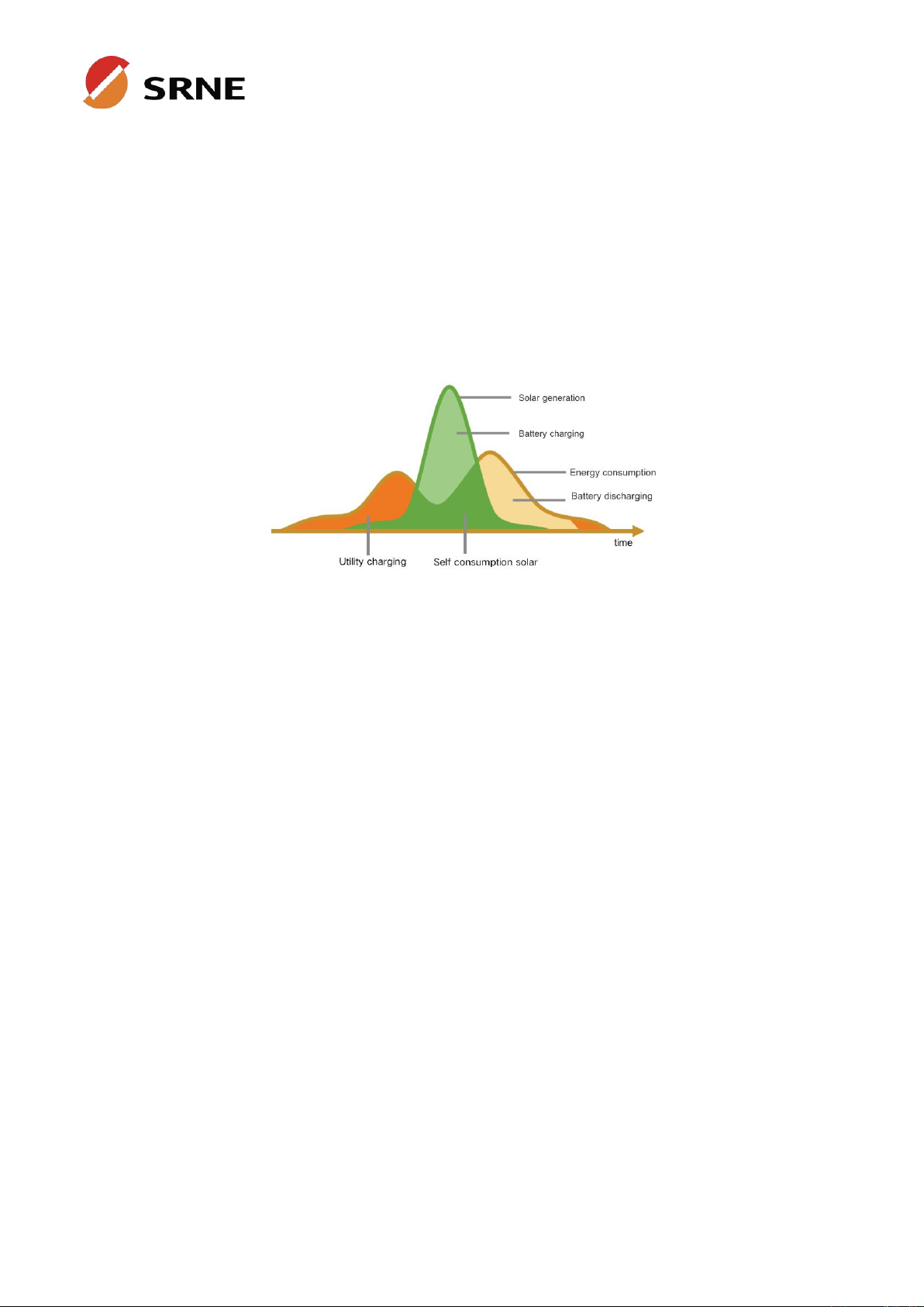
4 charging modes are available: solar only, mains priority, solar priority, and mixed mains and PV
charging.
With time-slot charging and discharging setting function, it helps users to take advantage of peak
and valley tariffs and save electricity costs.
Energy-saving mode function to reduce no-load energy losses.
With two output modes of utility bypass and inverter output, with uninterrupted power supply
function.
LCD large screen dynamic flow diagram design, easy to understand the system data and operation
status.
360° protection with complete short-circuit protection, over-current protection, over-voltage
protection, under-voltage protection, over-load protection, etc.
Support CAN, USB, and RS485 communication.
File version: V1.0
3
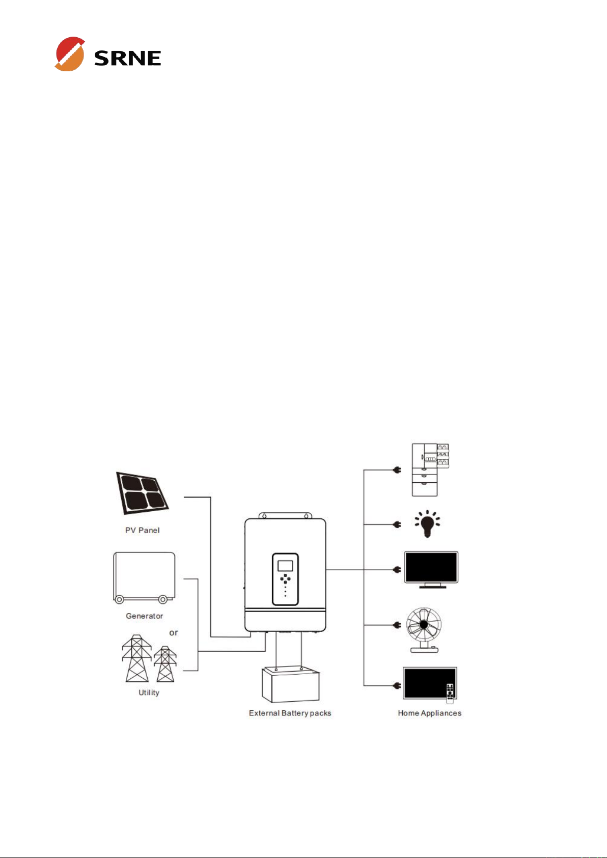
2.3 System connection diagram
The diagram below shows the system application scenario of this product. A complete system consists
of the following components:
1. PV modules:converts light energy into DC energy, which can be used to charge the battery via an
inverter or directly inverted into AC power to supply the load.
2. Utility grid or generator:connected to the AC input, either of the connected utility and generator can
charge the battery while supplying the load. When the batteries and photovoltaic modules supply the
load, the system can operate without the utility or generator.
3. Battery:The role of the battery is to ensure the normal power supply of the system loads in case of
insufficient photovoltaic and no utility power.
4. Home load:connects to a variety of home and office loads including refrigerators, lamps, TVs, fans,
air conditioners and other AC loads.
5. Inverter:it is the energy conversion device of the whole system.
The actual application scenario determines the specific system cabling.

File version: V1.0
4
2.4 Production overview
1
LCD screen
2
LED indicator
3
Touchable key
4
ON/OFF rocker switch
5
PV input (PV1+PV2)
6
Battery (positive)
7
Battery (negative)
8
Dry contact
9
RS485/CAN port
10
WIFI port
11
USB-B port
12
Grounding screw
13
AC output (L1+L2+L3 +N)
14
AC input (L 1+L2+L3+N)
15
AC input circuit breaker

File version: V1.0
5
Do not install the inverter near highly
flammable materials.
Do not install the inverter in a potentially
explosive area.
Do not install the inverter in a confined space
with lead-acid batteries.
Do not install the inverter in direct
sunlight.
Do not install or use the inverter in a
humid environment.
3. Installation
3.1 Select the mount location
ASF H3 series can be used outdoors (protection degree IP20). Please consider the followings before
selecting the location:
Choose the solid wall to install the inverter.
Mount the inverter at eye level.
Adequate cooling space must be provided for the inverter.
The ambient temperature should be between -10~55℃(14~131℉)to ensure optimal operation.
△
!
DANGER
△
!
CAUTION
File version: V1.0
6
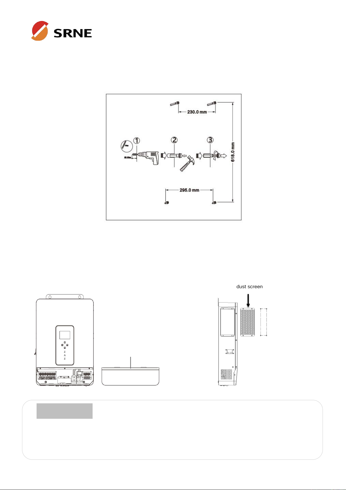
3.2 Mount the inverter
Drill 4 mounting holes in the wall with an electric drill according to the specified dimensions, insert 2
expansion screws above and 2 M5 screws below to fix the inverter.
3.3 Remove terminal protection cover and dust screen
Using a screwdriver, remove the terminal protection cover and dust screen.
When using the device in areas with poor air quality, the dust screen is easily blocked by air particles.
Please disassemble and clean the dust screen periodically to avoid affecting the internal air flow rate
of the inverter, which may trigger an over-temperature protection fault (19/20 fault) affecting the use
of the power supply and the service life of the inverter.
terminal protection cover
○
!
NOTICE
File version: V1.0
7
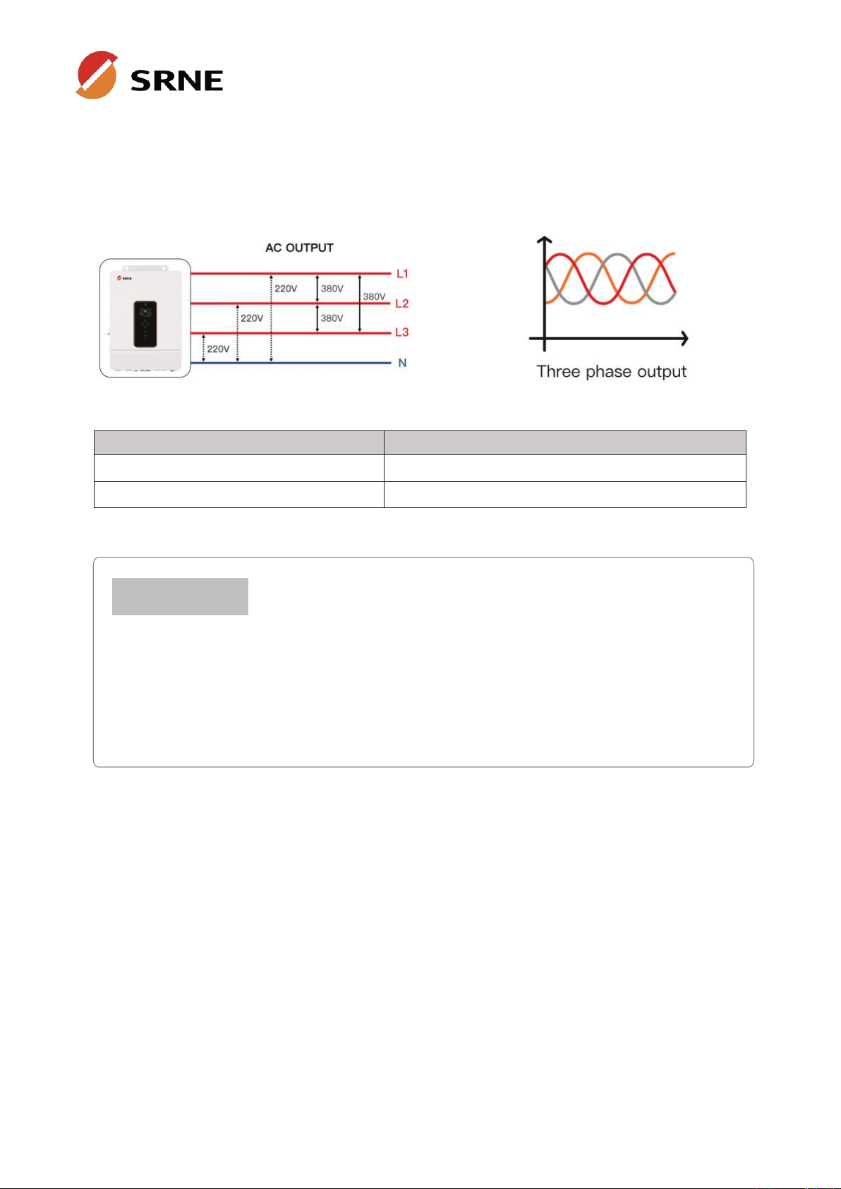
The user can change the output phase mode and output voltage through the setup menu,
please read chapter 5.2 for details.
The output voltage corresponds to item [38] of the parameter setting, and the output
phase voltage can be set within the range of 200V to 240V.
4. Connection
4.1 Three-phase mode
Items
Description
Applicable models
ASF series SH3 model
AC output phase voltage (L-N)
200~240Vac, 230Vac default
○
!
NOTICE

8
File version: V1.0
9
File version: V1.0
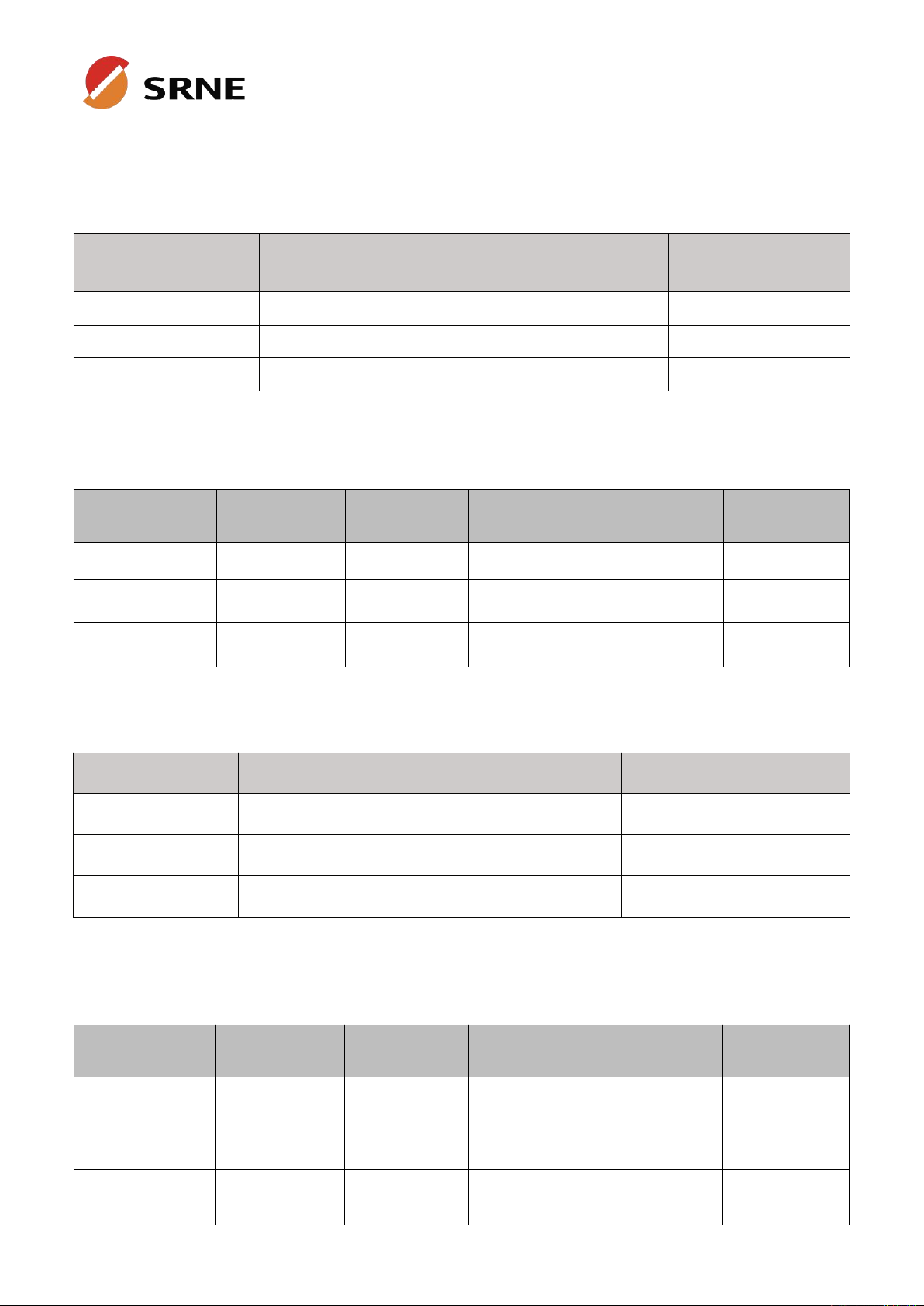
4.2 Cable & circuit breaker requirement
• PV input
Models
Cable Diameter
Max. PV Input
Current
Circuit
Breaker Spec
ASF4880SH3
5mm²/ 10 AWG
22A
2P-25A
ASF48100SH3
5mm²/ 10 AWG
22A
2P-25A
ASF48120SH3
5mm²/ 10 AWG
22A
2P-25A
• AC input
• Battery
• AC output
Models
Output Mode
Max. Current
Cable Diameter
Circuit
Breaker Spec
ASF4880SH3
Three-phase
25.5A
6mm²/8 AWG(L1/L2/L3/N)
4P-40A
ASF48100SH3
Three-phase
31.9A
7mm²/8 AWG(L1/L2/L3/N)
4P-50A
ASF48120SH3
Three-phase
38.2A
9mm²/6 AWG(L1/L2/L3/N)
4P-63A
Models
Cable Diameter
Max. Current
Circuit Breaker Spec
ASF4880SH3
34mm²/ 2 AWG
180A
2P-200A
ASF48100SH3
42mm²/ 1 AWG
220A
2P-250A
ASF48120SH3
50mm²/ 1 AWG
260A
2P-300A
Models
Output Mode
Max. Current
Cable Diameter
Circuit
Breaker Spec
ASF4880SH3
Three-phase
12.8A
3mm²/12 AWG(L1/L2/L3/N)
4P-20A
ASF48100SH3
Three-phase
16A
4mm²/10 AWG(L1/L2/L3/N)
4P-25A
ASF48120SH3
Three-phase
19.2A
5mm²/10 AWG(L1/L2/L3/N)
4P-32A
10
File version: V1.0
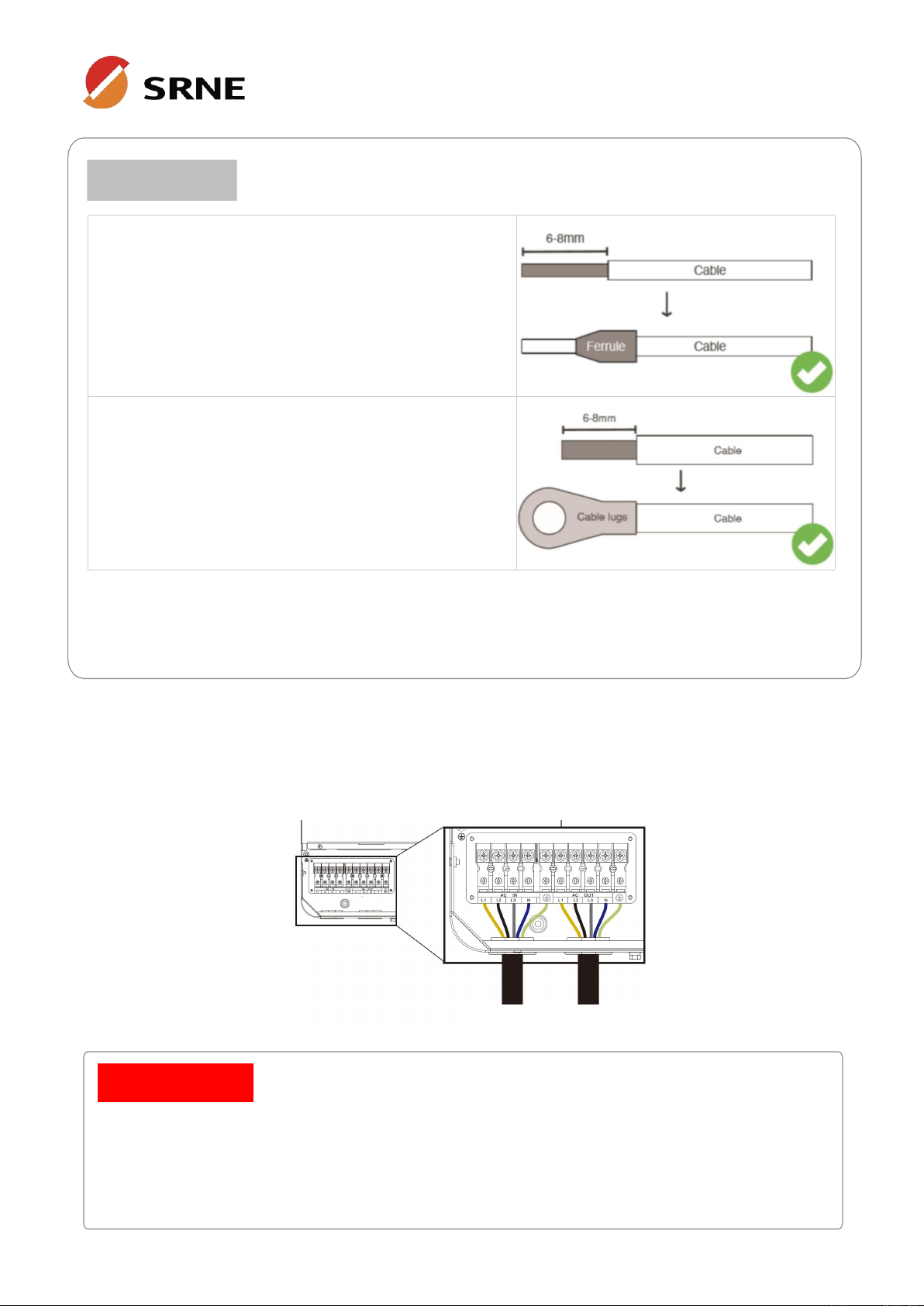
•PV input, AC input, AC output
1. Use a stripper to remove the 6~8mm insulation of the
cable.
2.
Fixing a ferrule at the end of the cable (ferrule needs to
be prepared by the user).
•Battery
1. Use a stripper to remove the 6~8mm insulation of the
cable.
2. Fixing cable lugs that supply with the box at the end
of the cable.
The wire diameter is for reference only. If the distance between the PV array and the inverter or
between the inverter and the battery is long, using a thicker wire will reduce the voltage drop and
improve the performance of the system.
4.3 AC input & output connection
Connect the live, neutral and ground cables in the position and order of the cables as shown in the
diagram below.
○
!
NOTICE
•Before connecting the AC input and output, the circuit breaker must be disconnected to
avoid the risk of electric shock and must not be operated with electricity.
•Please check that the cable used is sufficient for the requirements, too thin, poor quality
cables are a serious safety hazard.
△
!
DANGER
AC input
AC output

11
File version: V1.0
4.4 Battery connection
Connect the positive and negative cable of the battery according to the diagram below.
4.5 PV connection
Connect the positive and negative wires of the two strings of PV according to the diagram below.
•Before connecting the battery, the circuit breaker must be disconnected to avoid the
risk of electric shock and must not be operated with electricity.
•Please ensure that the positive and negative terminals of the batteries are correctly
connected and not reversed, otherwise the inverter may be damaged.
•Please check that the cable used is sufficient for the requirements, too thin, poor
quality cables are a serious safety hazard.
△
!
DANGER
•Before connecting the PV, the circuit breaker must be disconnected to avoid the risk of
electric shock and must not be operated with electricity.
•Make sure that the open-circuit voltage of the PV modules connected in series does
not exceed the maximum open-circuit voltage of the inverter (the value is 800V),
otherwise the inverter may be damaged.
△
!
DANGER

12
File version: V1.0
•Grounding wire shall be not less than 4 mm² in diameter and as close as possible to the
earthing point.
4.6 Dry contact connection
Use a small screwdriver to push back the direction indicated by the arrow, and then insert the
communication cable into the dry junction port. (Communication cable cross section 0.2~1.5mm2)
4.7 Grounding connection
Make sure that the earth terminal is securely connected to the grounding busbar.
4.8 Final assembly
After ensuring that the wiring is reliable and the wire sequence is correct, restore the terminal protection
cover to its original position.
4.9 Start-up the inverter
•Step 1:Close the circuit breaker of the battery.
•Step 2:Press the ON/OFF switch on the bottom of the inverter, the screen and the indicator
light come on to indicate that the inverter is activated.
•Step 3:Sequential close of the circuit breakers for PV, AC input and AC output.
•Step 4:Start the loads one by one in order of power from small to large.
○
!
NOTICE
13
File version: V1.0
5. Operation
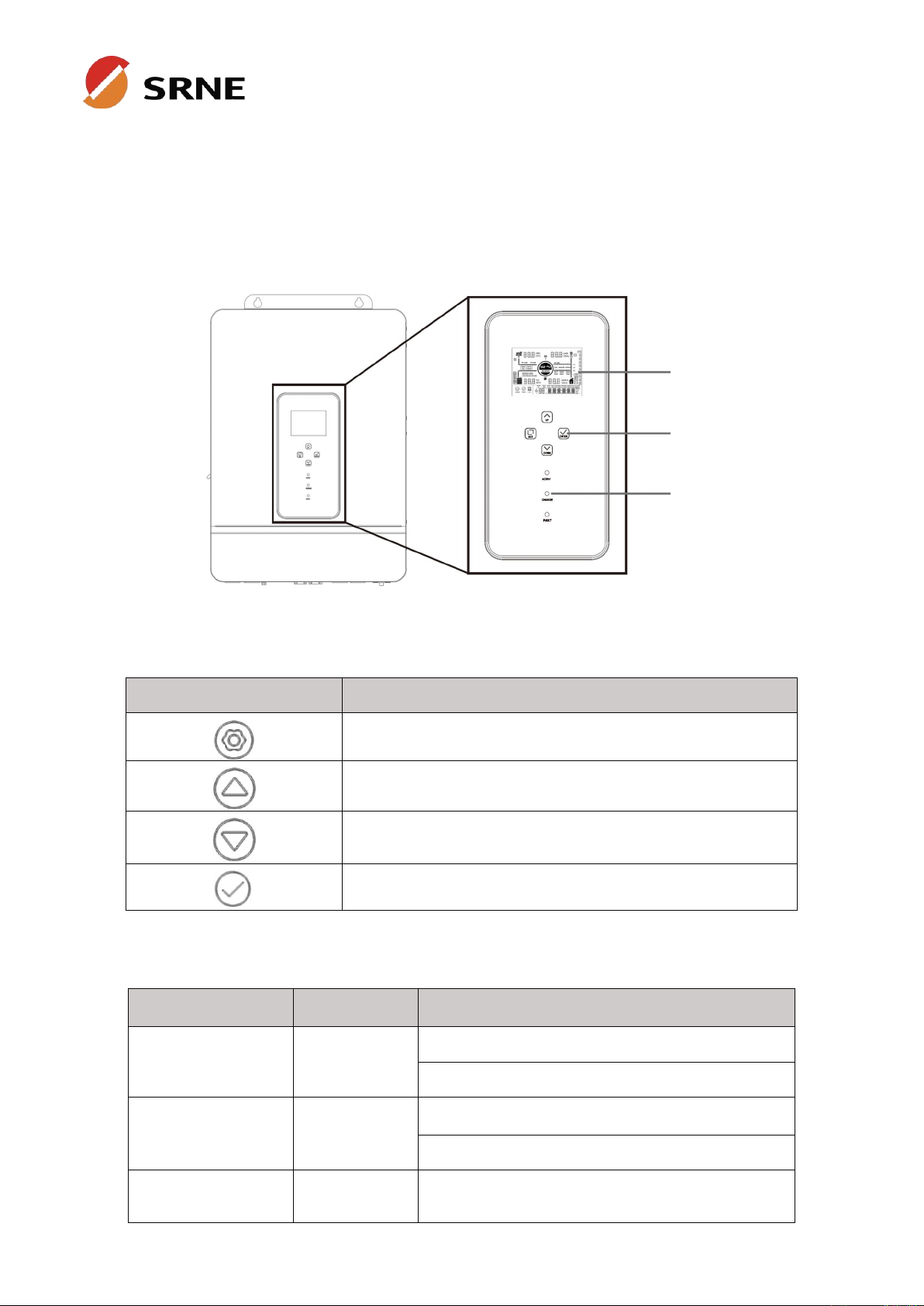
5.1 Operation and display panel
The operation and display panel below includes 1 LCD screen, 3 indicators, 4 touchable keys.
• Touchable keys
Touchable keys
Description
To enter/exit the setting menu
To next selection
To last selection
To confirm/enter the selection in setting menu
•
LED Indicators
LED Indicators
Color
Description
AC/INV
Green
Always on: utility bypass output
Flash: inverter output
CHARGE
Yellow
Always on: charging complete
Flash: charging
FAULT
Red
Flash: fault occur
LCD screen
Touchable keys
LED indicators

14
File version: V1.0
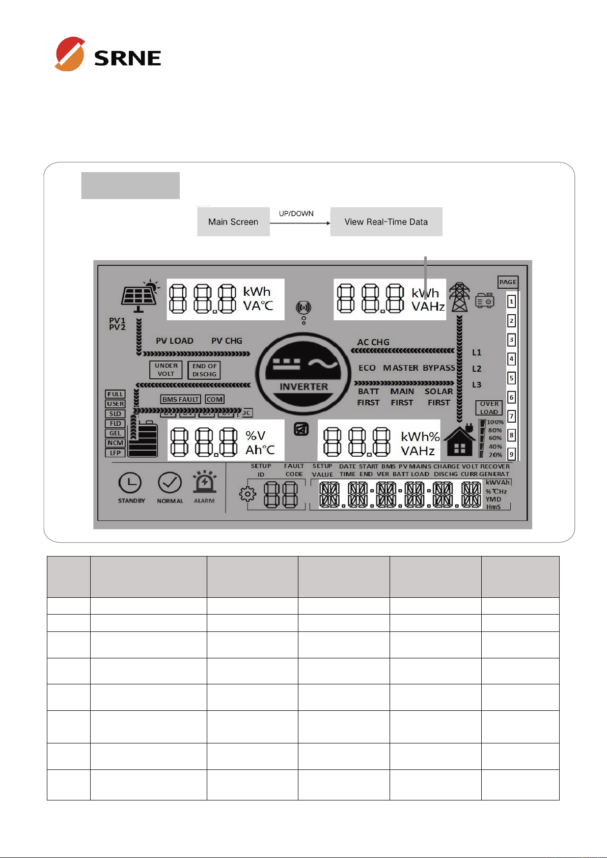
• Display panel
Icon
Description
Icon
Description
Indicates the PV panel
Indicates the utility grid
Indicates the battery
Indicates the generator
Indicates the inverter is
working
Indicates the home load
Indicates the inverter is
communicating with data
collector
Indicates the buzzer
muted
Indicates the direction of energy flow
Indicates the inverter is
standby
Indicates the inverter is
working normally
Indicates error occur
Indicates setting

15
File version: V1.0
Icon
Description
Icon
Description
Indicates load power
80%~100%
Indicates battery SOC
80%~100%
Indicates load power
60%~79%
Indicates battery SOC
60%~79%
Indicates load power
40%~59%
Indicates battery SOC
40%~59%
Indicates load power
20%~39%
Indicates battery SOC
20%~39%
Indicates load power 5%~19%
Indicates battery SOC 5%~19%
Indicates battery under-voltage
Indicates battery discharge
stops
Indicates over-load
Indicates BMS fault
Indicates system
communication error
Indicates system under-voltage
Indicates system over-voltage
Indicates system under
temperature
Indicates system
overtemperature
Indicates system over-current
Indicates battery is full
Indicates user defined battery
Indicates sealed lead-acid
battery
Indicates flooded lead-acid
battery
Indicates gel lead-acid battery
Indicates ternary li-ion battery
Indicates LFP li-ion battery
ECO
Indicates energy-saving mode
PV LOAD
Indicates PV energy is carrying
the load
PV CHG
Indicates PV energy is charging
the battery
AC CHG
Indicates AC IN energy is
charging the battery
MAIN
FIRST
Indicates the inverter output
mode is mains power first
BYPASS
Indicates the inverter output
mode is bypass
SOLAR
FIRST
Indicates the inverter output
mode is solar first
BATT
FIRST
Indicates the inverter output
mode is battery first
16
File version: V1.0
real-time data
•View real-time data
In the main screen,press the UP / DOWN keys to view the real-time data of the inverter during
operation.
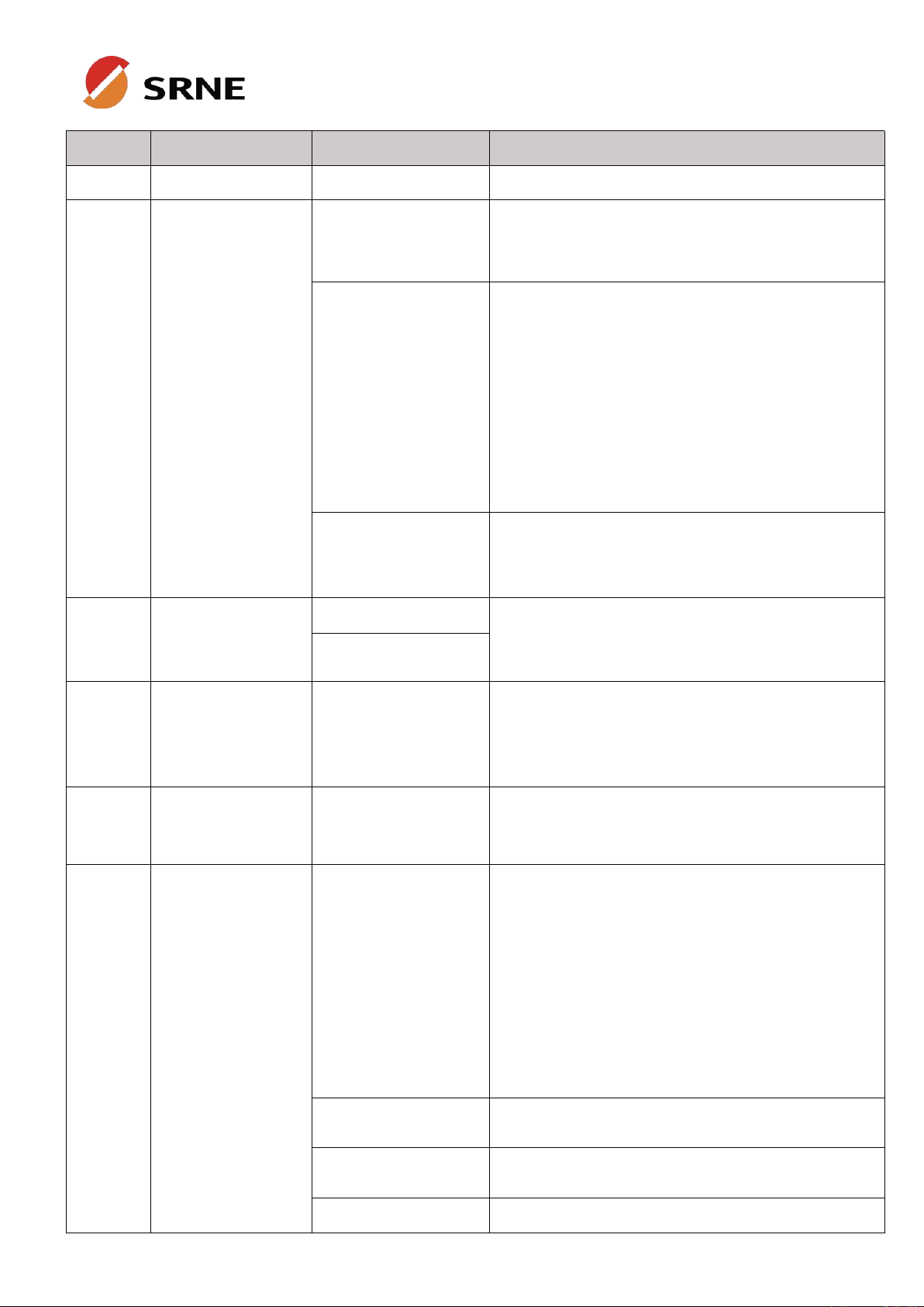
Page
PV side
BAT side
AC IN side
LOAD side
General
1
PV input voltage
Batt Voltage
AC IN voltage
phase voltage
Current Time
2
PV input current
Batt Current
AC IN current
phase current
Current Date
3
PV input power
Batt Voltage
Total AC IN power
phase active
power
PV Total kWh
4
PV today kWh
Batt Current
Today AC
charging kWh
phase apparent
power
Load Total kWh
5
PV side heat sink
temperature
INV Heat Sink
Temperature
AC frequency
AC output
frequency
RS485 Address
6
Rated open-circuit
voltage
Batt Rated
Voltage
Busbar voltage
Rated output
power
Soft Version
7
Max. PV charging
current
Max.Batt charging
current
Max. AC charging
current
Total AC output
active power
/
8
/
Total AC output
apparent power
/
○
!
NOTICE

17
File version: V1.0
5.2 Setting
18
File version: V1.0
ID
Parameter Meaning
Options
Description
00
Exit
ESC
Exit the setup menu.
01
AC output source
priority
UTI default
Utility Priority. Utility power is given priority to the
loads, the battery inverts to provide power to the
load only when utility power is unavailable.
SBU
Prioritises the use of PV to power the load and
switches back to the mains to power the load only
when the battery voltage is lower than the set
value in parameter item [4] (when connected to
the BMS, according to item [61]). When the battery
voltage is higher than the value set in parameter
[5] (when connected to the BMS, according to item
[62]), it switches back to the PV from the mains to
supply the load.
SOL
PV priority. Switching to mains to power the load
when PV is not effective or when the battery is
below the setting of parameter item [4].
02
AC output
frequency
50.0 default
In mains mode the AC output frequency will adapt
to the mains frequency, otherwise the output will
follow the preset values.
60.0
04
Voltage point of
battery switch to
utility
43.6 default
When parameter [01]= SBU/SOL, output source
will switch to utility from battery when the battery
voltage below the preset value. Setting
range:40~52V.
05
Voltage point of
utility switch to
battery
56.8 default
When parameter [01]=SBU/SOL, output source will
switch to battery from utility when the battery
voltage above the preset value. Range:48~60V.
06
Battery charging
mode
SNU default
Solar and utility charging the battery at the same
time, solar at the first priority, utility power as a
supplement when solar power is not sufficient.
When solar power is sufficient, the utility stops
charging.
Note: The PV and mains can only be charged at
the same time when the mains bypass output is
loaded. When the inverter is operating, only PV
charging can be initiated, not utility charging.
CUB
Utility is the first priority in charging, PV charging
the battery only when utility is not available.
CSO
PV is the first priority in charging, utility charging
the battery only when solar power is not sufficient.
OSO
PV charging only, no utility charging.
This manual suits for next models
2
Table of contents
Other Srne Inverter manuals

Srne
Srne HF4830S80-145 User manual

Srne
Srne HES4880S200-H User manual

Srne
Srne ASF4880U180-H User manual

Srne
Srne HFP4850S80-145 User manual

Srne
Srne BP Series User manual

Srne
Srne HES4840S100-H User manual

Srne
Srne HT4825U80 -145 User manual

Srne
Srne HF4825U80-145 User manual

Srne
Srne SR-HF2420S40-75 User manual

Srne
Srne HF2420S40-75 User manual

Srne
Srne HES4855S100-H User manual

Srne
Srne HT4830S80-145 User manual

Srne
Srne HFP4850S80-H User manual

Srne
Srne HF2420U60-100 User manual

Srne
Srne HESP4860S100-H User manual

Srne
Srne ASF4880S180-H User manual

Srne
Srne IU Series User manual

Srne
Srne HYP4850S100-H User manual

Srne
Srne HF2430S80-H User manual

Srne
Srne MC Series User manual


