3.4.2 Connecting the BMS power supply cable
The hybrid inverter is installed correctly and reliably.
Ground cables are connected securely.
All switches are in the OFF position.
All cables are connected correctly and securely.
The cover of the AC junction box is secured.
All the unused connectors are sealed.
The right panel is closed and secured.
Put away the unused accessories.
The installation position is clean and tidy.
Before power-on, please make sure all components remain within their permitted operating ranges. Otherwise it will cause damage to the
hybrid inverter.
Perform the following steps to power on the system:
1. Ensure that there is no voltage on the PV side, then turn on the DC switches.
2. Turn on the breaker between the grid and the inverter.
3. Turn on the breaker between the battery and the inverter, then turn on the switch on the battery.
4. The system will be powered on automatically when all the requirements are met.
To shut down the system, you need to send a shutdown command on the APP or website. Wait until the system is completely powered off,
then turn off the switches in reverse order.
PV+
PV-
3.3.2 Connecting the DC input cables
1.Before installing the PV terminals, please
confirm that the PV input voltage and current
do not exceed the MPPT limits.
2.When installing the PV terminals, identify
the positive and negative terminals and
connect them to the inverter respectively
following the color convention.
3.A "click" sound will be heard when the
terminal is connected. Please gently pull the
PV cable back to make sure it is securely
connected.
12
GR-UM-318-A-01
Download
Manual
Growatt New Energy
Shenzhen Growatt New Energy Co., Ltd
4-13/F, Building A, Sino-German (Europe) Industrial Park,
Hangcheng Ave, Bao'an District, Shenzhen, China
2
Follow the installation
steps:
1. Remove the waterproof
cover from the USB port.
2. Plug in the datalogger.
3. Secure the datalogger.
The inverter side
Parallel communication port
3.5.6 Communication module installation
A
B
C
D
E
F
G
H
I
USB
The inverter side
USB
Notes:
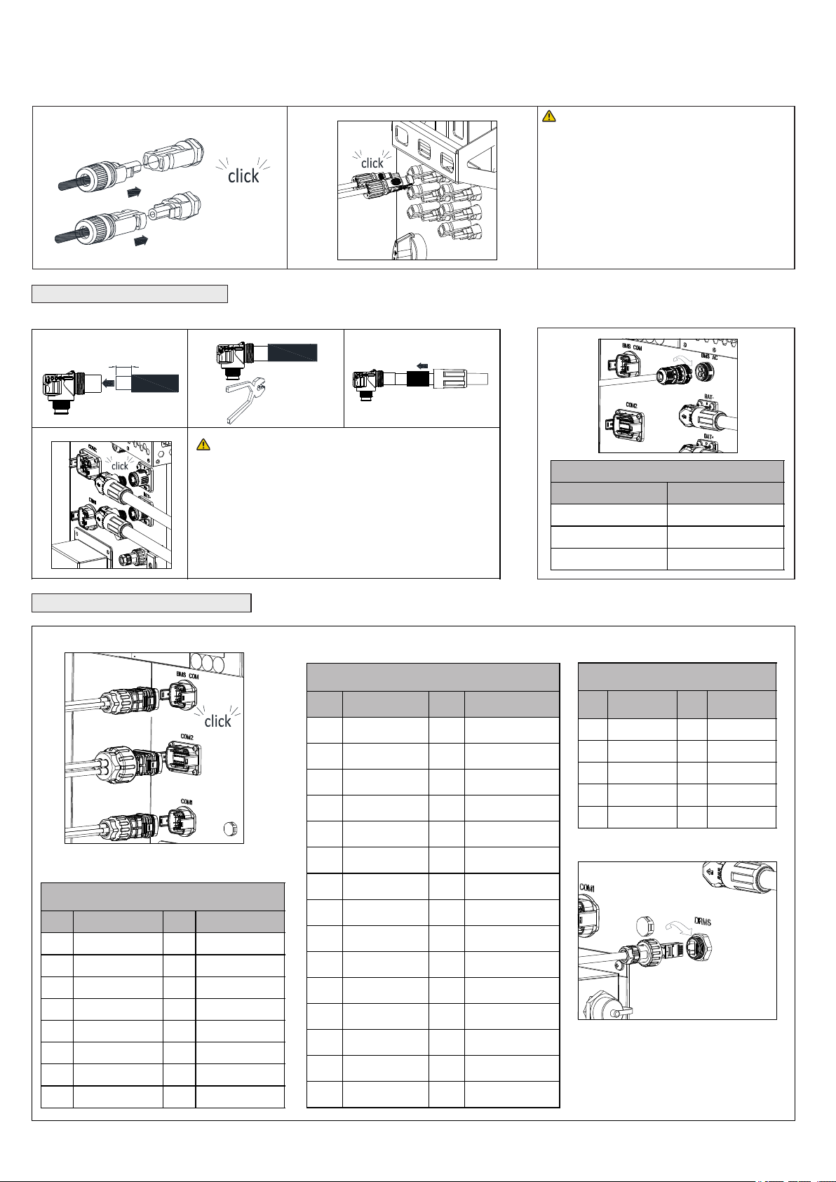
3.4 Connection on the battery side
18-20 mm
1
3.4.1 Connecting the battery power cable
Monitor communication port
Notes:
1. Before installing the battery terminals, please
ensure that the battery input voltage and current are
within the acceptable range.
2. When installing battery terminals, identify the
positive and negative terminals and connect them to
the inverter according to the color convention.
3. When connecting the terminals, ensure that you hear
a "click" sound. Please gently pull back the battery
cables to ensure a secure connection.
BMS power supply port description
2 3
4
3.5 Installing the communication cable
BMS communication port
4.
Post-installation check
3.5.6 Communication module installation
5.
Powering on/off the inverter
Note:
3.5.6 Communication module installation
6.
Description of the display panel
Battery connection indicator
31
BMS Communication port
description(BMS-COM)
Parallel communication port
description(COM2)
Follow the installation steps:
1. Remove the waterproof cover from
the network communication port.
2. Insert a network cable into the port
and tighten the protective cover.
Monitor communication port
description(COM1)
Network communication port
3.5.6 Communication module installation
7.
Service and contact
3.5.6 Installing the datalogger
+86 755 2747 1942
www.ginverter.com
T
E service@ginverter.com
W