Solar Hybrid Inverter V1.0 4
1. General information
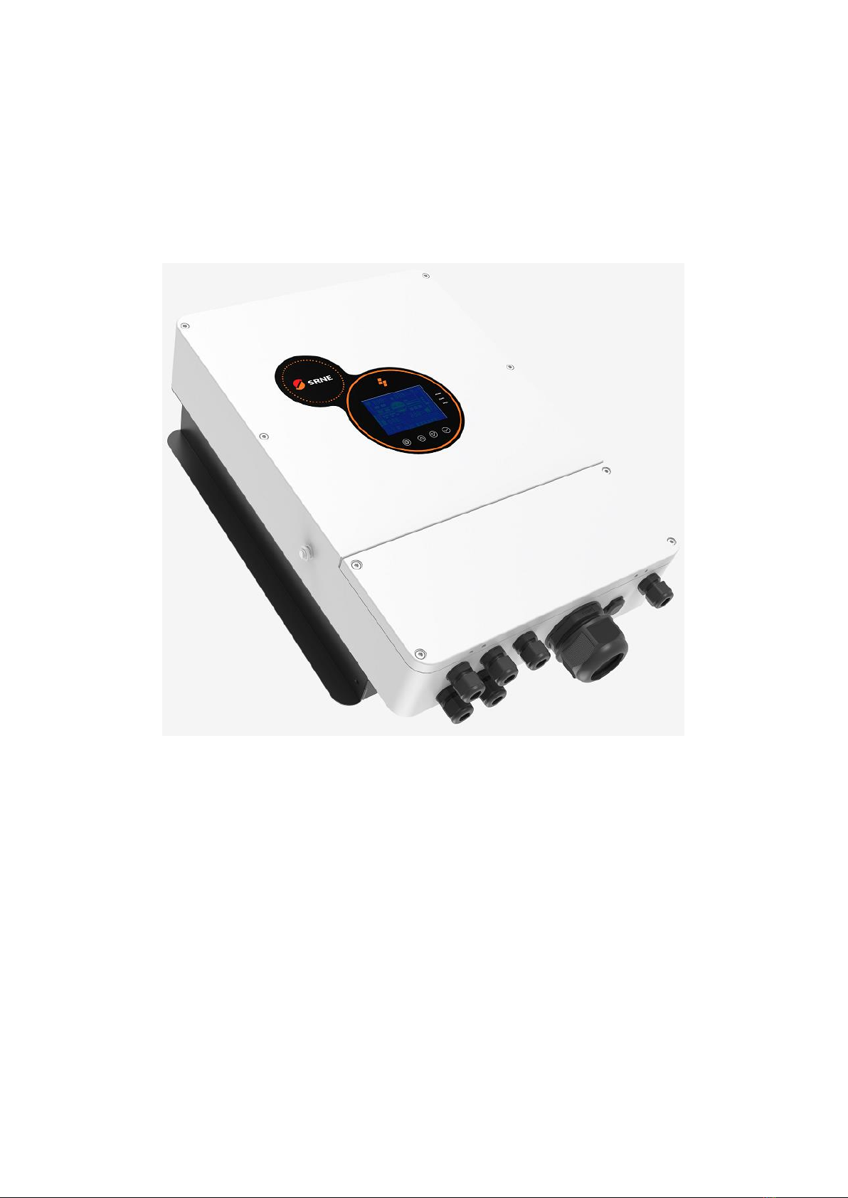
1.1 Product overview and features
HES series is a new type of solar hybrid inverter, integrating solar energy storage and mains charging and AC
sine-wave output. It is controlled by DSP and has the features of high response speed, high reliability and high
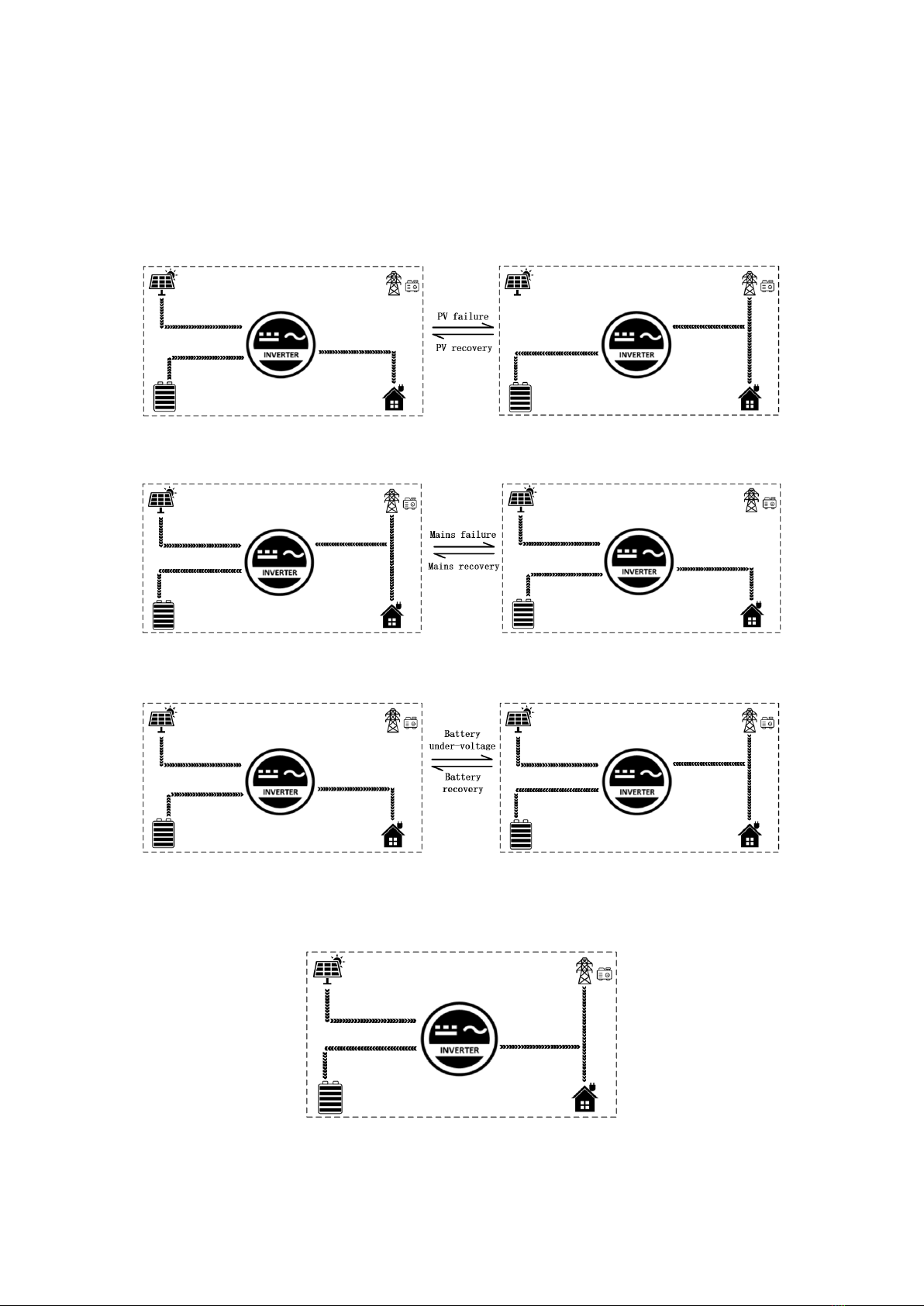
industrial standard through state-of-art control algorithm. It has four charging modes: solar only, mains priority, solar
power priority and solar hybrid; two output modes of inverter and Mains Power can be selected to meet different
application requirements.
The solar charging module adopts the latest optimized MPPT technology, which can quickly track the MPP of PV
array in any environment, obtain the maximum energy of solar panel in real time, and has a wide MPPT voltage range.
AC-DC charging module adopts state-of-art control algorithm for full digital double closed-loop control of
voltage and current, which has high control precision and small size. Wide AC voltage input range, complete I/O
protection functions, stable and reliable realization of battery charging and protection.
The DC-AC inverter module is based on all-digital intelligent design, adopting state-of-art SPWM technology,
outputting pure sine wave, converting DC to AC, and thus suitable for AC loads such as household appliances, electric
tools, industrial equipment, electronic audio and video, etc. The product adopts sectional LCD display design, which
displays the running data and running status of the system in real time. The comprehensive electronic protection
function can ensure that the entire system be safer and more stable.
Characteristics:
1. Sectional charging and discharging function available, able to enable and disable AC charging function based on
the charging section time be set, switch power supply mode between inverter and AC bypass based on the
discharge section time be set.
2. Anti-counter-current grid-connected function (PV and mains hybrid power supply).
3. It has insulation impedance and leakage current detection function.
4. Support for use under battery-free conditions.
5. It has double activation function of lithium battery, which can be triggered by connecting any mains/PV power.
6. With the function of ECO mode and reducing no-load loss.
7. There are 4 charging modes available: solar only, Mains Power first, solar first and hybrid charging.
8. It has two output modes: Mains Power bypass and inverter output, and has the function of uninterrupted power
supply.
9. It has multiple protection functions for 360° omni-directional protection.
10. Support lead-acid battery and lithium battery access.
11. The ON/OFF switch controls the inverter AC output.
12. PV Grid-connected power generation mode can be set.
13. Adopt full digital voltage and current double closed-loop control, state-of-art SPWM technology and output
pure sine wave.
14. Advanced MPPT technology, the efficiency is as high as 99.9%.
15. LCD screen design, 3 LED indicator lights, dynamic display system data and running status.
16. Adopt intelligent adjustable speed fan to dissipate heat efficiently and prolong the service life of the system.
17. Complete short circuit protection, over-voltage and under-voltage protection, overload protection and backfeed
protection available.