Zeus Appollo Z10I1K User manual

User Manual V1.1
User Manual
-Installation
-Operation
Z10I1K
Z10I1K5
Z10I2K
Z10I2K5
Z10I3K
Zeus Appollo Solar


Contents
1. Notes on this manual .........................................................................................................................................................2
1.1 Scope of Validation......................................................................................................................................................2
1.2 Symbols Used .............................................................................................................................................................2
1.3 Target Group ...............................................................................................................................................................3
2. Preparation ........................................................................................................................................................................4
2.1 Safety Instructions .......................................................................................................................................................4
2.2 Explanations of Symbols on Inverter ...........................................................................................................................6
3. Product Information............................................................................................................................................................7
3.1 Overview......................................................................................................................................................................7
3.2 Major Characteristics...................................................................................................................................................8
3.3 Datasheet ....................................................................................................................................................................9
4. Packing checklist .............................................................................................................................................................13
4.1 Assembly parts ..........................................................................................................................................................13
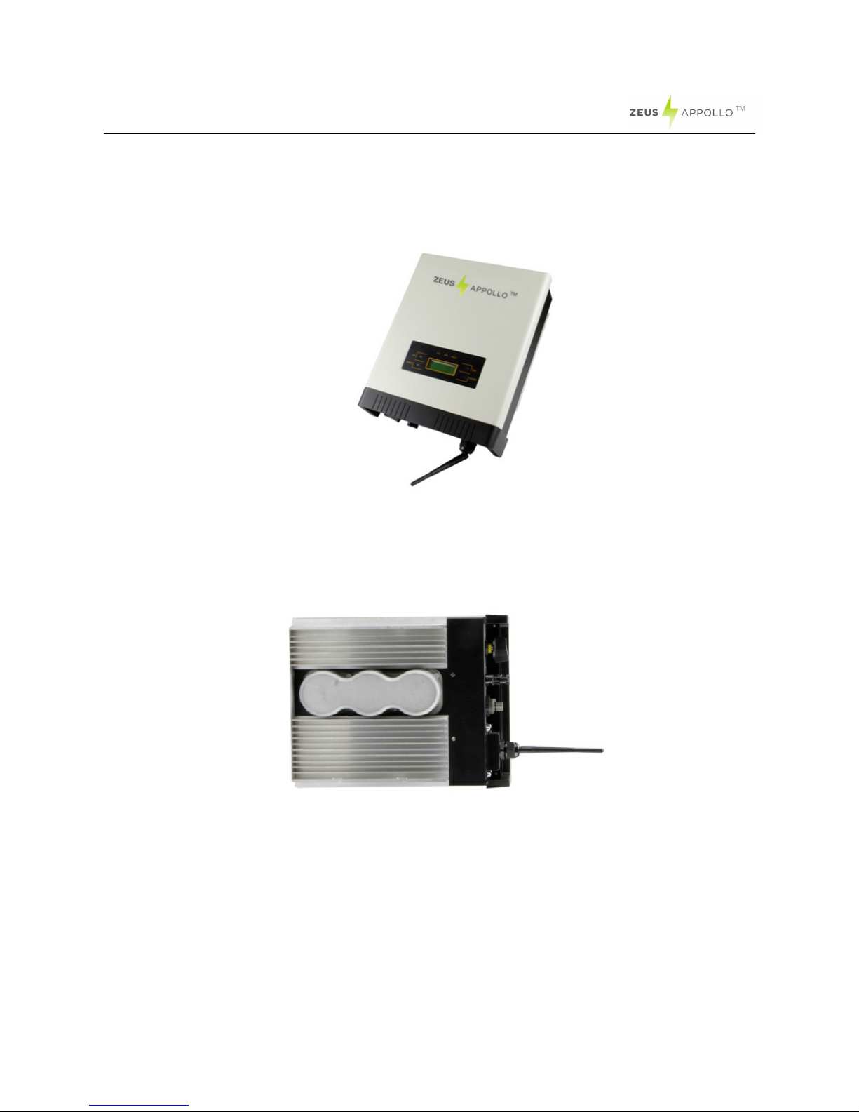
4.2 Product Appearance..................................................................................................................................................14
4.3 Product Identification .................................................................................................................................................15
4.4 Further Information .................................................................................................................................................... 15
5. Installation........................................................................................................................................................................16
5.1 Safety ........................................................................................................................................................................16
5.2 Mounting Instructions.................................................................................................................................................17
5.3 Safety Clearance .......................................................................................................................................................18
5.4 Mounting Procedure ..................................................................................................................................................19
5.5 Safety lock ................................................................................................................................................................. 22
6. Electrical Connection .....................................................................................................................................................233
6.1 Safety ......................................................................................................................................................................233
6.2 AC Side Connection ................................................................................................................................................233
6.3 DC Side Connection .................................................................................................................................................. 26
6.4 Communication and Monitoring Device .....................................................................................................................32
7. Display and Operation .....................................................................................................................................................32
7.1 LCD Panel .................................................................................................................................................................32
7.2 Commissioning ........................................................................................................................................................344
7.3 Operation.................................................................................................................................................................344
7.4 State Information .....................................................................................................................................................466
8. Troubleshooting ............................................................................................................................................................477
9. Abbreviation .....................................................................................................................................................................49
10. Contact.............................................................................................................................................................................50

2
1. Notes on this manual
1.1 Scope of Validation
The main purpose of this User Manual is to provide instructions and detailed procedures
for installing, operating, maintaining, and troubleshooting the following five types of Z10
series inverters:
•Z10I1K
•Z10I1K5
•Z10I2K
•Z10I2K5
•Z10I3K
Please keep this user manual available at all times in case of emergency.
1.2 Symbols Used
CAUTION
CAUTION indicates a hazardous condition which, if not
avoided, can result in minor or moderate injury.
WARNING
WARNING indicates a hazardous situation which, if not
avoided, can result in death or serious injury or moderate
injury.
DANGER
DANGER indicates a hazardous situation which, if not
avoided, will result in death or serious injury.

3
1.3 Target Group
•Chapter1, 2, 3, 4, 7, 8, 9, 10 and chapter 11 are provided for anyone who is intending
to use a Z10 Series Grid-tied Solar Inverter. Before any further action is taken, the
operators must first read all safety regulations and be aware of the potential danger
when operating high-voltage devices. Operators must also have a complete
understanding of this device’s features and functions.
•Chapter 5 and chapter 6 are only for qualified personnel who are intending to install
or uninstall the Z10 Series Grid-tied Solar Inverter.
NOTICE
Qualified personnel means he/she has a valid license from
the local authority in:
•Installing electrical equipment and PV power systems (up to
1000 V).
•Applying all relevant installation codes.
•Analyzing and reducing the hazards involved in performing
electrical work.
•Selecting and using Personal Protective Equipment (PPE).
WARNING
Do not use this product unless it has been successfully
installed by qualified personnel in accordance with the
instructions in Chapter 5. “Installation”
NOTICE
NOTICE indicates a situation that can result in property
damage, if not avoided.

4
2. Preparation
2.1 Safety Instructions
WARNING
The installation, recycling and disposal of the inverters must
be performed by qualified personnel who must comply with
national and local standards and regulations. Please contact
your dealer to obtain details about an authorized repair
facility if the inverter requires maintenance or repair. Any
unauthorized activities including the modification of product
functionality of any kind will affect the extent of the warranty;
such actions may result in Zeus Appollo Solar not accepting
any responsibility for that warranty.
DANGER
DANGER due to electrical shock and high voltage
DO NOT touch the operating component of the inverter, it
might result in burning or death.
TO prevent risk of electric shock during installation and
maintenance, please make sure that all AC and DC
terminals are unplugged.
DO NOT remain close to the equipment while there are
severe weather conditions including storms, lightning etc.

5
CAUTION
The PV inverter will become hot during operation; please
do not touch the heat sink or adjacent surfaces during or
shortly after operation.
Risk of damage due to modifications. Never modify or
manipulate the inverter or other components of the system.
NOTICE
Public utility only
The PV inverter is designed to feed AC power directly into
the public utility power grid; do not connect the AC output of
the device to any private AC equipment.

6
2.2 Explanations of Symbols on Inverter
Symbol Description
Dangerous electrical voltage
This device is directly connected to public grid, consequently all work
on the inverter shall only be carried out by qualified personnel.
DANGER to life due to high electrical voltage!
There might be residual currents present within the inverter because
of large capacitors. Wait
10 MINUTES
before you remove the front lid.
NOTICE, danger!
This device directly connected with electricity generators and the
public grid.
Danger of hot surface
The components inside the inverter will generate heat during
operation,
DO NOT
touch aluminum housing during operation.
An error has occurred
Please go to Part 9 “Trouble Shooting” to remedy the error.
This device SHALL NOT be disposed of in residential waste
Please go to Part 8 “Recycling and Disposal” for proper treatments.
Without Transformer
This inverter does not use a transformer for the isolation function.
Standards Association of Australian
The inverter complies with the requirement of the AS4777.
CE Mark
Equipment with the CE mark fulfils the basic requirements of the
Guideline Governing Low-Voltage and Electromagnetic Compatibility.
No unauthorized perforations or modifications
Any unauthorized perforations or modifications are strictly forbidden, if
any defect or damage (device/person) occurs, Zeus Appollo Solar will
not be held responsible.

7
3. Product Information
3.1 Overview
•
Industrial Layout
•
Excellent Heat Elimination
•
Effective Shield For DC/AC/Communication Connections

8
3.2 Major Characteristics
The Z10 series inverter has the following characteristics which ensures that it delivers
on the promise of “high efficiency, high reliability, and having a high cost effective ratio”
•
An extensive DC input voltage and current range which enables more PV panels to
be connected.
•
A wide MPP voltage range will ensure a high yield under various weather conditions.
•
A high MPP tracking accuracy ensures minimum power losses during conversion.
The following protection methods are integrated into the Z10 series inverter:
•
Internal overvoltage
•
DC insulation monitoring
•
Ground fault protection
•
Grid monitoring
•
Ground fault current monitoring
•
DC current monitoring
•
Integrated DC switch (Optional)

9
3.3 Datasheet
Type Z10I1K Z10I1K5 Z10I2K
Input (DC)
Max. PV Power 1300W 1750W 2300W
Max DC Voltage 500V 500V 500V
Nominal DC Voltage 360V 360V 360V
Operating MPPT Voltage
Range 80-360V 120-450V 120-450V
MPPT Voltage Range at
Nominal Power 150-360V 150-450V 150-450V
Start up DC Voltage 90V 150V 150V
Turn off DC Voltage 80V 120V 120V
Max. DC Current 16A 18A 18A
Max. Short Circuit Current
for each MPPT 20A 20A 20A
Number of MPP trackers 1 1 1
Number of DC Connection
for each MPPT 1 1 1
DC Connection Type MC4 Connector MC4 Connector MC4 Connector
Output (AC)
Max. AC Apparent Power
1100VA 1650VA 2200VA
Nominal AC Power
(cos phi = 1) 1000W 1500W 2000W
Nominal Grid Voltage 220V/230V/240V 220V/230V/240V 220V/230V/240V
Nominal Grid Frequency 50Hz/60Hz 50Hz/60Hz 50Hz/60Hz
Max. AC Current 5.8A 9.0A 12.0A
Grid Voltage Range* 185-276V 185-276V 185-276V
Grid Frequency Range* 45-55Hz/55-65Hz 45-55Hz/55-65Hz 45-55Hz/55-65Hz
Power Factor 0.95 capacitive…0.95
inductive
0.95 capacitive…0.95
inductive
0.9 capacitive…0.9
inductive
Total Harmonic Distortion
(THD) <2% <2% <2%
Feed in Starting Power 30W 30W 30W
Night time Power
Consumption <1W <1W <1W
Standby Consumption 6W 6W 6W
AC Connection Type Plug-in connector Plug-in connector Plug-in connector
Efficiency
Max. Efficiency (at
360Vdc) 97.7% 97.7% 97.7%
Euro Efficiency (at
360Vdc) 96.7% 96.8% 96.9%
MPPT Efficiency 99.9% 99.9% 99.9%

10
Type
Z10I1K
Z10I1K5
Z10I2K
Safety and Protection
DC Insulation Monitoring Yes
DC Switch Optional
Residual Current
Monitoring Unit (RCMU) Integrated
Grid Monitoring with Anti-
islanding Yes
Protection Class I (According to IEC 62103)
Overvoltage Category PV II / Mains III (According to IEC 62109-1)
Reference Standard
Safety Standard EN 62109, AS/NZS 3100
EMC Standard EN 61000-6-1, EN 61000-6-3, EN 61000-6-2, EN 61000-6-4, EN61000-3-2,
EN61000-3-3, EN61000-3-11, EN61000-3-12
Grid Standard AS4777
Physical Structure
Dimensions (WxHxD) 343x281x130mm
Weight 11kg
Environmental Protection
Rating IP 65 (According to IEC 60529)
Cooling Concept Natural convection
Mounting Information Wall bracket
General Data
Operating Temperature
Range -20°C to +60°C(derating above 45)
Relative Humidity 0% to 98%, no condensation
Max. Altitude (above sea
level) 2000m
Noise Level < 40dB
Isolation Type Transformerless
Display 3 LED, Backlight, 4 x 20 Character LCD
Data Communication
Interfaces RS485(Wi-Fi, GPRS integrated)
Computer Communication
USB
Standard Warranty 5 Years (10 years optional)
*The AC voltage and frequency range may vary depending on the specific country grid

11
Type Z10I2K5 Z10I3K
Input (DC)
Max. PV Power 2800W 3250W
Max DC Voltage 500V 500V
Nominal DC Voltage 360V 360V
Operating MPPT Voltage Range 120-450V 120-450V
MPPT Voltage Range at Nominal
Power 150-450V 150-450V
Start up DC Voltage 150V 150V
Turn off DC Voltage 120V 120V
Max. DC Current 18A 18A
Max. Short Circuit Current for each
MPPT
20A 20A
Number of MPP trackers 1 1
Number of DC Connection for each
MPPT 1 1
DC Connection Type MC4 Connector MC4 Connector
Output (AC)
Max. AC Apparent Power 2750VA 3000VA
Nominal AC Power(cos phi = 1) 2500W 3000W
Nominal Grid Voltage 220V/230V/240V 220V/230V/240V
Nominal Grid Frequency 50Hz/60Hz 50Hz/60Hz
Max. AC Current 12.5A 14.0A
Grid Voltage Range* 185-276V 185-276V
Grid Frequency Range* 45-55Hz/55-65Hz 45-55Hz/55-65Hz
Power Factor 0.9 capacitive…0.9 inductive 0.9 capacitive…0.9 inductive
Total Harmonic Distortion (THD) <2% <2%
Feed in Starting Power 30W 30W
Night time Power Consumption <1W <1W
Standby Consumption 6W 6W
AC Connection Type Plug-in connector Plug-in connector
Efficiency
Max. Efficiency (at 360Vdc) 97.7% 97.7%
Euro Efficiency (at 360Vdc) 96.9% 97.0%
MPPT Efficiency 99.9% 99.9%

12
Type Z10I2K5 Z10I3K
Safety and Protection
DC Insulation Monitoring Yes
DC Switch Optional
Residual Current Monitoring Unit
(RCMU) Integrated
Grid Monitoring with Anti-islanding Yes
Protection Class I (According to IEC 62103)
Overvoltage Category PV II / Mains III (According to IEC 62109-1)
Reference Standard
Safety Standard EN 62109, AS/NZS 3100
EMC Standard
EN 61000-6-1, EN 61000-6-3, EN 61000-6-2, EN 61000-6-4, EN61000-3-2,
EN61000-3-3,
EN61000-3-11, EN61000-3-12
Grid Standard AS4777
Physical Structure
Dimensions (WxHxD) 343x281x150mm
Weight 9.9kg
Environmental Protection Rating IP 65 (According to IEC 60529)
Cooling Concept Natural convection
Mounting Information Wall bracket
General Data
Operating Temperature Range -20°C to +60°C(derating above 45
℃
)
Relative Humidity 0% to 98%, no condensation
Max. Altitude (above sea level) 2000m
Noise Level < 40dB
Isolation Type Transformerless
Display 3 LED, Backlight, 4 x 20 Character LCD
Data Communication Interfaces RS485(Wi-Fi, GPRS integrated)
Computer Communication USB
Standard Warranty 5 Years (10 years optional)
*The AC voltage and frequency range may vary depending on specific country grid

13
4. Packing checklist
4.1 Assembly parts
After you receive the Z10 series inverter, please check to see if there is any damage to the
carton, and then examine the inverter and accessories for any visible external damage.
Contact your dealer if anything is damaged or missing.
Object Quantity Description
A 1
Z10 series inverter
B 2 pairs
DC connectors
C 1
AC connector
D 1
Wall mounting bracket
E 4
Screws (ST6×50)
F 4
Expansion tubes
G 1
Installation and operating instructions
A B C D
E F G

14
4.2 Product Appearance
•
Front
Object
Description
A Removable front shield
B LED light (3 pcs)
C Function keys for displays and setting(4 pcs)
D Monitoring LCD with backlighting
•
Bottom
A
B
C
D
D
B
C

15
Object
Description
A DC switch (optional)
B Plug connectors for DC input
C Terminal for grid connection (AC output)
D Communication interface(RS485/GPRS/Wi-Fi/USB)
4.3 Product Identification
You can identify the inverter by the side name plate. Information such as the type of
inverter, as well as the inverter specifications are contained on the side name plate. The
name plate is located on the middle part of the right hand side of the inverter housing.
The following figure is an example of the side name plate on the
Z10I2K5
.
4.4 Further Information
If you have any further questions regarding the type of accessories or installation,
please check our website www.zeusappollo.com or contact our service hotline.

16
5. Installation
5.1 Safety
NOTICE
NOTICE An inadequate or incorrect installation may
impact on the published lifespan of the inverter.
Do
NOT
expose to
direct sunlight
to avoid power reduction due
to an increase in the internal temperature of the inverter.
Do
NOT
expose to
rain and snow cover
to enhance inverter life
time.
The installation site
MUST
have good ventilation condition.
DANGER
DANGER to life due to potential fire or electricity shock.
DO NOT
install the inverter near any flammable or explosive
items.
This inverter will be directly connected with a
HIGH VOLTAGE
power generation device; the installation must be performed
by qualified personnel only in compliance with national and
local standards and regulations.

17
5.2 Mounting Instructions
•
Z10 series inverter is designed for both indoor and outdoor installations. Zeus
Appollo Solar recommends installing the inverter in a basement or garage where
there is no direct exposure to sunlight or rain.
•
Do not install in rooms where people live or where the prolonged presence of people
or animals is expected due to the level of noise that the inverter may make during
operation.
•
Please mount the inverter in the direction as illustrated above
.
•
Installing the inverter in the vertical direction is recommended, with a max.15
degrees backwards tilt.
•
For the convenience of checking the LCD display and possible maintenance
activities, please install the inverter at eye level
.
•
Ensure that the wall selected for installation is strong enough for the mounting
screws and can bear the weight of the inverter.
•
Ensure the inverter is properly fixed to the wall
.
•
It is not recommended that the inverter be exposed to strong sunshine. The excess
heat may lead to power reductions
.
•
The ambient temperature of the installation sites should be between -20 °C and
+60 °C (between -4 °F and 140 °F)
.
•
Ensure the installation location is well ventilated. Insufficient ventilation may reduce
the performance of the electronic components inside the inverter and shorten the
lifespan of the inverter
.

18
5.3 Safety Clearance
Observe the following minimum clearances to walls, other devices or objects to
guarantee sufficient heat dissipation and enough space for pulling the electronic solar
switch handle.
Direction Minimum clearance
Above 30 cm
Below 40 cm
Sides 10 cm
This manual suits for next models
4
Table of contents
Other Zeus Appollo Inverter manuals

Zeus Appollo
Zeus Appollo Single Phase Series User manual

Zeus Appollo
Zeus Appollo Z10I3KD User manual

Zeus Appollo
Zeus Appollo Z20I1K User manual

Zeus Appollo
Zeus Appollo Z21 Series User manual

Zeus Appollo
Zeus Appollo Z10I13KDT User manual

Zeus Appollo
Zeus Appollo Z21 Series User manual

Zeus Appollo
Zeus Appollo Z20I4KT User manual
Popular Inverter manuals by other brands

Ingeteam
Ingeteam INGECON SUN STORAGE 1Play Technical guide

MULTIQUIP
MULTIQUIP Whisperwatt DCA25SSIU3 Operation and parts manual

Kaysun
Kaysun KSDF-28 DN4.0 installation manual

Samlexpower
Samlexpower PST-100S-12A owner's manual

gefran
gefran ADL500 Quick start up guide, Specification and installation

Replus
Replus Replus-250 user manual