SRS Light Design DDP 610 PG User manual
Digital dimmer unit
Instruction Manual
Models:
DDP 610 PG, DDP 610 IL
DDP 610 SOX, DDP610 SCH
version 3 /since 6.2011/
TTENTION!
This instruction manual contains important
information about the installation and use of the
equipment. Please read and follow these instructions
carefully.
TTENTION!
Always ensure that the power to the equipment is
disconnected before opening the equipment or
commencing any maintenance work.

SRS Light Design, Rybničná 6/D , 8 1 06 Bratislava, Slovakia, tel:+421244681417,
fax:+421244681419, www.srslight.sk , sales@srslight.sk
2
1. General
IMPORTANT INSTRUCTIONS!
All safety and operating instructions should be read before the equipment is installed
or operated.
IMPORTANT SAFETY INFORMATIONS
The following general safety precautions have to be observed during all phases of
operation, service, and repair of this equipment. Failure to comply with these
precautions or with specific warning in this manual violates safety standards of
design, manufacture, and intended use of this equipment.
Do not operate in an explosive atmosp ere
Do not operate this equipment in the presence of flammable gases or fumes.
Operation of any electrical instrument in such an environment constitutes a definite
safety hazard.
Water, moisture, eat and umidity
Do not operate this equipment near water or in areas with wet floors, also not in high
humidity atmosphere where condensation forms on the equipment. It should never
be placed near or over heat register or other source of heated air and it should not
be installed or operated without proper ventilation.
Power connections
This equipment must be earthed
Wait for at least 10 minutes after the unpacking for adapting of the equipment.
Please double check the signals of the power cable. Cable must be 5 way ( L+N+E)
with the CEE form input socket 2A – 5 pin or hardwired to the installation rack.
Output connection
The output terminals are inside of the dimmer. Live, neutral and earth connections
must be made to all load equipment. Please look at PCB for more info about
connection of outputs/power input.
DMX Input connection
Male and female DMX standard pin and 5pin XLR connectors are based on the back
panel of DDP610. DMX input is opticaly isolated. Analog input (standard 0-10V) are
made thru D-SUB 9 pin connector.
SRS Light Design, Rybničná 6/D , 8 1 06 Bratislava, Slovakia, tel:+421244681417,
fax:+421244681419, www.srslight.sk , sales@srslight.sk
2. Functions and Control
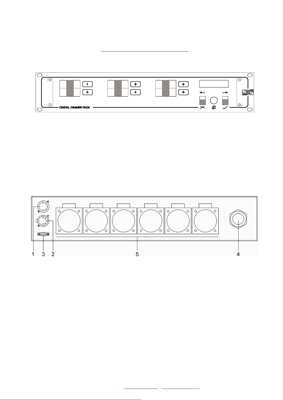
Front panel and controls:
B C
1-6 10A breakers for each output line
ESC button
B Encoder with push button
C ENTER button
Rear panel:
1. DMX input
2. DMX output
. Analogue input – SUB-D 9
4. Power cable input
5. Power outputs – may vary according custommer claims.
Back pannel design may vary according to device upgrade

SRS Light Design, Rybničná 6/D , 8 1 06 Bratislava, Slovakia, tel:+421244681417,
fax:+421244681419, www.srslight.sk , sales@srslight.sk
4
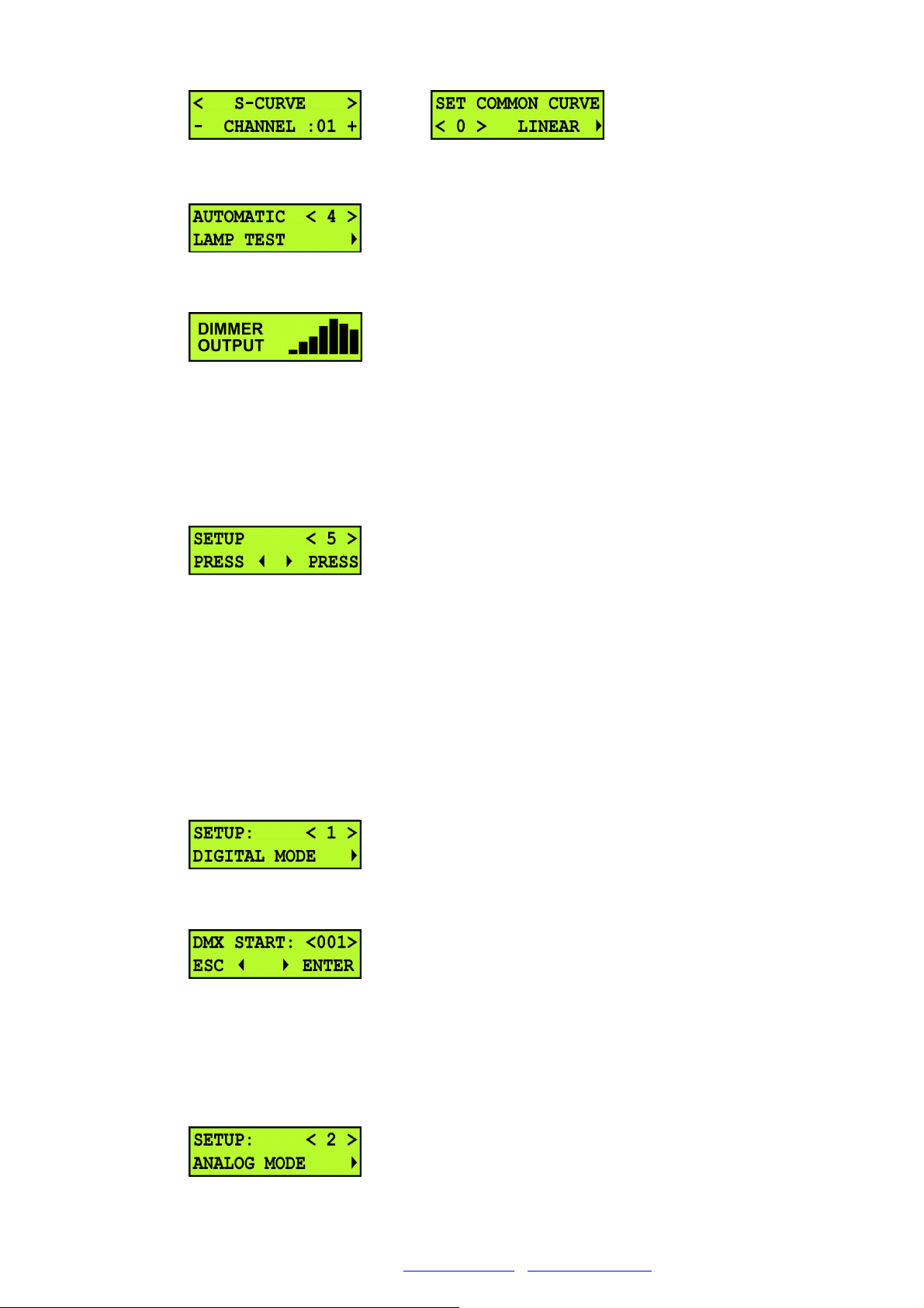
3. Operations
First menu indicate DMX start address, temperature of cooler and main voltage.
Roll to encoder show bargraph output level.
Press encoder for entrance to menu.
Roll to encoder and select function:
•START ADDRESS
•PREHEAT
•CURVES
•AUTOMATIC LAMP TEST
•SETUP
•LOCK
3.1 Set DMX address
Press ENTER button.
Roll ENCODER and set DMX start address - ( 001-512 ).
Press ENTER button.
3.2 Preheat
Left button is preheat for each channel or right button for all channels.
3.3 Dimmer curves
Left button is curves for each channel or right button for all channels.
SRS Light Design, Rybničná 6/D , 8 1 06 Bratislava, Slovakia, tel:+421244681417,
fax:+421244681419, www.srslight.sk , sales@srslight.sk
5
3.4 utomatic lamp test
Press ENTER button.
3.5 Setup
Press two buttons together
Setup has five mode:
•Digital mode
•Analog mode
•Manual mode
•Mix input mode
•Patch mode
3.5.1 Digital mode
Press ENTER button.
Roll ENCODER and set DMX address - (001-512).
Press ENTER button.
DIMMER works only with DMX input.
3.5.2 nalog mode
Press ENTER button.

SRS Light Design, Rybničná 6/D , 8 1 06 Bratislava, Slovakia, tel:+421244681417,
fax:+421244681419, www.srslight.sk , sales@srslight.sk
6
Press ENTER button. DIMMER works only with analog input.
3.5.3 Manual mode
Press ENTER button.
Press ENTER button.
Left and right button select channel and roll encoder and set value.
For escape from this menu PRESS encoder.
DIMMER works without inputs.
3.5.4 Mix mode
Press ENTER button.
Press ENTER button.
Dimmer is switched to HTP mix mode – analog input + DMX input.
3.5.5 Patch mode
Press ENTER button.
SRS Light Design, Rybničná 6/D , 8 1 06 Bratislava, Slovakia, tel:+421244681417,
fax:+421244681419, www.srslight.sk , sales@srslight.sk
7
Right button selects dimm channel. Left button selects controle mode (DMX, analog, manual
mode) for each channel. Encoder maintaince DMX address select number of analog inputs or
value of output manual mode.
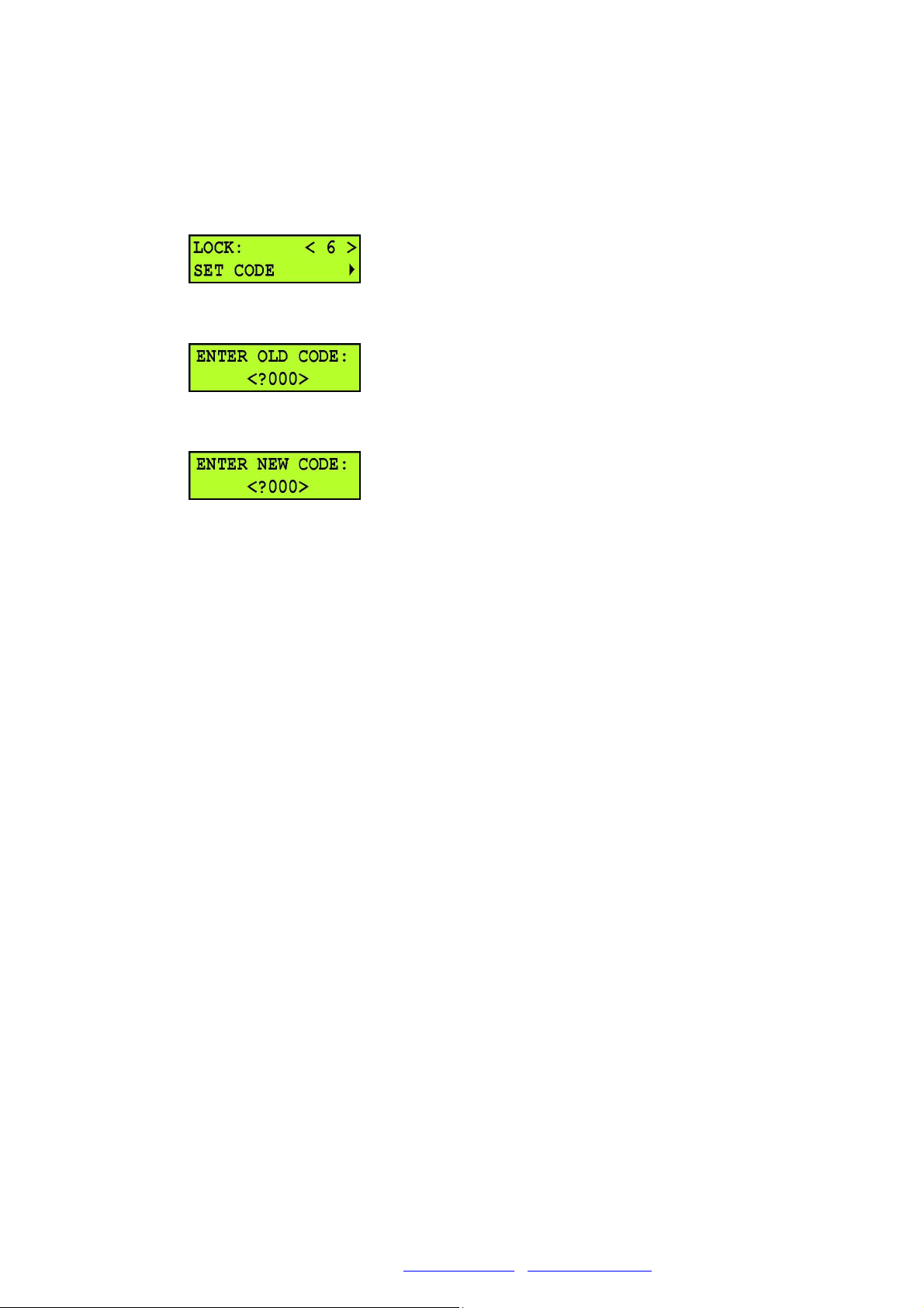
3.6 Lock
Press ENTER button.
Set old code (factory setting is 0000). Press MENU button.
Enter new code and press MENU button. New code is saved. For locking menu press two buttons
together. For unlock press MENU and enter code. Menu is unlocked.

SRS Light Design, Rybničná 6/D , 8 1 06 Bratislava, Slovakia, tel:+421244681417,
fax:+421244681419, www.srslight.sk , sales@srslight.sk
8
4. Menu tree

SRS Light Design, Rybničná 6/D , 8 1 06 Bratislava, Slovakia, tel:+421244681417,
fax:+421244681419, www.srslight.sk , sales@srslight.sk
9
5. Technical data
Dimming capacity:
6 x 2 00 W / 10 A per channel
Interference suppression:
Phase-angle control with triacs and in line precision filters cca 400us
Protection:
Short circuit protection by medium speed automatic circuit breakers
Double thermal protection
Ventilation:
100% duty cycle
Temperature controlled fan
Automatic shutdown at critical temperature
Safety measure:
Showing of all safety features via display
Soft start
Practical attributes:
Controlling of special functions via display, three keys and encoder
Circuit breakers on front panel
Easy change of power output connectors
Display Functions:
Voltage of all phases
Single channels value
Inner temperature
Load status check
DMX signal status

SRS Light Design, Rybničná 6/D , 8 1 06 Bratislava, Slovakia, tel:+421244681417,
fax:+421244681419, www.srslight.sk , sales@srslight.sk
10
Digital menu functions:
Preheat per channel
Dimmer curve per channel
Single channel patch
Variable channel set
DMX processing with fast output response
Hold function for output if DMX data failure
Power Cable:
Recommended Cu rubber cable 5 x 4/6/10 mm
2
Housing:
Steel housing with gray powder coating
482,5 x 88 x 00 mm
Weight:
15 kg
Inputs and Outputs:
Pinout for the XLR connectors:
Pin 1 Ground (not connected with earth)
Pin 2 Data -
Pin Data +
Pin 4,5 Not connected
The DMX output is wired 1:1 to the DMX Input.
Pinout for the SUB-D connector:
Pin 1-6 channel 1-6, analog input (0-10V)
Pin 7 +12V DC output – max 100mA
Pin 8+9 GROUND
Pinout for the SOC PEX connectors:
Pin 1, ,5,7,9,11 Channels 1,2, ,4,5,6
Pin 2,4,6,8,10,12 Neutral
Pin 1 -19 Earth
SRS Light Design, Rybničná 6/D , 8 1 06 Bratislava, Slovakia, tel:+421244681417,
fax:+421244681419, www.srslight.sk , sales@srslight.sk
11
Pinout for the Ilme 16 connectors:
Pin 1-6 Phase 1-6
Pin 9-14 Neutral 1-6
6. Parameters
Processor RISC 8bit
LCD display 2x16 digit with backlight
Risetime 400uS
Filters Iron metal powder core
XLR 5 pin Input: USITT DMX 512 (1990)
XLR pin
Input: Analog 0-10V, max 4 mA 9 pin SUB-D
1 x Socapex 19
1 x Harting 16
6 x Schuko/French/Danish/UK
Output: 6 x 10A
Terminal box (fixed installation)
Main: x 2 0V/50Hz, x 2A Power cable 5 x 6/10 mm
2
Measurement 482,6 x 88 x 00 mm
Weight 15kg

SRS Light Design, Rybničná 6/D , 8 1 06 Bratislava, Slovakia, tel:+421244681417,
fax:+421244681419, www.srslight.sk , sales@srslight.sk
12
7. Contents
1. General....................................................................................................................................... 2
2. Function and control.................................................................................................................
. Operations..................................................................................................................................
.1 Set DMX address............................................................................................................... 4
.2 Preheat............................................................................................................................... 4
. Dimmer curves.................................................................................................................. 4
.4 Automatic lamp test.......................................................................................................... 4
.5 Setup.................................................................................................................................. 5
.5.1 Digital mode............................................................................................................. 5
.5.2 Analogue mode........................................................................................................ 5
.5. Manual mode............................................................................................................ 5
.5.4 Mix input.................................................................................................................. 6
.5.5 Patch......................................................................................................................... 6
.6 Lock.................................................................................................................................. 6
4. Menu tree................................................................................................................................... 7
5. Technical data............................................................................................................................ 8
6. Parameters................................................................................................................................. 10
7. Contents..................................................................................................................................... 12
Bratislava, 1
st
of June 2011
Robert Sloboda
This manual suits for next models
3
Table of contents
Popular Dimmer manuals by other brands

Nexta Tech
Nexta Tech MCU-SEN4 manual

Leviton
Leviton ACM10-1L installation instructions

Jung
Jung 225 NV DE quick start guide

elsner elektronik
elsner elektronik RF-L UN-ST Technical specifications and installation instructions

City Theatrical
City Theatrical 5620 user manual

SKYDANCE
SKYDANCE KL instructions


