Ekinex EK-GD2-TP-1-HV Instructions for use

Application Manual
KNX 90-230 Vac 1/4-channel
phase cut dimmers
EK-GD2-TP-1-HV
EK-GD1-TP-4-HV

Application Manual
KNX EK-GD2-TP-1-HV / EK-GD1-TP-4-HV dimmer
Release 1.0 - Updated: 31/08/2023 MAEKGDxTPxHV_EN
© Ekinex S.p.A. –All rights reserved Page 2
Contents
1. Scope of the document.............................................................................................................................. 5
2. Product description.................................................................................................................................... 6
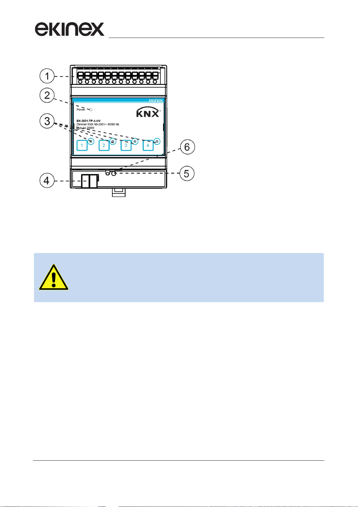
3. Switching, display and connection elements............................................................................................. 7
3.1 EK-GD2-TP-1-HV elements.................................................................................................................. 7
3.2 EK-GD1-TP-4-HV elements.................................................................................................................. 8
4. Configuration ............................................................................................................................................. 9
5. Commissioning .......................................................................................................................................... 9
5.1 Device reset........................................................................................................................................ 10
6. Function description................................................................................................................................. 10
7. Operation at power up............................................................................................................................. 11
8. Off-line operation ..................................................................................................................................... 12
9. Manual operation..................................................................................................................................... 12
10. Online operation ...................................................................................................................................... 13
10.1 Software operation.............................................................................................................................. 13
10.2 10.2 Status variables (Communication objects) ................................................................................. 13
10.3 Output management........................................................................................................................... 13
10.4 Channel status information................................................................................................................. 13
10.5 Dimming function................................................................................................................................ 14
10.5.1 Intensity limits.............................................................................................................................. 14
10.6 Switch On and Off delay..................................................................................................................... 15
10.7 Alarm information................................................................................................................................ 15
10.8 Staircase light function........................................................................................................................ 16
10.9 Logic function...................................................................................................................................... 19
10.10 Lock function................................................................................................................................ 22
10.11 Forcing function ........................................................................................................................... 23
10.12 Scene management..................................................................................................................... 24
10.13 Night function............................................................................................................................... 24
10.14 Operating hours / Energy consumption counter.......................................................................... 25
10.15 Initialisations ................................................................................................................................ 25
11. ETS application program......................................................................................................................... 27
11.1 About................................................................................................................................................... 29
11.2 General ............................................................................................................................................... 29
11.3 Channel configuration......................................................................................................................... 30
11.4 Channel x............................................................................................................................................ 32
11.4.1 Lock function............................................................................................................................... 34
11.4.2 Forced function............................................................................................................................ 35
11.4.3 Staircase light function................................................................................................................ 37
11.4.4 Logic function.............................................................................................................................. 38
11.4.5 Scenes function........................................................................................................................... 39
11.4.6 Night function .............................................................................................................................. 42
11.4.7 Counter function (energy and hours counter) ............................................................................. 42
11.5 Alarms................................................................................................................................................. 45
12. KNX communication objects summary.................................................................................................... 46

Application Manual
KNX EK-GD2-TP-1-HV / EK-GD1-TP-4-HV dimmer
Release 1.0 - Updated: 31/08/2023 MAEKGDxTPxHV_EN
© Ekinex S.p.A. –All rights reserved Page 3
13. Appendix.................................................................................................................................................. 47
13.1 Warnings............................................................................................................................................. 47
13.2 Return of defective products............................................................................................................... 47
13.2.1 Devices purchased directly from ekinex®.................................................................................... 47
13.2.2 Devices purchased through ekinex® resellers............................................................................. 47
13.3 Further information.............................................................................................................................. 47

Application Manual
KNX EK-GD2-TP-1-HV / EK-GD1-TP-4-HV dimmer
Release 1.0 - Updated: 31/08/2023 MAEKGDxTPxHV_EN
© Ekinex S.p.A. –All rights reserved Page 4
Release
Changes
Date
Author
Verified by
1.0
First issue
31/08/2023
G. Schiochet
C. Baldini

Application Manual
KNX EK-GD2-TP-1-HV / EK-GD1-TP-4-HV dimmer
Release 1.0 - Updated: 31/08/2023 MAEKGDxTPxHV_EN
© Ekinex S.p.A. –All rights reserved Page 5
1. Scope of the document
This manual describes the application details for version A1.0 of the following ekinex®devices:
EK-GD2-TP-1-HV: 90-230 Vac 1-channel phase-cut KNX dimmer.
EK-GD1-TP-4-HV: 90-230 Vac 4-channel phase cut KNX dimmer.
The document is intended for the system configurator as a description and reference guide for device functions
and application programming. For mechanical and electrical details of the installation device, please refer to
the technical data sheet of the device itself.
This application manual and the application programs for the ETS development environment are available for
download on the website www.ekinex.com.
Document
File name (## = release)
Versions
Device
release
Last update
Datasheet
STEKGD2TP1HV_EN.pdf
STEKGD1TP4HV_EN.pdf
1.0
A1.0
31/08/2023
Application Manual
MAEKGDxTPxHV_EN.pdf
1.0
ETS application file
APEKGD12TP##.knxprod
1.0

Application Manual
KNX EK-GD2-TP-1-HV / EK-GD1-TP-4-HV dimmer
Release 1.0 - Updated: 31/08/2023 MAEKGDxTPxHV_EN
© Ekinex S.p.A. –All rights reserved Page 6
2. Product description
The ekinex® KNX phase-cut dimmers powered by 90-230 Vac with 1 or 4 channels EK-GD2-TP-1-HV and EK-
GD1-TP-4-HV allow the brightness control of light loads with voltage 90 - 230 Vac at 50/60 Hz. The 1-channel
model has a maximum output power of 230 W, while the 4-channel model has a max. of 200 W for each
channel. The loads that can be used with the dimmers can be: incandescent lamps, mains voltage halogen
lamps, dimmable mains voltage LED lamps, dimmable mains voltage LED strips, switching power supplies for
dimmable phase cut LEDs. The dimmers cut the phase in Trailing Edge mode (on the falling edge). The devices
have an integrated bus communication module with SELV 30 Vdc voltage, KNX certified.
Throughout the manual, both devices will be referenced indifferently; the respective different
features will be pointed out wherever required.
The devices are equipped with an integrated interface module towards the KNX bus and are set up for
assembly:
on 35 mm profiled rail (according to EN 60715) using the plastic support supplied, in the case of the
1-channel model;
on unified DIN guide inside electrical panels, in the case of the 4-channel model.
Figure 1 - Support for DIN rail mounting of the 1-channel model
During operation, the module receives communication telegrams from the KNX bus sent by another device
(e.g. a manual control point, a sensor, a timer, etc.). These telegrams cause the activation or deactivation of
the outputs and the variation of the partitioning percentage, through the application of a series of utility functions
defined on the basis of programming.
For the operating logic, the device draws its power supply from the KNX bus line with a SELV voltage of 30V
d.c. and therefore does not require additional power sources. All the auxiliary voltages necessary for the
operation of the internal logic are produced by the device.
For further details and for the connection diagrams, refer to the STEKGD1TP1HV_EN.pdf and
STEKGD2TP4V_EN.pdf technical sheets available on the website www.ekinex.com.
i
i

Application Manual
KNX EK-GD2-TP-1-HV / EK-GD1-TP-4-HV dimmer
Release 1.0 - Updated: 31/08/2023 MAEKGDxTPxHV_EN
© Ekinex S.p.A. –All rights reserved Page 7
3. Switching, display and connection elements
The 1-channel device is equipped with:
Il dispositivo a 1 canale è dotato di:
a programming button and LED. This button is also used to carry out a load test, if the KNX bus is
connected;
screw terminal blocks for connecting the power supply for the outputs;
screw terminal blocks for connection of output loads;
plug-in terminal block for connecting the KNX bus line.
The 4-channel device is equipped with:
a programming button and LED;
a signaling LED for power supply presence;
one button and one LED for each channel, to carry out the local ON/OFF test of the output loads, even
in case the KNX bus is not present;
spring terminal blocks for connecting the power supply for the outputs;
spring terminal blocks for connection of output loads;
plug-in terminal block for connecting the KNX bus line.
3.1 EK-GD2-TP-1-HV elements
Figure 2 - Switching, display and connection elements for EK-
GD2-TP-1-HV
1. AC Phase / Neutral outputs
2. AC Phase / Neutral inputs
3. Not used
4. KNX bus terminal block
5. Programming and installation
test button
Programming LED (internal)

Application Manual
KNX EK-GD2-TP-1-HV / EK-GD1-TP-4-HV dimmer
Release 1.0 - Updated: 31/08/2023 MAEKGDxTPxHV_EN
© Ekinex S.p.A. –All rights reserved Page 8
3.2 EK-GD1-TP-4-HV elements
Warning:
Pay particular attention to identifying the correct connections, in order to
avoid short circuits and even fatal damage to the operator or to the
appliance.
Figure 3 - Switching, display and connection elements for EK-
GD1-TP-4-HV
1. 90-230 Vac supply Line / Neutral
inputs and channel outputs
2. Power ON LED
3. LEDs and membrane buttons for
channels 1, 2, 3, 4
4. KNX bus terminal block
5. Programming LED
Programming button

Application Manual
KNX EK-GD2-TP-1-HV / EK-GD1-TP-4-HV dimmer
Release 1.0 - Updated: 31/08/2023 MAEKGDxTPxHV_EN
© Ekinex S.p.A. –All rights reserved Page 9
4. Configuration
The functionality of the devices is determined by the settings made via software. These activities must be
carried out in compliance with the building automation system project carried out by a qualified professional.
In order to configure each device, the ETS5 development tool (or later versions) and the dedicated application
program APEKGD12HVTP##.knxprod are required; the latter can be downloaded from the ekinex website
www.ekinex.com.
The application program is unique for both models and allows you to access, within the ETS environment, the
choice of the type of device (1 or 4 channels) and the configuration of all the working parameters of the device.
The program must be loaded into ETS (alternatively it is possible to load the entire database of ekinex®
products in a single operation), after which all the device examples of the type considered can be added to the
project being defined.
The configurable parameters for the device will be described in detail in the following paragraphs.
The configuration can be, and usually will be, done completely off-line; the transfer of the set configuration to
the appliance will therefore take place in the programming phase, described in the following paragraph.
Product code
# of
channels
ETS Application program
(## = version)
Communication
objects
(max)
Group addresses
(max)
EK-GD1-TP-1-HV
1
APEKGD12HVTP##.knxprod
27
27
EK-GD2-TP-4-HV
4
102
102
The configuration and programming of KNX devices require specific knowledge; to acquire
this knowledge, it is recommended to attend the appropriate training courses at a center
certified by the KNX consortium.
For more information, visit www.knx.org website.
5. Commissioning
After the device configuration has been defined within the ETS project according to the user's requirements,
to carry out the programming it is necessary to carry out the following operations:
electrically connect the device, as described in the technical data sheet or in the instruction sheet, to
the KNX bus in the final destination system or in a reduced system, set up specifically for programming.
In any case, the system will contain an interface device towards the PC on which the KNX environment
is installed;
apply power to the bus;
activate the programming mode on the device by pressing the appropriate button located on the front.
The programming mode indication LED should turn on with a fixed light;
from the ETS environment, start programming (which in the case of first configuration must include
the physical address to be given to the device).
At the end of the program download, the device automatically returns to operating mode; the programming
LED must be off. The device is now programmed and ready for operation in the plant.
i

Application Manual
KNX EK-GD2-TP-1-HV / EK-GD1-TP-4-HV dimmer
Release 1.0 - Updated: 31/08/2023 MAEKGDxTPxHV_EN
© Ekinex S.p.A. –All rights reserved Page 10
5.1 Device reset
To reset the device, remove the connection to the bus network by removing the bus terminal from its seat.
Keeping the programming button pressed, reinsert the bus terminal in its seat; after about 10 seconds, the
programming LED flashes quickly. Release the programming button and extract the clamp again; the reset
has been performed. At this point it is necessary to carry out the addressing and configuration of the device
again using ETS.
Warning! The reset resets the device to the factory delivery state. The addressing and the
value of the parameters set in the configuration phase are lost.
6. Function description
The device is a partialization actuator (dimmer) for alternating current loads at mains voltage, which activates
and modulates its outputs according to the commands received via the bus.
It also includes several accessory functions such as:
ON/OFF control and regulation of light intensity of single or group lighting fixtures
Fade time on and off, minimum and maximum brightness level, linear or logarithmic regulation curve
settable by ETS
Soft or instant on and off, with settable delay
Configuration of behavior after power recovery, bus ON/OFF, download via ETS
Channels settable by ETS as independent, in parallel or with copy function from another channel
Status indication of the outputs via LED (only for model EK-GD1-TP-4-HV)
Block function, forced operation, staircase light, scenarios, night, counter and logic functions for each
channel, settable by ETS
Alarm for short circuit, open load and power failure
Auxiliary output function with status indication via KNX
Installer mode (only for EK-GD2-TP-1-HV, if KNX bus is present): pressing the programming button
for about 2 s activates/deactivates the flashing of the programming LED and the load every 1 s
Manual command via membrane buttons and for local ON/OFF test of channels 1-2-3-4 in case of
KNX bus absence (only for model EK-GD1-TP-4-HV). A button short press activates/deactivates the
load, pressing it for at least 2 seconds causes the load to flash approximately every 1 s
The functional blocks described are illustrated in the following figure, which is particularly important for
understanding which functions have priority over the others:

Application Manual
KNX EK-GD2-TP-1-HV / EK-GD1-TP-4-HV dimmer
Release 1.0 - Updated: 31/08/2023 MAEKGDxTPxHV_EN
© Ekinex S.p.A. –All rights reserved Page 11
Figure 4 - Functional blocks
The diagram above relates to the on - off switching functions of the outputs; some features, however, also
have an influence on the choking value. For example, scenario management also involves defining the
intensity value associated with the scenario. Full details are described in the paragraphs regarding the
individual functions.
7. Operation at power up
Upon connection of the bus, which also performs the power supply function for the logic, the device enters a
state of complete activity after a short period (of the order of tens of ms) necessary for reinitialisation. It is
possible to define a larger supplementary delay to avoid a traffic overload on the bus during the system start-
up phase.
An unprogrammed device does not perform any activity on the bus; however, the outputs can be individually
operated in manual mode (see below) via the membrane keyboard located on the front.
In the event of a voltage drop on the bus (voltage below 19 V for 1 s or more), the device shuts down; before
the power becomes insufficient, the state at the time of power off is stored internally.
When voltage is restored, the device resumes operation by restoring the status memorized when it was
switched off, except for those parameters for which a different behavior has been configured.

Application Manual
KNX EK-GD2-TP-1-HV / EK-GD1-TP-4-HV dimmer
Release 1.0 - Updated: 31/08/2023 MAEKGDxTPxHV_EN
© Ekinex S.p.A. –All rights reserved Page 12
The configuration options allow you to define the state of the device after some significant events. These
events are:
Switch on the device outputs, i.e. applying the mains voltage to supply the outputs;
Bus off, i.e. lack of KNX bus voltage
Bus on, i.e. application of the KNX bus voltage
Downloading a new configuration via ETS
Additional events are associated with specific functions such as output forcing and block function.
For each of these events, the status of the outputs can be selected from various combinations of values
according to how the outputs themselves are configured; these combinations of values will be indicated later
in the paragraphs dedicated to the description of the corresponding functions.
8. Off-line operation
Since the logic power supply is supplied by the KNX bus, a device not connected to the KNX bus has no
operating mode, even if the power supply voltage remains present.
9. Manual operation
The manual operation is an alternative possibility to driving the inputs via bus commands; this mode is intended
for test or maintenance situations.
The 4-channel model allows for manual control using the membrane buttons located on the front of the device.
Pressing each button allows you to carry out a local ON/OFF test of the load connected to the respective
channel, even in the absence of the KNX bus.
The 1-channel model also features an "installer mode" for carrying out the load test: pressing the programming
button for 2 seconds activates/deactivates the flashing of the programming and load LED every 1 s. In this
case, the KNX bus must be connected and active.

Application Manual
KNX EK-GD2-TP-1-HV / EK-GD1-TP-4-HV dimmer
Release 1.0 - Updated: 31/08/2023 MAEKGDxTPxHV_EN
© Ekinex S.p.A. –All rights reserved Page 13
10.Online operation
In addition to direct activation, the device is also equipped with auxiliary functions such as timing functions and
logic combination of inputs. These functions are described in detail in the following paragraphs.
10.1 Software operation
The activities performed by the software are the following:
update the internal status variables according to the telegrams on the KNX bus;
implement timing and other built-in features to determine the state of physical outputs;
activate the physical outputs according to the state of the logical outputs;
respond to requests on the bus relating to communication objects.
There are also particular events in correspondence with which additional functions can be activated. These
events are, for example, the failure or recovery of the bus or mains voltage and the loading of a new
configuration from the ETS (download).
10.2 10.2 Status variables (Communication objects)
The device status, and specifically of its interface elements (outputs) is based on state variables which are
automatically defined by the application program. When a status variable is assigned a group address, it
becomes to all effects a KNX communication object; as such, it assumes the usual characteristics of
communication objects, including for example the possibility of using the flags to establish how the modification
of the object impacts its transmission on the bus.
10.3 Output management
In the simplest case, three communication objects are made available for controlling each channel:
On-Off command, turns on or off the load connected to the channel;
Dimming command, modifies the partialization percentage (intensity) incrementally, i.e. with
commands of the type increase / decrease / stop;
Absolute setpoint control, allows you to directly specify the partialisation percentage.
10.4 Channel status information
Two communication objects for feedback relating to the status of each channel are available:
On/Off status: there is an object referring to each single output
Actual dimming value: contains the current unloading value the channel is set to.

Application Manual
KNX EK-GD2-TP-1-HV / EK-GD1-TP-4-HV dimmer
Release 1.0 - Updated: 31/08/2023 MAEKGDxTPxHV_EN
© Ekinex S.p.A. –All rights reserved Page 14
When these communication objects are defined, they are transmitted automatically at each change of status,
so that events can be generated at each effective change of the output. It is also possible to configure the
objects so that the transmission also takes place at regular intervals and to set the sending delay after the
KNX bus reset.
There is also a communication object called Auxiliary output status, which is set to ON if at least one load is
active, OFF if no load is controlled. It can be used to drive any ballasts for the lamps
When the on mode and/or the off mode are set to soft, the communication object indicating the
current dimming position provides as feedback the actual value it will reach at the end of the ramp.
Similarly during dimming, the final value (maximum value or minimum value) is provided as
feedback and only after the dimming command is released is the dimming percentage actually
reached provided as feedback.
10.5 Dimming function
The main parameters relating to the dimming function are as follows:
Curve type: linear or logarithmic.
Minimum / maximum dimming value: these are the values that define the maximum brightness
status of the lamp, those that will be associated with the "On" status (intensity and balance or color),
and the limits to be used for dimming operations.
The more precise description of the limits for the various modes can be found in the following paragraph.
Full range dimming time: it refers to the complete transition from 0% to 100%. If variations of lower
amplitude are defined (e.g. in sequences), the times will be proportionally shorter.
Different times can be defined for the following transitions, for each channel:
- Absolute dimming (i.e. when the percentage of intensity to be achieved is controlled directly)
- Relative dimming (ie the one obtained with commands such as "raise" / "lower")
- Switching on (upon receiving an “On” command)
1
- Shutdown (upon receiving an “Off” command)
10.5.1 Intensity limits
It is possible to define some parameters to limit the range of intensities, both for technical purposes (e.g. flicker
prevention or overdriving) and for functional purposes (e.g. optimization of the usable ranges or of the desired
maximum or minimum luminosities).
The Minimum dimming value and Maximum dimming value parameters allow you to limit the dimming
range between a minimum and a maximum value, calculated as a percentage of the maximum available
dynamics. After setting these numbers, the regulation values will be normalized with respect to the two new
1
The “On” dimming time is applied even if the intensity to be reached is not equal to 100%, for example with
a restart command when it is set as the “Previous” restart level.
i

Application Manual
KNX EK-GD2-TP-1-HV / EK-GD1-TP-4-HV dimmer
Release 1.0 - Updated: 31/08/2023 MAEKGDxTPxHV_EN
© Ekinex S.p.A. –All rights reserved Page 15
limits, with the new 0% which will correspond to the minimum regulation and the new 100% which will
correspond to the maximum regulation.
10.6 Switch On and Off delay
It is possible to set delays between the command to change the state of an output and the actual switching. A
separate delay time can be set for each transition in activation and in deactivation (or, with electrotechnical
terminology, in energization and in deactivation); these times in the following figure are indicated respectively
as Ton and Toff.
These delays apply to switching via direct command and/or logical objects, but not to switching caused by
other functions (e.g. staircase lighting or scene).
Figure 5 - Switching delays
10.7 Alarm information
Concerning the alarm / fault indicators at the device level, the following communication objects are available:
Power alarm status. It is activated if the power stage supply voltage is missing.
Short circuit alarm (one for each channel), activated if a condition of excessive current absorption is
detected on a specific channel.
For the same purpose, 4 further objects related to the individual channels are available.
Open load alarm ((one for each channel), activated if no load is detected on the corresponding
channel.
There is a specific parameter to set whether, when one of the alarms is active, it should be cyclically transmitted
on the bus and at what interval.

Application Manual
KNX EK-GD2-TP-1-HV / EK-GD1-TP-4-HV dimmer
Release 1.0 - Updated: 31/08/2023 MAEKGDxTPxHV_EN
© Ekinex S.p.A. –All rights reserved Page 16
10.8 Staircase light function
The intent of this function is to allow simple and flexible management of the timing of staircase lights or utilities
with similar characteristics. The special requirements are as follows:
the light is activated by a "Start" command (for example via a button or a presence sensor), and
normally it must remain on for a programmed base time;
there must be the possibility of activating a "Stop" command (manual OFF), again via a button or other
event, which allows the light to be switched off before the programmed time (e.g. when a sensor
detects that the person passing by has left the building);
there must be the possibility of allowing another "Start" command, received during timing, to restart
the time count (Retriggerable);
a further function, called "pre-warning", can cause the temporary switching off of the light at a certain
distance from the end of the time to warn of the imminent deadline; both of these times (duration of
the interruption and distance from the end) can be set.
The prewarning time must be shorter than the staircase lighting time (TP-W < TS) and the
interruption time must be shorter than the prewarning time (TI< TP-W).
The on / off delay times set have no influence on the staircase light function.
A timing in progress will be terminated by a device reset (bus voltage failure and recovery or
reprogramming from ETS) or by the use of any function that influences the output (e.g. direct
command, forced command, logic function, scene recall ), even if the on / off value of the output
is not changed by the used function.
In the event of forced termination of the timing, the output value remains the one active at the
time of termination; this also applies if the termination occurs during the pre-warning time.
The following figures illustrate how the manual off function works:
i

Application Manual
KNX EK-GD2-TP-1-HV / EK-GD1-TP-4-HV dimmer
Release 1.0 - Updated: 31/08/2023 MAEKGDxTPxHV_EN
© Ekinex S.p.A. –All rights reserved Page 17
Figure 6 - Manual switch-off function
The following figures illustrate how the Restart (Retriggerable) function works:

Application Manual
KNX EK-GD2-TP-1-HV / EK-GD1-TP-4-HV dimmer
Release 1.0 - Updated: 31/08/2023 MAEKGDxTPxHV_EN
© Ekinex S.p.A. –All rights reserved Page 18
Figure 7 - Retrigger feature
The following figures illustrate how the pre-warning function works:

Application Manual
KNX EK-GD2-TP-1-HV / EK-GD1-TP-4-HV dimmer
Release 1.0 - Updated: 31/08/2023 MAEKGDxTPxHV_EN
© Ekinex S.p.A. –All rights reserved Page 19
Figure 8 - Pre-warning feature
10.9 Logic function
The device has the possibility of conditioning the status of the outputs with the application of a simple logic
block.

Application Manual
KNX EK-GD2-TP-1-HV / EK-GD1-TP-4-HV dimmer
Release 1.0 - Updated: 31/08/2023 MAEKGDxTPxHV_EN
© Ekinex S.p.A. –All rights reserved Page 20
The direct command can be applied to the input of a block with a logical operation selectable between AND,
OR or Exclusive OR. The same block can be supplied as inputs up to 8 further values, belonging to
communication objects accessible via bus to other external devices. Each of these objects can be individually
applied, if desired, a negation operator that inverts its value.
The inputs formed by the objects are then logically combined as shown in the following figure:
Figure 9 - Logic function
The logic block, on the right in the figure, has the following function depending on the selected operation:
OR –the output is ON when at least one of the inputs is ON;
AND –the output is ON only if all inputs are ON;
XOR –output is ON if an odd number of inputs are ON.
This last function is more intuitive if you refer to only two inputs: in this case, the output is ON when one input
or the other are ON, but not together.
It should be noted that, in this description, "input" and "output" refer only to the logic block; for the purposes of
device operation, the effective "inputs" are given by the communication objects, therefore the possible
activation of the inverters must also be considered.
This structure allows to implement also logical combinations of discrete complexity; moreover, a more stringent
programmability would have added excessive complexity and would therefore have been outside the scope of
obtaining a simple-to-use structure.
This manual suits for next models
1
Table of contents
Other Ekinex Dimmer manuals

Ekinex
Ekinex EK-GA1-TP Instructions for use

Ekinex
Ekinex EK-GM2-DL User manual

Ekinex
Ekinex EK-GL1-DL User manual

Ekinex
Ekinex EK-GD1-DL-4-HV User manual

Ekinex
Ekinex EK-GO1-DL User manual

Ekinex
Ekinex EK-GH1-DL User manual

Ekinex
Ekinex EK-GD2-TP-1-HV User manual

Ekinex
Ekinex KNX 90-230 Operating and safety instructions