SSD 605C User manual

Copyright 2005 SSD Drives Limited (formerly Eurotherm Drives Limited)
All rights strictly reserved. No part of this document may be stored in a retrieval system, or transmitted in any form or by
any means to persons not employed by an SSD Drives company without written permission from SSD Drives Ltd.
Although every effort has been taken to ensure the accuracy of this document it may be necessary, without notice, to
make amendments or correct omissions. SSD Drives cannot accept responsibility for damage, injury, or expenses
resulting therefrom.
605C
Frequency
Inverter
Product Manual
HA465013U001 Issue 8
Compatible with Version 5.x Software

Cont.2
WARRANTY
SSD Drives warrants the goods against defects in design, materials and workmanship
for the period of 12 months from the date of delivery on the terms
detailed in SSD Drives Standard Conditions of Sale IA058393C.
SSD Drives reserves the right to change the content and product specification without notice.

Cont.3
Requirements
IMPORTANT: Please read this information BEFORE installing the equipment.
Intended Users
This manual is to be made available to all persons who are required to install, configure or
service equipment described herein, or any other associated operation.
The information given is intended to highlight safety issues, and to enable the user to obtain
maximum benefit from the equipment.
Complete the following table for future reference detailing how the unit is to be installed and
used.
INSTALLATION DETAILS
Serial Number
(see product label)
Where installed
(for your own
information)
Unit used as a:
(refer to Certification
for the Inverter)
RComponent RRelevant Apparatus
Unit fitted: RWall-mounted REnclosure
Application Area
The equipment described is intended for industrial motor speed control utilising AC induction or
AC synchronous machines.
Personnel
Installation, operation and maintenance of the equipment should be carried out by qualified
personnel. A qualified person is someone who is technically competent and familiar with all
safety information and established safety practices; with the installation process, operation and
maintenance of this equipment; and with all the hazards involved.
!
Safety Information

Cont.4
Hazards
WARNING!
This equipment can endanger life through rotating machinery and high voltages.
Failure to observe the following will constitute an ELECTRICAL SHOCK HAZARD.
This is a product of the restricted sales distribution class according to IEC 61800-3.
In a domestic environment this product may cause radio interference in which case
the user may be required to take adequate measures.
This product is designated as “professional equipment” as defined in EN61000-3-2.
Permission of the supply authority shall be obtained before connection to the low
voltage supply.
•The equipment must be permanently earthed due to the high earth leakage current.
•The drive motor must be connected to an appropriate safety earth.
•The equipment contains high value capacitors which take time to discharge after removal of
the mains supply.
•Before working on the equipment, ensure isolation of the mains supply from terminals L1,
L2 and L3. Wait for at least 3 minutes for the dc link terminals (DC+ and DC-) to discharge
to safe voltage levels (<50V). Measure the DC+ and DC- terminal voltage with a meter to
confirm that the voltage is less than 50V.
•Never perform high voltage resistance checks on the wiring without first disconnecting the
drive from the circuit being tested.
•When replacing a drive in an application and before returning to use, it is essential that all
user defined parameters for the product’s operation are correctly installed.
•This equipment contains electrostatic discharge (ESD) sensitive parts. Observe static
control precautions when handling, installing and servicing this product.
IMPORTANT: Metal parts may reach a temperature of 90 degrees centigrade in operation.
Application Risk
The specifications, processes and circuitry described herein are for guidance only and may need
to be adapted to the user’s specific application. Refer to page 3-1.
SSD Drives does not guarantee the suitability of the equipment described in this Manual for
individual applications.
Risk Assessment
Under fault conditions, power loss or other operating conditions not intended, the equipment
may not operate as specified. In particular:
•The motor speed may not be controlled
•The direction of rotation of the motor may not be controlled
•The motor may be energised
Guards
The user must provide guarding and /or additional safety systems to prevent risk of injury and
electric shock.
Protective Insulation
•All control and signal terminals are SELV, i.e. protected by double insulation. Ensure all
wiring is rated for the highest system voltage.
Note: Thermal sensors contained within the motor must be double insulated.
•All exposed metalwork in the Inverter is protected by basic insulation and bonding to a
safety earth.
RCDs
These are not recommended for use with this product but ,where their use is mandatory, only
Type B RCDs should be used.
!
Safety Information

Contents
Contents Page
Cont.5
Chapter 1 GETTING STARTED
Introduction ..................................................................................................1-1
Optional Equipment ................................................................................................1-1
Equipment Inspection ................................................................................... 1-2
About this Manual ........................................................................................1-2
Initial Steps .............................................................................................................1-2
How the Manual is Organised .................................................................................1-2
•Application Block Diagrams ..................................................................1-3
•Quick-Start Guide.................................................................................1-3
•Information for Users without an Operator Station..................................1-3
Chapter 2 AN OVERVIEW OF THE INVERTER
Component Identification ............................................................................. 2-1
Control Features ........................................................................................... 2-2
Understanding the Product Code .................................................................2-3
Functional Overview ..................................................................................... 2-4
Power Board ...........................................................................................................2-4
Control Board.........................................................................................................2-4
•Processor .............................................................................................2-4
•Technology Option Interface .................................................................2-4
•Operator Station Interface.....................................................................2-4
Chapter 3 INSTALLING THE INVERTER
Mechanical Installation ................................................................................ 3-1
Mounting the Inverter ..............................................................................................3-1
Minimum Air Clearances .........................................................................................3-1
•Ventilation............................................................................................3-1
•Air Clearance: Cubicle-Mount Product/Application .................................3-3
•Air Clearance: Wall-Mount Product/Application......................................3-3
Electrical Installation .................................................................................... 3-4
Wiring the Inverter ..................................................................................................3-4
•Protective Earth (PE) Connections ...........................................................3-6
•Power Wiring Connections ....................................................................3-6
•Control Wiring Connections ..................................................................3-7
Optional Equipment ..................................................................................... 3-8
•Fitting the Remote 6901 Operator Station .............................................. 3-8
•Top Cover ............................................................................................3-9
•Technology Options............................................................................3-10
•External Brake Resistor ........................................................................3-11
•External AC Supply EMC Filter .............................................................3-12

Contents
Contents Page
Cont.6
•Output Contactors ..............................................................................3-13
•Earth Fault Monitoring Systems............................................................3-13
•Line Chokes (input) .............................................................................3-14
•AC Motor Choke (output) ....................................................................3-14
Chapter 4 OPERATING THE INVERTER
Pre-Operation Checks .................................................................................. 4-1
Control Philosophy........................................................................................4-2
Start/Stop and Speed Control....................................................................... 4-2
•Selecting Local or Remote Control .........................................................4-3
Start-up Routines.......................................................................................... 4-4
Remote Control using Control Terminals (default set-up) ...........................................4-4
•Reading the Status LEDs ........................................................................4-4
Local Control using the Operator Station .......................................................................4-5
Setting-up the Inverter................................................................................. 4-5
Quick Set-up as an Open-loop Inverter (V/F fluxing) .................................................4-5
Set-up using the Sensorless Vector Fluxing Mode ......................................................4-6
The Autotune Feature ..............................................................................................4-6
Manual Tuning .......................................................................................................4-7
•Tuning using the Motor Equivalent Circuit ..............................................4-7
•Tuning using a Simple Tuning Sequence ................................................4-7
Tuning Difficulties....................................................................................................4-8
The Start/Stop Mode Explained ....................................................................4-8
Starting and Stopping Methods ...................................................................4-9
Normal Stopping Methods.......................................................................................4-9
•Ramp to Stop........................................................................................4-9
•Coast to Stop......................................................................................4-10
Advanced Stopping Methods .................................................................................4-10
•Forced Fast Stop .................................................................................4-10
•Forced Coast Stop ..............................................................................4-11
•The Trip Condition..............................................................................4-11
•Logic Stopping....................................................................................4-11
Normal Starting Method........................................................................................4-12
Advanced Starting Methods ...................................................................................4-12
•Starting Several Inverters Simultaneously..............................................4-12
•Single Wire Logic Starting....................................................................4-12
•Two Wire Logic Starting.......................................................................4-13
•Three Wire Logic Starting ....................................................................4-13

Contents
Contents Page
Cont.7
Chapter 5 THE OPERATOR STATION
Connecting the Operator Station .................................................................5-1
•Welcome Screen...................................................................................5-1
Customising the Operator Station ................................................................ 5-1
Controlling the Drive using the Operator Station .......................................5-2
Control Keys ...........................................................................................................5-2
•Keys for Programming the Drive ............................................................5-2
•Keys for Operating the Drive Locally ......................................................5-2
LED Indications .......................................................................................................5-3
The Menu System.......................................................................................... 5-4
Navigating the Menu System....................................................................................5-4
•The Menu System Map..........................................................................5-5
Changing a Parameter Value...................................................................................5-6
What do the Symbols mean next to some Parameters?..............................................5-6
•Parameter Status Information →←=.................................................5-6
•Expanded Menu Information >>..........................................................5-6
Alert Message Displays............................................................................................5-7
The PROG Key ........................................................................................................5-7
The L/R Key ............................................................................................................5-7
The MMI DIAGNOSTICS Menu ...................................................................... 5-8
Special Menu Features ...............................................................................5-10
Menu Shortcuts and Special Key Combinations.......................................................5-10
•Quick Link Information .......................................................................5-10
•Quick Save to Memory........................................................................5-10
•Changing the Display Language..........................................................5-10
•Quick Drive Copy ...............................................................................5-10
•Changing the Product Code ................................................................5-11
•Quick Restore Default .........................................................................5-11
Menu Viewing Levels .............................................................................................5-11
•Startup Screen Timeouts ......................................................................5-11
Selecting the Display Language..............................................................................5-12
Control Key Enable/Disable...................................................................................5-12
Password Protection ..............................................................................................5-12
•To Activate Password Protection ...........................................................5-12
•To Deactivate Password Protection.......................................................5-12
Selecting Parameters for the Operator Menu ..........................................................5-13
•Selecting a Startup Screen ...................................................................5-13
•Customising the Welcome Screen ........................................................5-13
•Creating Custom Screens ....................................................................5-14

Contents
Contents Page
Cont.8
How to Save, Restore and Copy your Settings............................................ 5-14
Saving Your Application ........................................................................................5-14
Restoring Saved Settings ........................................................................................5-14
Copying an Application .........................................................................................5-14
•Transferring Your Application to Another Inverter .................................5-14
•Backing-up Your Application ...............................................................5-15
Chapter 6 PROGRAMMING YOUR APPLICATION
Introducing the Macro ..................................................................................6-1
Programming with Block Diagrams .............................................................6-1
Modifying a Block Diagram .....................................................................................6-1
•Configuration and Parameterisation Modes ...........................................6-1
•Making and Breaking Links in Configuration Mode ................................6-1
•Programming Rules ..............................................................................6-2
•Execution Rules .....................................................................................6-2
•Saving Your Modifications .....................................................................6-3
Understanding the Function Block Description ..........................................................6-3
•MMI Menu Maps ..................................................................................6-3
Hexadecimal Representation of Trips........................................................................6-4
Function Block Descriptions.......................................................................... 6-5
•ANALOG DIGIN...................................................................................6-6
•ANALOG INPUT ...................................................................................6-8
•ANALOG OUTPUT .............................................................................6-11
•AUTO RESTART...................................................................................6-13
•AUTOTUNE........................................................................................6-15
•BRAKE CONTROL...............................................................................6-16
•COMMS CONTROL............................................................................6-17
•CURRENT FEEDBACK..........................................................................6-18
•CURRENT LIMIT ..................................................................................6-20
•CUSTOM SCREEN ..............................................................................6-21
•DEMULTIPLEXER .................................................................................6-23
•DIGITAL INPUT...................................................................................6-24
•DIGITAL OUTPUT ...............................................................................6-25
•DYNAMIC BRAKING ...........................................................................6-26
•ENCODER..........................................................................................6-27
•FLUXING............................................................................................6-28
•FLYCATCHING...................................................................................6-30
•INJ BRAKING......................................................................................6-32
•I/O TRIPS ...........................................................................................6-33
•I*t TRIP ...............................................................................................6-34
•JOG ..................................................................................................6-35
•LOCAL CONTROL..............................................................................6-36
•LOGIC FUNCTION ............................................................................6-37
•MINIMUM SPEED................................................................................6-41
•MULTIPLEXER......................................................................................6-42

Contents
Contents Page
Cont.9
•OPERATOR MENU..............................................................................6-43
•OP STATION ......................................................................................6-44
•PASSWORD........................................................................................6-46
•PATTERN GEN....................................................................................6-47
•PID ....................................................................................................6-48
•PRESET ...............................................................................................6-50
•RAISE/LOWER.....................................................................................6-52
•REFERENCE ........................................................................................6-53
•SEQUENCING LOGIC........................................................................6-55
•SETPOINT SCALE................................................................................6-57
•SKIP FREQUENCIES ............................................................................6-58
•SLEW RATE LIMIT ................................................................................6-60
•SLIP COMP.........................................................................................6-61
•STABILISATION...................................................................................6-62
•STALL TRIP..........................................................................................6-63
•STOP .................................................................................................6-64
•SYSTEM PORT (P3)..............................................................................6-65
•SYSTEM RAMP ....................................................................................6-66
•TEC OPTION......................................................................................6-68
•TRIPS HISTORY ...................................................................................6-69
•TRIPS STATUS .....................................................................................6-70
•UNDERLAP COMP ..............................................................................6-72
•VALUE FUNCTION .............................................................................6-73
•VECTOR FLUXING ..............................................................................6-80
•VOLTAGE CONTROL..........................................................................6-81
•ZERO SPEED.......................................................................................6-82
Motor-Specific Parameters ......................................................................... 6-83
Quadratic Torque Selection ........................................................................ 6-84
Chapter 7 TRIPS AND FAULT FINDING
Trips ..............................................................................................................7-1
What Happens when a Trip Occurs..........................................................................7-1
•Inverter Indications................................................................................7-1
•Operator Station Indications (when connected).......................................7-1
Resetting a Trip Condition........................................................................................7-1
Using the Operator Station to Manage Trips.............................................................7-2
•Trip Messages ......................................................................................7-2
•Automatic Trip Reset .............................................................................7-3
•Setting Trip Conditions ..........................................................................7-3
•Viewing Trip Conditions ........................................................................7-3
Checksum Fail ........................................................................................................7-4
•Inverter Indications................................................................................7-4
•Operator Station Indications (when connected).......................................7-4
Fault Finding................................................................................................. 7-4

Contents
Contents Page
Cont.10
Chapter 8 ROUTINE MAINTENANCE AND REPAIR
Routine Maintenance....................................................................................8-1
Repair ...........................................................................................................8-1
Saving Your Application Data ..................................................................................8-1
Returning the Unit to SSD Drives ..............................................................................8-1
Disposal .................................................................................................................8-1
Chapter 9 SEQUENCING LOGIC
Principle State Machine ................................................................................9-1
Main Sequencing States...........................................................................................9-1
State Outputs of the SEQUENCING LOGIC Function Block .......................................9-1
Transition of States..................................................................................................9-2
State Diagram ........................................................................................................9-3
External Control of the Inverter....................................................................9-4
Communications Command....................................................................................9-4
•Example Commands .................................................................9-5
Communications Status ...........................................................................................9-6
Chapter 10 PARAMETER SPECIFICATION
Specification Table: Tag Number Order..................................................... 10-2
Product-Related Default Values ...............................................................10-19
•Language Dependant Defaults ..........................................................10-19
•AC Supply Voltage and Power Rating Dependant Defaults ..................10-20
Chapter 11 TECHNICAL SPECIFICATIONS
605C Model Recognition.......................................................................................11-1
Environmental Details............................................................................................11-1
Earthing/Safety Details ..........................................................................................11-2
Terminal Block Wire Sizes......................................................................................11-2
Electrical Ratings ...................................................................................................11-3
Cabling Requirements for EMC Compliance...........................................................11-4
EMC Compliance..................................................................................................11-4
External AC Supply (RFI) Filters...............................................................................11-4
Internal Dynamic Brake Switch...............................................................................11-5
Control Terminals .................................................................................................11-6
Analog Inputs/Outputs ..........................................................................................11-7
Digital Inputs ........................................................................................................11-7
Digital Outputs .....................................................................................................11-7
Supply Harmonic Analysis......................................................................................11-8

Contents
Contents Page
Cont.11
Chapter 12 CERTIFICATION FOR THE INVERTER
Requirements for EMC Compliance ............................................................12-1
Minimising Radiated Emissions ..............................................................................12-1
Earthing Requirements...........................................................................................12-1
•Protective Earth (PE) Connections .........................................................12-1
•EMC Earth Connections ......................................................................12-1
Cabling Requirements ...........................................................................................12-2
•Planning Cable Runs...........................................................................12-2
•Increasing Motor Cable Length............................................................12-2
EMC Installation Options.......................................................................................12-3
•Screening & Earthing (wall mounted, Class A) ......................................12-3
•Screening & Earthing (cubicle mounted, Class B) ..................................12-3
•Star Point Earthing ..............................................................................12-5
•Sensitive Equipment ............................................................................12-6
Requirements for UL Compliance ...............................................................12-7
•Solid-State Motor Overload Protection .................................................12-7
•Short Circuit Rating .............................................................................12-7
•Solid-State Short-Circuit Protection.......................................................12-7
•Recommended Branch Circuit Protection..............................................12-7
•Motor Base Frequency.........................................................................12-7
•Field Wiring Temperature Rating .........................................................12-7
•Field Wiring Terminal Markings...........................................................12-7
•Power Wiring Terminals ......................................................................12-7
•Terminal Tightening Torque ................................................................12-7
•Field Grounding Terminals..................................................................12-8
•Operating Ambient Temperature .........................................................12-8
•Direct Wall-Mountable Models ............................................................12-8
European Directives and the CE Mark........................................................ 12-9
CE Marking for Low Voltage Directive ....................................................................12-9
CE Marking for EMC - Who is Responsible? ...........................................................12-9
•Legal Requirements for CE Marking...................................................12-10
•Applying for CE Marking for EMC......................................................12-10
Which Standards Apply?......................................................................................12-10
•Power Drive Product Specific or Generic Standards.............................12-10
Certificates .........................................................................................................12-16

Contents
Contents Page
Cont.12
Chapter 13 APPLICATION NOTES
Synchronous Motor Control ........................................................................ 13-1
Brake Motors .............................................................................................. 13-1
Using Line Chokes ...................................................................................... 13-2
Using Output Contactors............................................................................. 13-2
Using Motor Chokes ...................................................................................13-2
Using Multiple Motors on a Single Drive....................................................13-3
Dynamic Braking ........................................................................................ 13-3
Brake Resistor Selection .........................................................................................13-4
High Starting Torque .................................................................................. 13-5
Chapter 14 SERIAL COMMUNICATIONS
Communications Technology Option .......................................................... 14-1
ConfigEd Lite ........................................................................................................14-1
Connection to the P3 Port ...........................................................................14-1
Chapter 15 APPLICATION MACROS
The Default Application .............................................................................. 15-1
How to Load a Macro.................................................................................. 15-1
Macro Descriptions ..................................................................................... 15-1
Macro 0 ...............................................................................................................15-1
Macro 1: Basic Speed Control (default) ..................................................................15-3
Macro 2: Run Forward/Run Reverse .......................................................................15-5
Macro 3: Raise/Lower Trim....................................................................................15-7
Macro 4: Process PID ............................................................................................15-9
Macro 5: Preset Speeds .......................................................................................15-11
Macro 6: Closed-Loop Speed Feedback ...............................................................15-13
Macro 99: 584S Compatible Application .............................................................15-15
General Wiring Diagram for Macro 99 ................................................................15-18
Macro Control Blocks ..........................................................................................15-19
Macro User Blocks ..............................................................................................15-20

Getting Started 1-1
605C Frequency Inverter
1GETTING STARTED
Introduction
The 605C Frequency Inverter is designed for speed control of standard 3-phase induction
motors. It is available in a range of ratings for constant torque and quadratic torque applications.
This dual mode feature is available on all 605C models and provides a cost effective solution to
general industrial applications, as well as the control of pumps and fans.
•The unit can be controlled remotely using configurable analog and digital inputs and
outputs, requiring no optional equipment.
•Controlling the unit locally using the 6051 Operator Station, or remotely using ConfigEd
Lite (or other suitable PC programming tool) and the Technology Options, gives access to
parameters, diagnostic messages, trip settings and full application programming. Other
features also become available, such as the advanced sensorless vector control scheme
which gives high torque, low speed operation; selectable switching frequencies; and a
unique Quiet Pattern control system that minimises audible noise from the motor.
Technology Options can be fitted to the Inverter to give serial communications, closed loop
speed control, and the factory-fitted dynamic braking functions.
IMPORTANT: Motors used must be suitable for inverter duty.
Optional Equipment
Item Part Number
6051 Operator Station
A plug-in unit providing control, monitoring and programming
capabilities
6051
Panel Mounting Kit for the 6051 Operator Station 6052
TB1 Comms Technology Option
This is a plug-in unit. Versions are available to provide Link2,
Profibus, Devicenet or RS422/485 serial comms.
Refer to SSD Drives for available protocols.
6055/option
TB2 Speed Feedback Technology Option
This is a plug-in unit. It provides speed feedback plus RS422 re-
transmit. Feedback options are TTL Encoder (RS422), HTL Encoder
(15V), Analog Tach, Sinusoidal Encoder, Resolver, Microtach.
6054/option
External Brake Resistor
A standard heat resistor.
CZ463068
CZ388396
External AC Supply (RFI) Filter Refer to Chapter 11:
“External AC Supply
(RFI) Filters” for Part
Numbers
Top Cover (UL Type 1 / IP4x)
A protective cover fitted to wall-mounted units to give improved
compliance ratings
B0470230U007 (top)
FB038K12 (screw)
ConfigEd Lite
SSD Drives’ Windows-based block programming software
Order by name
EMC Installation Guidelines for Modules and Systems
A SSD Drives application manual detailing EMC requirements
HA388879
Table 1-1 Optional Equipment

1-2 Getting Started
605C Frequency Inverter
Equipment Inspection
•Check for signs of transit damage
•Check the product code on the rating label conforms to your requirement.
If the unit is not being installed immediately, store the unit in a well-ventilated place away from
high temperatures, humidity, dust, or metal particles.
Refer to Chapter 2: “An Overview of the Inverter” to check the rating label/product code.
Refer to Chapter 8: “Routine Maintenance and Repair” for information on returning damaged
goods.
About this Manual
This manual is intended for use by the installer, user and programmer of the 605C Inverter. It
assumes a reasonable level of understanding in these three disciplines.
Note: Please read all Safety Information before proceeding with the installation and operation
of this unit.
Enter the “Model No” from the rating label into the table at the front of this manual. There is
also a column for you to record your application’s parameter settings in the table in Chapter 10.
It is important that you pass this manual on to any new user of this unit.
Initial Steps
Use the manual to help you plan the following:
Installation
Know your requirements:
•certification requirements, EMC/UL conformance
•wall-mount or enclosure?
•conformance with local installation requirements
•supply and cabling requirements
Operation
Know your operator:
•how is it to be operated, local and/or remote?
•what level of user is going to operate the unit?
•decide on the best menu level for the Operator Station
Programming (Operator Station or suitable PC programming tool only)
Know your application:
•install the most appropriate macro
•plan your “block diagram programming”
•enter a password to guard against illicit or accidental changes
•learn how to back-up your application data
•customise the Operator Station to the application
How the Manual is Organised
The manual is divided into chapters and paragraphs. Page numbering restarts with every
chapter, i.e. 5-3 is Chapter 5, page 3.
This manual describes the 605C Inverter.
Getting Started 1-3
605C Frequency Inverter
Application Block Diagrams
You will find these at the rear of the manual. The pages unfold to show a complete block
diagram, these will become your programming tool as you become more familiar with the 605’s
software.
Quick-Start Guide
Chapters 3 and 4
install and run
the product
details the
Operator Station
and menu system
Chapter 5
Chapter 11
technical details
holds many of the
Information for Users without an Operator Station
This symbol identifies important text for users operating the 605C Inverter using the default
(factory) set-up.
If the text is italic, such as this, then the information is especially for users without the Operator
Station or suitable PC programming tool.
DEFAULT

1-4 Getting Started
605C Frequency Inverter
An Overview of the Inverter 2-1
605C Frequency Inverter
2AN OVERVIEW OF THE INVERTER
Component Identification
2
78
15 14
4
13
12
9
5
10
11
Front View (with items removed)
1
6
3
16
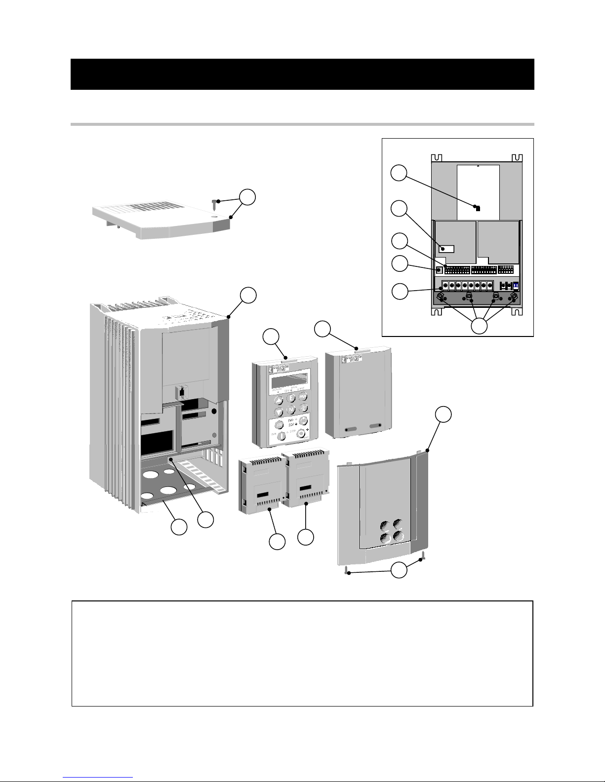
Figure 2-1 View of Component Parts
1Main inverter assembly 9Control terminals
2Top cover and screw (optional) 10 Power terminals
3Terminal cover retaining screw 11 Earthing points
4Terminal cover 12 RS232 programming port
5Remote operator station port 13 Gland plate
6Power terminal shield 14 Comms technology option (optional)
76051 operator station (optional) 15 Speed feedback technology option (optional)
8Blank cover 16 Configuration switches SW1 & SW2

2-2 An Overview of the Inverter
605C Frequency Inverter
Control Features
The 605C Inverter is fully-featured when controlled using the optional Operator Station (or a
suitable PC programming tool).
The `General’ control features below are not available when the unit is controlled using the
analog and digital inputs and outputs.
General Output Frequency Selectable 0-120Hz, 240Hz or 480Hz
Switching Frequency Constant Torque: selectable 3kHz or 6kHz depending on
power rating
Quadratic Torque: 3kHz for all units
Voltage Boost 0-25% (Fixed or Auto Boost)
Flux Control 1. V/F control with linear or fan law profile
2. Sensorless vector with automatic flux control and slip
compensation
Slip Compensation Compensates for motor slip for varying loads
Skip Frequencies 4 skip frequencies with adjustable skip band width
Preset Speeds 8 presets with programmable ramp rates
Stopping Modes Ramp, ramp with hold, coast, dc injection, fast stop
Ramps Symmetric or asymmetric ramp up and down rates
Raise/Lower Programmable MOP function
Jog Programmable jog speed
Logic Functions 10 programmable 3 input logic function blocks
performing NOT, AND, NAND, OR, NOR and XOR
functions
Value Functions 10 programmable 3 input value function blocks
performing IF, ABS, SWITCH, RATIO, ADD, SUB, RATIO,
TRACK/HOLD, and BINARY DECODE functions
Diagnostics Full diagnostic and monitoring facilities
Protection Trip Conditions Output short line to line, and line to earth
Overcurrent > 220%
I x t overload 50-105% (adjustable)
Heatsink overtemperature
Motor Thermistor overtemperature
Overvoltage and undervoltage
Current Limits Adjustable 50%-150%
180% shock load limit
Voltage/ Frequency
Profile
Constant torque
Fan Law
Inputs/
Outputs
Analog Inputs 4 user-configurable:
Speed setpoint/trim ±10V, 0-10V, 2-10V, 0-5V, 1-5V
Speed setpoint 4-20, 20-4, 0-20 or 20-0mA
Current loop 4-20, 20-4, 0-20 or 20-0mA
Torque limit 0-10V
Analog Outputs 2 user-configurable:
Speed 0-10V and 0-20mA
Load ±10V
Digital Inputs 8 x 24V dc inputs (user-configurable)
Digital Outputs 3 relay contacts (volt-free)
Table 2-1 Control Features
DEFAULT
An Overview of the Inverter 2-3
605C Frequency Inverter
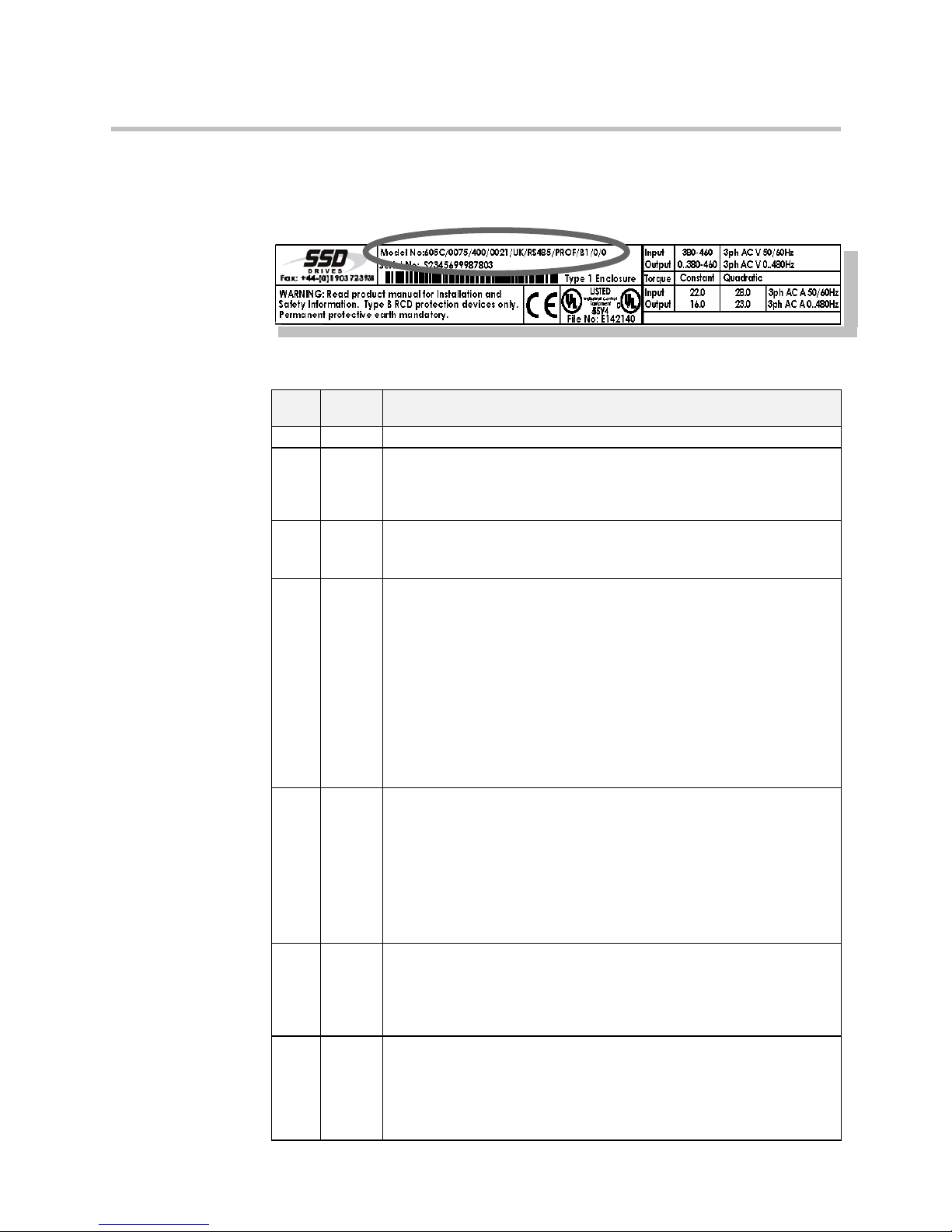
Understanding the Product Code
The 605C unit is fully identified using a ten block alphanumeric code which records how the
Inverter was calibrated, and its various settings when despatched from the factory.
The Product Code appears as the “Model No.”. Each block of the Product Code is identified as
below:
Note: The Language field controls the default setting for the BASE FREQUENCY parameter.
Block
No.
Variable Description
1 605C Generic product
2 XXXX Four numbers specifying the power output, for example:
0055 = 5.5kW
0075 = 7.5kW
0110 = 11kW
3 XXX Three numbers specifying the nominal input voltage rating:
400 380 to 460V (±10%) 50/60Hz
500 500V (±10%) 50/60Hz
4 XXXX Four digits specifying the mechanical package including livery and
mechanical package style:
First two digits Livery
00 Standard SSD Drives livery
01-99 Defined customer liveries
Third digit Mechanical packaging style
1 Standard (IP20), protected panel mounting
2 IP20 and falling dirt protection (UL Type 1) wall mounting
Fourth digit Operator Station
0 No Operator Station
1 6051 Operator Station option fitted
5 XX Two characters specifying the user interface language.
These characters are the same as used for computer keyboard specifications:
UK English (50Hz)
US United States (English + 60Hz)
GR German (50Hz)
FR French (50Hz)
SP Spanish (50Hz)
P5 P Language (50Hz)
P6 P Language (60Hz)
6 XXX Three characters specifying the speed feedback option, 6054 (Technology
Option 1), installed over and above the standard features of the product:
0 No additional option fitted
RS422 Wire ended encoder feedback RS422
HTTL Wire ended encoder feedback HTTL
7 XXXX Four characters specifying the communications option protocol, 6055
(Technology Option 2), and its hardware implementation method:
0 No technology option fitted
EI00 EI ASCII/Bisync with hardware implementation 1 (RS485/422)
PROF Profibus protocol
LINK LINK protocol

2-4 An Overview of the Inverter
605C Frequency Inverter
Block
No.
Variable Description
8 XX Two characters specifying the braking option:
B0 Brake power switch fitted - no braking resistors supplied
Note: External braking resistors should be specified and ordered separately.
9 XXX Three characters specifying the auxiliary mains power supply.
0 Reserved
10 XXX 3 digits specifying engineering special options:
0 No special option
Functional Overview
Power Board
DC link capacitors smooth the dc voltage output prior to the Inverter power stage. The IGBT
(Insulated Gate Bi-polar Transistor) output stage converts the dc input to a three phase output
used to drive the motor.
Control Board
Processor
The processor provides for a range of analog and digital inputs and outputs, together with their
reference supplies. For further details refer to Chapter 11: “Technical Specifications” - Control
Terminals.
The I/O configuration switches (SW1 & SW2) on the control board can be seen when the
terminal cover and the left-hand Technology Option is removed. These switches configure the
analog i/o terminals. Refer to Chapter 6: “Programming Your Application” - ANALOG INPUT
and ANALOG OUTPUT.
Technology Option Interface
This is a multi-way connector and processor bus with control signals allowing Speed Feedback
and Communications Technology Options to be fitted to the 605C Inverter.
Operator Station Interface
This is a non-isolated RS232 serial link for communication with the Operator Station.
Alternatively, a PC running SSD Drives’ “ConfigEd Lite” Windows-based configuration
software (or some other suitable PC programming tool) can be used to graphically program and
configure the 605C Inverter.
DEFAULT
Table of contents
Popular Inverter manuals by other brands


Western Co
Western Co W-HHS-3000 Quick installation guide
-L5 Series installation manual")
LG
LG LG N1C(W)-L5 Series installation manual

Generac Power Systems
Generac Power Systems 37kW NG owner's manual

A-iPower
A-iPower SUA8000iE owner's manual

ABB
ABB REACT 2 Series Quick installation guide

FLOWTECH
FLOWTECH flowcon Operation and maintenance manual


