SSI America 8040 User manual

Super Systems Inc. Page 1 SDS Data Logger Manual #4565 Rev D
Operations Manual
SDS Data Logger
MODEL SDS 8020/8040
Universal Data Logger
Please read, understand, and follow these instructions before operating this equipment.
Super Systems, Inc. is not responsible for damages incurred due to a failure to comply with these
instructions. If at any time there are questions regarding the proper use of this data logger, please
contact us at (800) 666-4330 for assistance.
7205 Edington Drive
Cincinnati, OH 45249
513-772-0060 / 800-666-4330
Fax: 513-772-9466
www.supersystems.com

Super Systems Inc. Page 2 SDS Data Logger Manual #4565 Rev D
Table of Contents
Product Overview_____________________________________________________________________________5
Product Description________________________________________________________________________5
Product Specifications ______________________________________________________________________5
Software Installation _______________________________________________________________________6
Calibration _______________________________________________________________________________6
Getting Started____________________________________________________________________________7
Analog Inputs _____________________________________________________________________________7
Thermocouple connections _________________________________________________________________7
Voltage connections ______________________________________________________________________7
4 – 20 mA. Current Loop connections ________________________________________________________7
Survey Templates__________________________________________________________________________8
Installation_________________________________________________________________________________10
Installing the SDS Software ________________________________________________________________10
Connecting The SDS Data Logger To A Network ______________________________________________11
SDS 8020/8040 Data Logger ___________________________________________________________________13
Menu List _______________________________________________________________________________13
Keypad Assignments ______________________________________________________________________16
1. Overview Display _____________________________________________________________________17
2. Display Survey Information _____________________________________________________________17
3. Display Input Settings __________________________________________________________________18
4. Display Input Offsets __________________________________________________________________19
5. Display Logged Data___________________________________________________________________19
6. Help________________________________________________________________________________20
7. Select Input Channels __________________________________________________________________20
8. Modify Input Settings __________________________________________________________________21
9. Modify Input Offsets___________________________________________________________________22
10. Select Survey Template________________________________________________________________22
11. Battery Status _______________________________________________________________________23
12. About/Sign-On ______________________________________________________________________24
13. Revision Display _____________________________________________________________________24
14. Set Display Values ___________________________________________________________________25
15. Language/Lengua ____________________________________________________________________25
16. Quick Chart_________________________________________________________________________26
17. Overview Display Selected _____________________________________________________________26
18. Quick Chart Setup____________________________________________________________________27
19. Modify Survey Information ____________________________________________________________27
20. Set the Date and Time _________________________________________________________________28
21. Port Setup __________________________________________________________________________29
22. Input Calibration _____________________________________________________________________29
TC Type mV Range Chart ______________________________________________________________30
23. Cold Junction Trim ___________________________________________________________________31
Firmware revision 1.09 or below _________________________________________________________32
Firmware Revision 1.10 and above _______________________________________________________33
Firmware Revision 1.11 and above _______________________________________________________34

Super Systems Inc. Page 3 SDS Data Logger Manual #4565 Rev D
To Perform a Cold Junction Calibration____________________________________________________34
24. System Setup________________________________________________________________________35
25. Set Pass Codes ______________________________________________________________________36
26. Set IP Address_______________________________________________________________________36
32. Survey Deviation Alarm Log ___________________________________________________________37
34. Clear Logged Data ___________________________________________________________________37
SDS Software _______________________________________________________________________________39
SDS Reporter ____________________________________________________________________________39
File Menu Options ________________________________________________________________________39
File ÆNew / New Button_________________________________________________________________39
File ÆOpen / Open Button _______________________________________________________________40
Manually Creating a Survey Record _________________________________________________________42
File ÆSave / File ÆSave As / Save Button __________________________________________________52
File ÆExport __________________________________________________________________________52
File ÆPrint____________________________________________________________________________52
Print Button____________________________________________________________________________54
File ÆPrint Preview_____________________________________________________________________54
File ÆExit ____________________________________________________________________________54
SDS Menu Options________________________________________________________________________54
SDS ÆManage Survey Templates__________________________________________________________54
SDS ÆDownload Surveys and Data ________________________________________________________55
SDS ÆLaunch Direct FTP________________________________________________________________58
FTP Login For Access to the A Drive________________________________________________________60
SDS ÆView Real-time Data ______________________________________________________________61
SDS ÆManage Survey Records ___________________________________________________________63
SDS ÆPerform Comms Test ______________________________________________________________65
Options Menu Options ____________________________________________________________________67
Options ÆMultiple SDS Mode ____________________________________________________________67
Options ÆShow Labels On Chart __________________________________________________________67
Help Menu Options _______________________________________________________________________67
Help ÆCheck for Updates ________________________________________________________________67
Help ÆAbout__________________________________________________________________________68
SDS Data Tags ___________________________________________________________________________69
Creating a Personalized Template___________________________________________________________74
SDS Template Manager ___________________________________________________________________77
SDS Reporter Versions 1.101.0.71 and below __________________________________________________77
Description/Function of Template Manager Screen buttons/menu options _________________________77
New Button / File ÎNew ______________________________________________________________77
Open Button / File ÎOpen _____________________________________________________________78
Save Buttons / File ÎSave _____________________________________________________________79
File ÎSave As _______________________________________________________________________79
Exit Button / File ÎExit _______________________________________________________________80
Add New Template Button______________________________________________________________80
Save Changes to Template Button ________________________________________________________81
Delete Template Button ________________________________________________________________82
Description of Template Manager Screen Tabs ________________________________________________83
Template Information Tab ______________________________________________________________83
Survey Information Tab ________________________________________________________________84
Active TCs Tab ______________________________________________________________________85
Controller Information Tab _____________________________________________________________86

Super Systems Inc. Page 4 SDS Data Logger Manual #4565 Rev D
SDS Reporter Versions 1.101.0.76 and above __________________________________________________87
Description/Function of Template Manager Screen buttons/menu options _________________________87
New Button / File ÎNew ______________________________________________________________87
Open Button / File ÎOpen _____________________________________________________________87
Save Buttons / File ÎSave _____________________________________________________________88
File ÎSave As _______________________________________________________________________88
Exit Button / File ÎExit _______________________________________________________________89
Add Template Button __________________________________________________________________89
Delete Button ________________________________________________________________________89
Copy Button _________________________________________________________________________89
Arrow Buttons _______________________________________________________________________89
Description of Template Manager Screen Tabs ________________________________________________90
Template Information Tab ______________________________________________________________90
Survey Information Tab ________________________________________________________________91
Active TCs Tab ______________________________________________________________________92
Controller Information Tab _____________________________________________________________93
Description of Template Manager Screen Fields _____________________________________________94
Notes ___________________________________________________________________________________95
Appendix A – Standard Calibration Range _______________________________________________________97
Revision History_____________________________________________________________________________98

Super Systems Inc. Page 5 SDS Data Logger Manual #4565 Rev D
P
Pr
ro
od
du
uc
ct
t
O
Ov
ve
er
rv
vi
ie
ew
w
Product Description
You’ll find all the necessary information related to how to use the product in this manual. The product is
broken up into 2 parts, the software and hardware components. This user guide is also written in this
manor.
SDS8020 / SDS8040 provides the hardware and software needed to meet industry standards for
thermocouple uniformity by logging and generating temperature and data log reports.
It is easy to use and addresses the many industrial applications where datalogging, trending, and
reporting is required. The product is available in either the 20 or 40-channel version with user-defined
inputs for each channel.
The easy to use Survey Template and Report Manager provides users with all the necessary tools to
generate uniformity reports. The Report Manager includes a report writer that allows the user to setup
reports to meet their specific requirements. The Template Manager allows survey specific data to be
created, updated and used during the reporting process. All reports can be printed, saved electronically
and emailed using the software utilities. The SDS software tools along with the data logger, combine to
create a powerful solution for data logging and reporting temperature uniformity surveys.
Product Specifications
•User defined “logging” intervals as frequently as 10 seconds
•Isolated inputs
•AC ( 90 – 240 V) and DC Power
•Rechargeable battery – Approximately 12 hours of “runtime”
•Dimensions: 16”D X 20”L X 8”H
•Password protected menu options
•Easy calibration
•Web-page enabled real-time view
•ETHERNET and RS232 serial communications
•16-Bit A/D converter
•128 Mbytes of on-board data

Super Systems Inc. Page 6 SDS Data Logger Manual #4565 Rev D
Degrees F. A/D Accuracy Accuracy Accuracy
TC Type Min Max Full scale Full Scale At 1600 Degrees F.
At 1600 Degrees F with
thermister error
B 32 3308 0.0124% 0.0179% 0.29 0.65
C 32 4208 0.0062% 0.0067% 0.11 0.47
E -328 1832 0.0031% 0.0032% 0.05 0.41
J -346 2192 0.0031% 0.0036% 0.06 0.42
K -328 2502 0.0031% 0.0045% 0.07 0.43
N -328 2372 0.0031% 0.0052% 0.08 0.44
NNM 0 1409 0.0031% 0.0033% 0.05 0.41
R -58 3214 0.0062% 0.0118% 0.19 0.66
S -58 3214 0.0124% 0.0133% 0.21 0.57
T -328 752 0.0062% 0.0119% 0.19 0.55
*** Note: Accuracy at 1600 Degrees F with thermister error requires SDS firmware level 1.10 or later ***
Software Installation
You will find the SDS Recorder software CD that ships with the unit includes all the reporting and
administrative utilities. Insert the CD into the CD ROM device on your computer and click the setup.exe
file. You will be given a step-by-step instruction for completing the installation process. See
Installing the
SDS Software
section for more details.
Calibration
The SDS data logger is calibrated prior to shipment. The
calibration process is available through menu option 22 on the
data logger. Instructions for calibration are included in this
manual. Super Systems calibrates the SDS data logger using
NIST traceable instruments that are listed on the calibration
certificate included with the device. The default calibration is
performed using a zero and span routine for the millivolt range of
0 – 80mV. Each range that is being used should be calibrated.
For a list of suggested mV ranges by thermocouple types, please
refer to the section on Input Calibration in the manual. Other
calibration ranges are available upon request.
An input device will be used to input a specific type K
thermocouple value and the data logger value will be recorded.
This will be performed at different temperatures and printed with the certificate.

Super Systems Inc. Page 7 SDS Data Logger Manual #4565 Rev D
Getting Started
When logging data, the operator will use the on-board display to start and stop the data logging / survey
process. The first steps related to data logging are connecting the inputs to the terminal strips on the
data logger. Each terminal strip represents a single analog board with 5 inputs. You can remove these
terminal strips by pulling up on both ends of the terminal strip.
Depending on the model number, you have either 20 or 40 input channels for data logging. For each
channel there will be a positive and negative connection which must be attached to the appropriate input.
The operator defines an input type for each channel. This is performed through menu option 8 (
Modify
Input Settings
) on the data logger.
Once the inputs have been connected, the operator
selects which inputs will be included in the survey.
This is done in 2 ways. The template provides
operators with input selection but can be updated on
the data logger using the
Select Input Channel
option.
When a template has been selected, the input
channels setup for the template, as defined in the
Template Manager, will be the selected channels for
the survey. As mentioned, this can be updated using menu option 7
Select Input Channel
. Always
select a template prior to running a survey. If you want to create new templates, please see
section
SDS Template Manager
.
Analog Inputs
The Super Systems, Inc. 31541 Analog Board contains a group of five channels isolated from the main
DC power source. The board can be connected to thermocouples, voltage sources from 20mV full scale to
1.28 Volts full scale, or 4 – 20 mA current loops.
Thermocouple connections
Thermocouple wires can be connected directly to the terminal blocks. The thermocouple junctions should
not be grounded. If they do touch a ground reference, all thermocouples on a board must have a
common ground reference. If multiple thermocouples are connected to different ground reference points,
the accuracy of all thermocouples on the board cannot be guaranteed to be accurate.
Voltage connections
Voltages from 0 mV to 1.28 Volts can be directly connected to the terminal blocks. When measuring
ground-referenced voltages, all references must share a common ground reference. If the voltage
sources are connected to different ground reference points, the accuracy of all the voltage sources
connected to the board need to be checked for accuracy.
4 – 20 mA. Current Loop connections
Before connecting the current loop, insert the shorting jumper on the board for each channel used to
measure current loops. This jumper inserts the 62-ohm shunt resistor across the input of the A/D. If
multiple current loops are connected to one board, all must share the same power supply and ground
reference points or the accuracy of all the current loops need to be checked for accuracy.
Super Systems Inc. Page 8 SDS Data Logger Manual #4565 Rev D
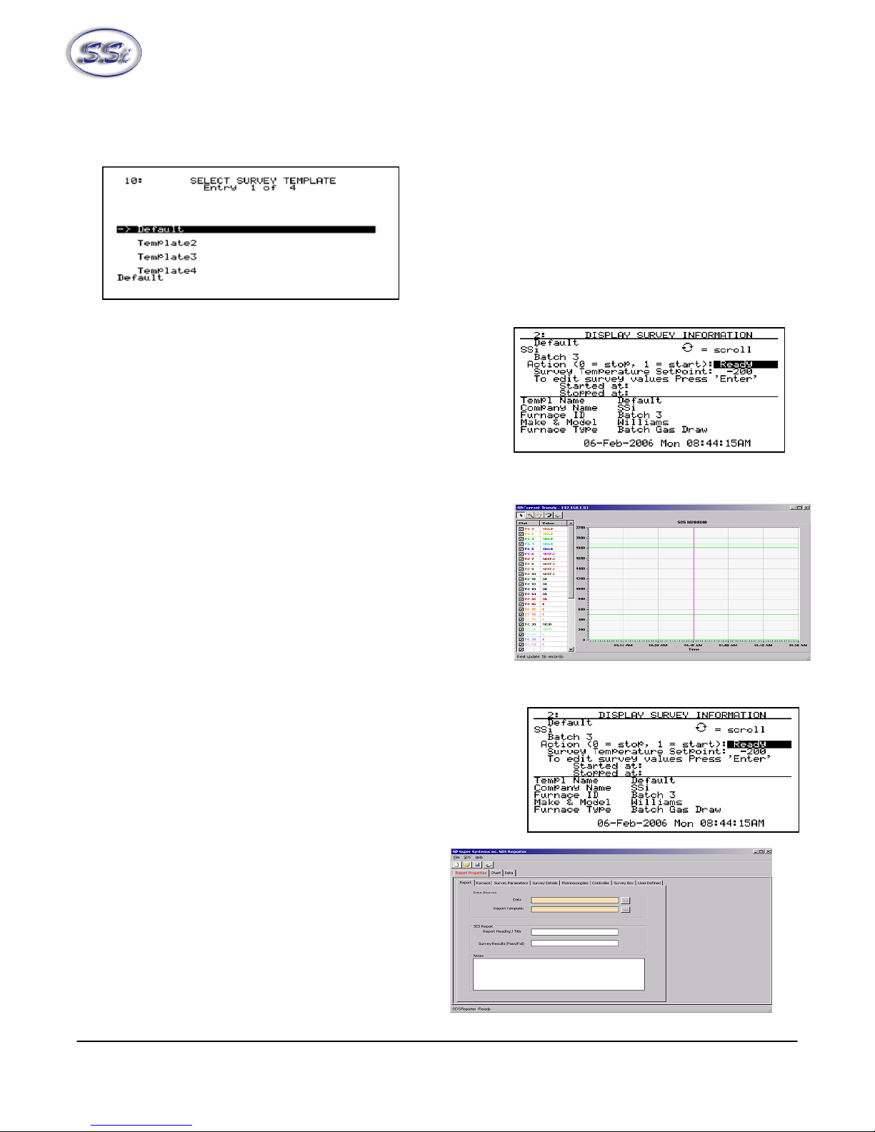
Survey Templates
The data logger will default to the last survey template used. To modify the template being used, the
operator can go to the
Select Survey Template
menu
option. This data will be carried over for the reporting
process to make the reporting quick and easy. On the
Survey Template screen there are parameters that can
be modified for a specific survey such as setpoint.
After setting the required parameters, the start survey
process can be selected. This will timestamp the
selection and the data logger will log all channels that have been selected for logging.
The operator may receive deviation alarms depending on the
current input and setpoint as well as the alarm settings. The
alarm will notify the operator when an input is outside the
plus/minus tolerance for the setpoint. The alarm information
will display on the data logger and show the number of
channels above tolerance and below the tolerance. The
survey continues to run, it is simply providing the operator
with the information on the display.
The operator can view the input channel data on a number of
different screens. The
overview display
will display all
channels on the device but by using the circular arrow key,
, the operator views the
overview display
with only the
“selected” input channels. By pressing the circular arrow key
again, the operator will get the
Quick Chart View
screen
displaying trend data for a specific channel.
At anytime, the operator can view the data in real-time from
the computer using the SDS Recorder software. The real-time
data option when selected displays the data every 10 seconds. The system will update 10-second
intervals every minute. Follow instructions for connecting the datalogger to the PC.
The survey can be stopped from the
Display Survey
Information
screen. On the Action option, entering a “0” and pressing the
Enter key will stop the survey.
After stopping the survey, other surveys can be taken by
repeating the above steps. At anytime, all survey data can be
downloaded to the PC using the Download Surveys And Data
option on SDS Recorder. Follow instructions for
connecting the datalogger to the PC.
Once the data has been downloaded, it is available
for reporting. By clicking on the file open menu
option, the operator will be given the Report dialog
to generate a survey report. Reports use logged
data and the user specified interval in the report.
The report template selected will form the final
report view with all the template data, survey data
and additional report parameters that are entered.

Super Systems Inc. Page 9 SDS Data Logger Manual #4565 Rev D
The report templates are user defined and should be configured to meet your needs. All reports can be
saved and displayed at a later date.
Super Systems Inc. Page 10 SDS Data Logger Manual #4565 Rev D
I
In
ns
st
ta
al
ll
la
at
ti
io
on
n
Installing the SDS Software
Note – The person installing the SDS Software must have administrative rights on the
computer(s) where the installation is taking place for the installation to be successful.
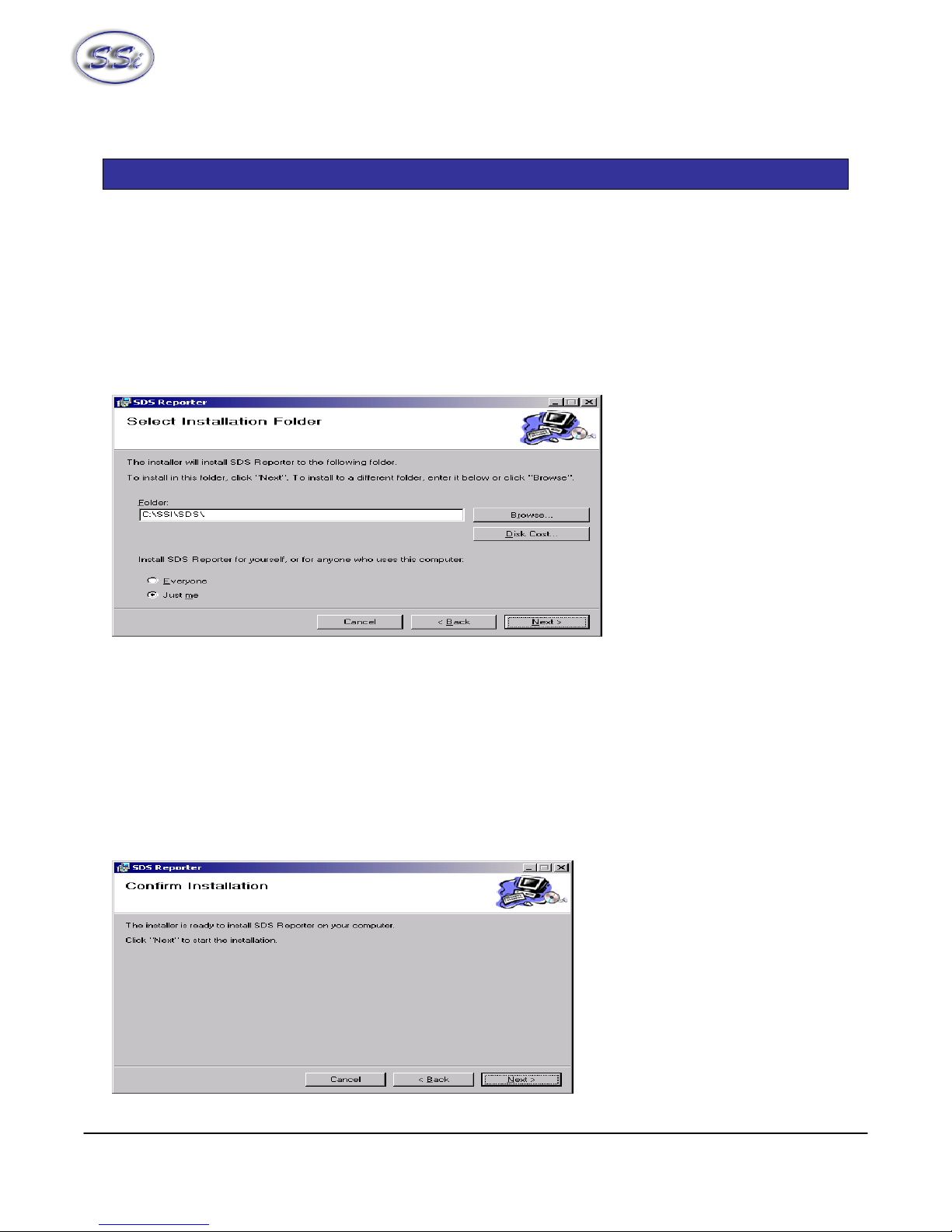
Double-click on the setup file, SDSSetup.msi to start the auto-installation. If there is no version of the
SDS Reporter running on the computer, the installation will prompt the user for the download location
(figure 1.1).
Figure 1.1 SDS Reporter setup screen
The default location is “C:\SSI\SDS”. Click on the “Browse” button to select an alternate location.
Clicking on the “Disk Cost…” button will display the available computer drives onto which the SDS
Reporter can be downloaded, as well as the total space, available space, and required space for each
drive. Selecting the “Everyone” option will install the SDS Reporter for all users on the computer, while
selecting the “Just me” option will only install the SDSReporter for the current user. Clicking on the
“Cancel” button will prompt the user to confirm exiting the setup without continuing. Clicking on the “<
Back” button will display the previous screen, which is the introduction screen for the installer. Clicking
the “Next >” button will continue with the installation process (figure 1.2).
Super Systems Inc. Page 11 SDS Data Logger Manual #4565 Rev D
Figure 1.2 Installation ready screen
Clicking on the “Cancel” button will prompt the user to confirm exiting the setup without continuing.
Clicking on the “< Back” button will display the previous page, which is the installation setup page (figure
1.1). Clicking on the “Next >” button will install the software to the specified location. Once the
software has been installed, the installer can be closed. The SDS Reporter software will now be ready to
use.
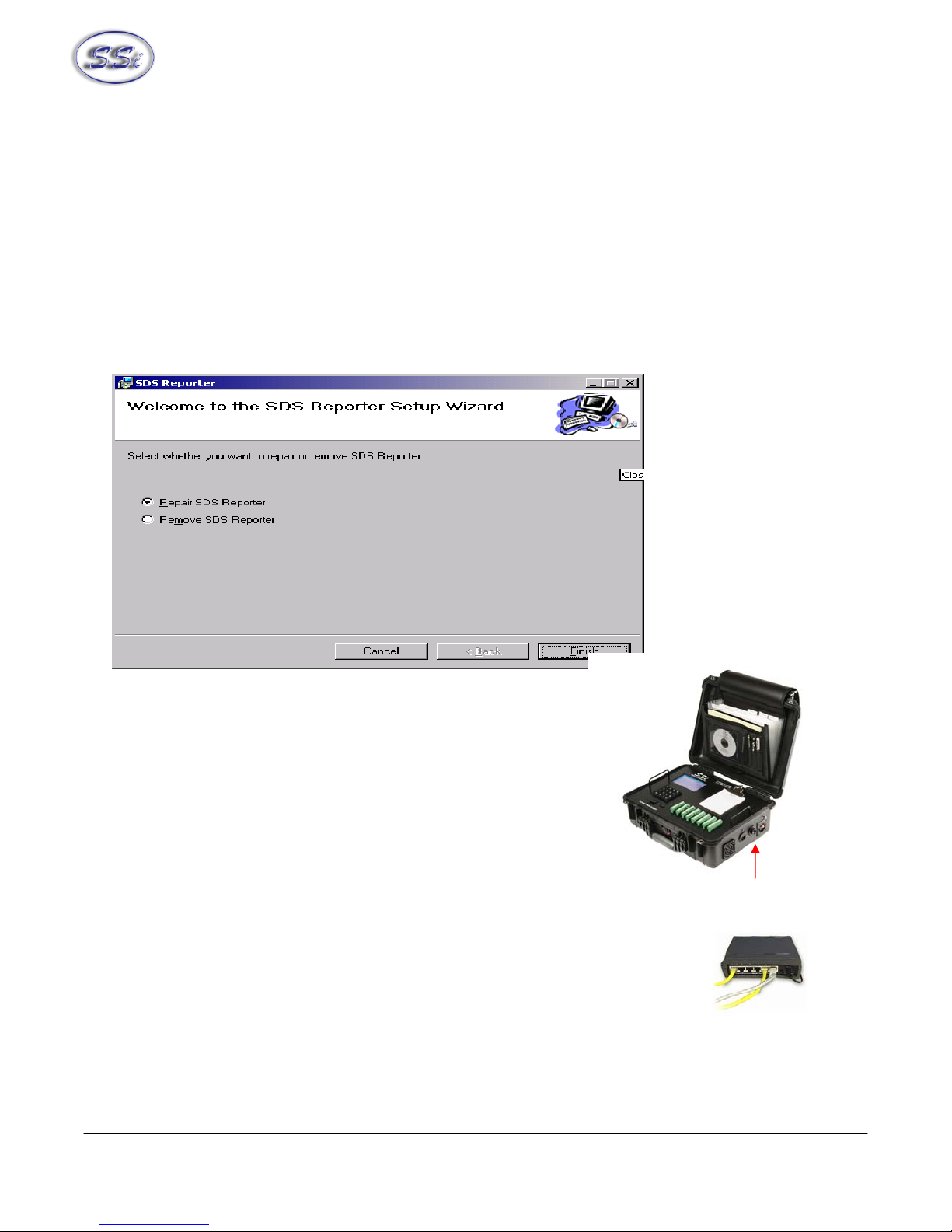
If there is a version of the SDS Reporter already installed on the computer, the installer will either re-
install the software (Repair SDS Reporter option) or remove the software from the computer (Remove
SDS Reporter option) (figure 1.3). Clicking on the “Finish” button will proceed with the selected action.
Note: the installer does not remove any subfolders in the main SDS folder. These files will have to be
manually removed.
Figure 1.3 Repair/Remove SDS Reporter screen
Connecting The SDS Data Logger To A Network
Every SDS Data Logger shipped includes an Ethernet crossover
cable that will connect the data logger to a network. Once the
data logger is connected to a network, the SDS Reporter software
will be able to find it during any searches.
Connecting the data logger to your network or directly to
a PC is accomplished using the Ethernet port on your data logger.
If you are connecting the data logger to your network, you will need an Ethernet
cable (the cable provided is a crossover cable for direct connections to a PC). The
cable is plugged into the data logger Ethernet plug and then other end should be
plugged into a network hub. If the IP Address of the data logger needs to be
changed, this can be done on the data logger through the Set IP Address menu
option.
If you are not putting the data logger on the network, you should use the Ethernet crossover cable that
has been provided with the device. Ethernet crossover cables are most often used when connecting two
Ethernet Port

Super Systems Inc. Page 12 SDS Data Logger Manual #4565 Rev D
Ethernet computers without a hub. An Ethernet crossover cable has it's send and receive wires crossed.
When using a hub or switch, this is automatically done for you.
With a crossover cable, you are forming a network between the computer that you are directly plugged
into and the data logger. There will be some network settings on the computer that you will have to
configure for the 2 devices to communicate. The data logger will have the network setting already setup
with the following IP address – 192.168.1.215. This can be modified through the Set IP Address screen
on the data logger.
Network settings can be found through the
Control Panel
in Microsoft Windows. By selecting
Network
Setting
, the operator will be
given a list of the current
available connection types.
Using the crossover cable will
require the Local Area
Connection as seen in the below
diagram to be modified. The
Properties can be changed by
highlighting the connection and
using the right mouse button to
click and select the Properties tab
or by highlighting the connection and clicking on Change setting of this
connection.
Once the Local Area Connection Properties screen is displayed, the
Internet Protocol (TCP/IP) tab should be highlighted. Click the
Properties button to display Internet Protocol
(TCP/IP) Properties.
On the Internet Protocol (TCP/IP) Properties tab,
you will need to select the option for Use The
Following IP Address. Enter in the following data
on these fields.
IP Address: 192.168.1.209
Subnet Mask: 255.255.255.0
Default Gateway: 192.168.1.1
To change the network settings on your computer you may need addition information so please refer to
the computer manual.

Super Systems Inc. Page 13 SDS Data Logger Manual #4565 Rev D
S
SD
DS
S
8
80
02
20
0/
/8
80
04
40
0
D
Da
at
ta
a
L
Lo
og
gg
ge
er
r
Menu List
The menu list shows the available pages displayed six at a time. To access the list, press the Esc key.
Depending upon where you are starting from, it may require pressing this button more than once. The
up (Ï) and down (Ð) arrows are used to scroll through the selections, which are repeated below. To go
to a specific page, either type in the page number and press Enter, or use the arrow keys to highlight
the selection and press Enter.
Operator Level – No Pass Code Required
1. Overview Display
2. Display Input Settings
3. Display Input Settings
4. Display Input Offsets
5. Display Logged Data
6. Help
7. Select Input Channels
8. Modify Input Settings
9. Modify Input Offsets
10. Select Survey Template
11. Battery Status
12. About/Sign-On
13. Revision Display
14. Set Display Values
15. Language/Lengua
16. Quick Chart
17. Overview Display Selected
18. Quick Chart Setup
19. Modify Survey Information
Supervisor Level – Level 1 Pass Code Required

Super Systems Inc. Page 14 SDS Data Logger Manual #4565 Rev D
20. Set the Date and Time
21. Port Setup
22. Input Calibration
23. Cold Junction Trim
24. System Setup
Configuration Level – Level 2 Pass Code Required
25. Set Pass Codes
26. Set IP Address
Menu Pages 27, 28 and 29 are reserved for future use and do not exist at this time. To minimize the
possibility of unintended modifications to the instrument, certain menu pages will require the entry of a
pass code to access them. Pages 1 through 18 are Operator level screens that do not require any
security codes. Pages 20 through 24 are Supervisor screens requiring a Level 1 pass code (default = 1).
Pages 25 and 26 are Configuration screens requiring a Level 2 pass code (default = 2). At the bottom of
the menu screen is a status bar, which tells the current date and time. The status bar also displays the
internal temperature (IT) of the instrument. This internal temperature should never exceed 50.
Note About Menu Numbers
Each menu screen has a unique number that is displayed in the upper left-hand corner of the screen.
This number is shown for reference. If you know the menu number of the screen that you would like to
go to, the screen number can be typed and the enter key pushed to access that particular screen directly
from the Main Menu list or the Overview Display screen.

Super Systems Inc. Page 15 SDS Data Logger Manual #4565 Rev D
Date and Time Quick Reference Chart
Month Code Day Code Hour Code Hour Code
January 1 Sunday 0 12 am 0 12 pm 12
February 2 Monday 1 1 1 1 13
March 3 Tuesday 2 2 2 2 14
April 4 Wednesday 3 3 3 3 15
May 5 Thursday 4 4 4 4 16
June 6 Friday 5 5 5 5 17
July 7 Saturday 6 6 6 6 18
August 8 7 7 7 19
September 9 8 8 8 20
October 10 9 9 9 21
November 11 10 10 10 22
December 12 11 11 11 23
Super Systems Inc. Page 16 SDS Data Logger Manual #4565 Rev D
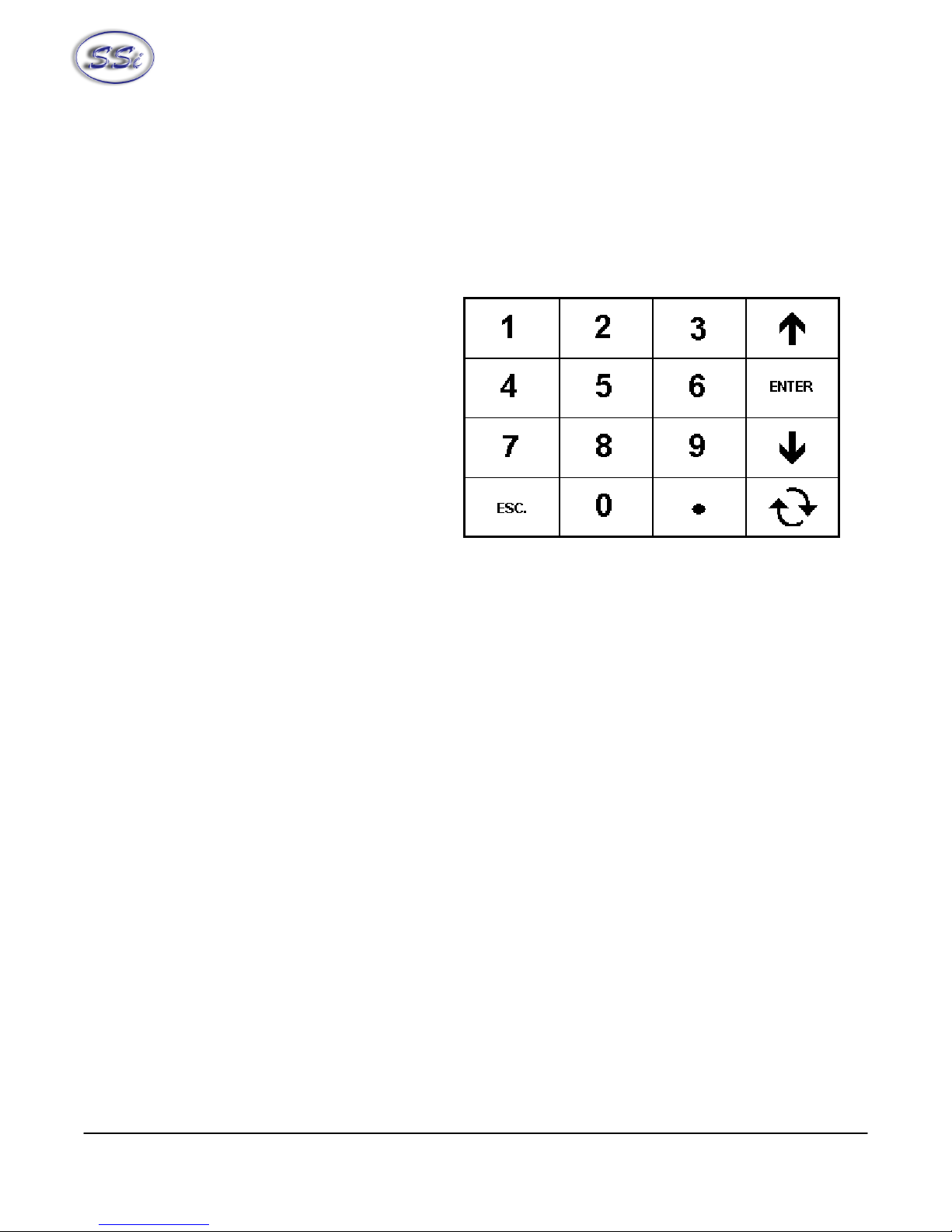
Keypad Assignments
All of the functions of the SDS Data Logger are controlled from the keypad. The functions of each button
are as follows:
0 – 9 are used to enter numeric data that
can vary with each page
“.” Is used to enter a decimal point where
necessary for data entry
Enter is used when entering numeric data
from the keypad or initiating automatic
functions
Ïand Ðare used to navigate through the
menu options or scroll through data on a
specific page
ESC is the escape key. This clears any
entered text, and if continuously pressed,
toggles between the main page and the
menu list
The circular arrow key, , is used to scroll through data on various pages and to change the sign, +/-,
of values on some pages
Super Systems Inc. Page 17 SDS Data Logger Manual #4565 Rev D
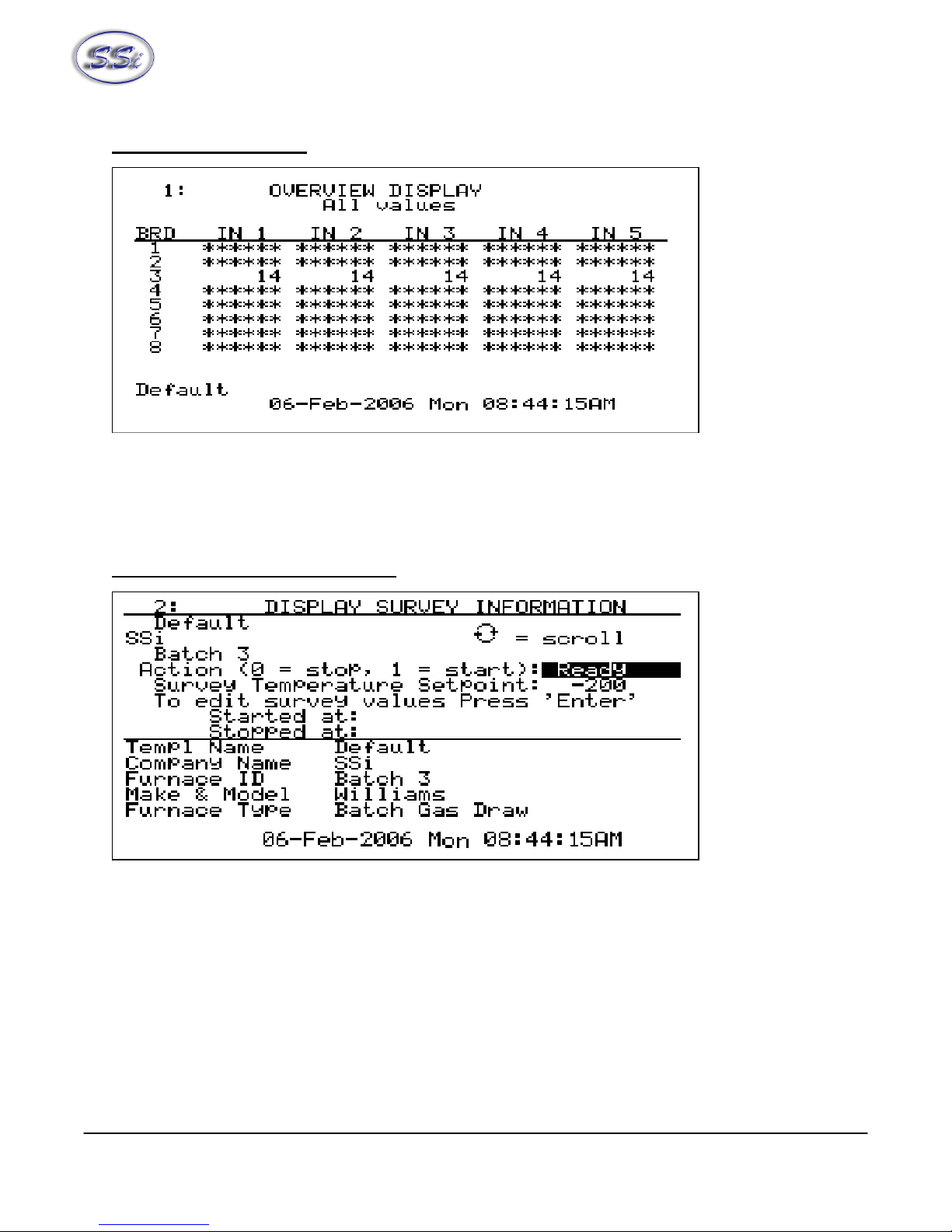
1. Overview Display
The Overview Display shows the current readings of the five thermocouples on all four or eight boards,
depending on the number of channels. Pressing the circular arrow key will display the
Quick Chart screen
(menu option 16). Pressing the up or down arrow keys will display the
Modify Input Offsets
screen
(menu option 9). Pressing any of the number keys (1-9) will display the corresponding menu option.
2. Display Survey Information
The Display Survey Information shows the survey information on the top half of the screen. Included is
the Template name, Company name, Furnace ID, Action (start or stop the survey), Survey Temperature
Setpoint, A field to edit the survey values, The Date/Time the survey was started and the Date/Time the
survey was stopped. Pressing the up or down arrow keys will scroll through the Action, Setpoint and Edit
survey fields. Pressing Enter on the line “To edit survey values Press ’Enter’” will display the
Modify
Survey Information
screen (menu option 19), which allows the user to modify some of the information
used in the survey. Currently, the only information that can be modified are the Setpoint, TC units, and
TC spool correction.
To start the survey, highlight the Action field, enter a 1and then press Enter. Once a survey has been
started, “Testing” will appear in the highlighted area and the start Date/Time will be filled in the “Started
at” field.

Super Systems Inc. Page 18 SDS Data Logger Manual #4565 Rev D
To stop a survey, highlight the Action field, enter a 0and then press Enter. Once the survey has
finished, “Finished” will appear in the highlighted area and the stop Date/Time will be filled in the
“Stopped at” field.
To change the Setpoint, highlight the Setpoint field, enter in the new Setpoint and press Enter. Pressing
the circular arrow key while the setpoint field is highlighted will change the sign of the value entered.
The bottom half of the screen contains the full template data displayed five lines at a time: Template
Name, Company Name, Furnace ID, Furnace Make/Model, Furnace Type, Furnace Use, Furnace
Dimensions, Temperature Range, Date, Setpoint, Number of TCs, TC Type, TC Spool SN, TC Cal, TC Cal
Date, TC Spool Correction, SDS Calibrated By, SDS Cal Date, Duration, Operator, Interval, Specification,
TC Units, Simulated Load, Tolerance, Next Survey, Cont MFG, Cont Model, Cycle Time, Dead Band,
Output Limit, Prop Band, Rate, Reset, TC Gauge, and Notes. Pressing the circular arrow key will scroll
down through the template data, one line at a time. When the end of the template is reached, the scroll
will start over at the beginning of the template.
3. Display Input Settings
The Display Input Settings shows the input settings for all five thermocouples on all four/eight boards.
Pressing any of the number keys (1-9) will display the corresponding menu option. Pressing the down
arrow key will display the
Modify Input Settings
screen (menu option 8).

Super Systems Inc. Page 19 SDS Data Logger Manual #4565 Rev D
4. Display Input Offsets
The Display Input Offsets screen displays the offsets for all five thermocouples on all four /eight boards,
depending on the SDS type. Pressing the down arrow key will display the
Modify Input Offsets
screen
(menu option 9). Pressing any of the number keys (1-9) will display the corresponding menu option.
5. Display Logged Data
The Display Logged Data shows the logged data from a specific date, with the default setting being the
current hour of the current date. Pressing the down arrow key will allow the user to change the Year,
Month, Day, and Hour. To change the Year, highlight the area and enter any four-digit year between
1980 and 2179. To change the Month, enter a number corresponding to the appropriate month – i.e. 1
for January, 12 for December. To change the Day, enter a number between 1and 31. To change the
Hour, enter a number between 0and 23 corresponding to the appropriate hour – i.e. 0for 12am and 23
for 11pm. Hours are based on the 24-hour clock. For a detailed reference for all of the codes, see the
Date and Time Quick Reference Chart
section (Page 19). Pressing Enter on the line that says “To
Display Press ’Enter’ here” will display the logged data.

Super Systems Inc. Page 20 SDS Data Logger Manual #4565 Rev D
The first screen will display the first five inputs and the first ten minutes of data. Pressing the circular
arrow button will allow the user to scroll through the inputs, five inputs at a time. Pressing the down
arrow button will show the next ten minutes of logged data. Pressing the up arrow will show the
previous ten minutes of logged data. Pressing the ESC key will display the
Display Logged Data
Screen.
6. Help
The Help page can be used as a reference to briefly describe the functions of the various buttons on the
keypad. This manual is a better resource, however if it is not available this screen will be able to offer
information that will help in navigating through the screens on the SDS. To scroll through the screen
pages, press the down arrow key to scroll down and the up arrow key to scroll up.
7. Select Input Channels
The Select Input Channels page allows the user to manually turn a thermocouple input “on” (“Yes”) or
“off” (“No”). The thermocouples are displayed from one to twenty / forty. Use the up or down arrow
keys to select a specific thermocouple. Enter a 1and then press Enter to turn the thermocouple on, or
enter a 0and press Enter to turn the thermocouple off. Pressing Enter without entering a 1or a 0 will
This manual suits for next models
3
Table of contents


