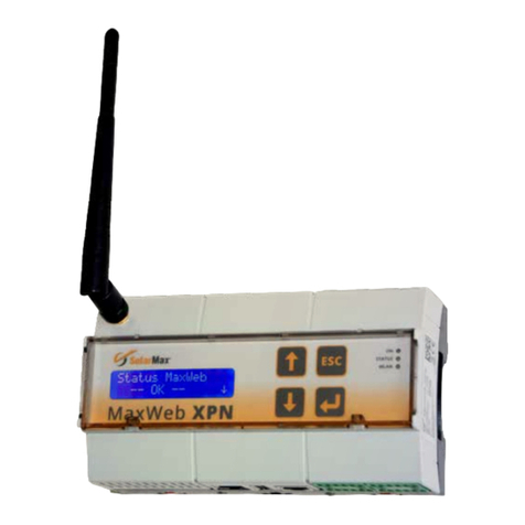
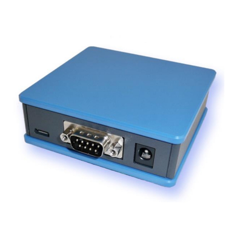
SolarMax MaxWeb xp User manual

Installation instructions
MaxWeb xp

2
Contents
1 About this installation manual � � � � � � � � � � � � � � � � � � � � � � � � � � � � � � � � � � � � � � 3
1.1 Scope. . . . . . . . . . . . . . . . . . . . . . . . . . . . . . . . . . . . . . . . . . . . . . . . . . . . . . 3
1.2 Target group. . . . . . . . . . . . . . . . . . . . . . . . . . . . . . . . . . . . . . . . . . . . . . . . . 3
1.3 Where to keep this manual . . . . . . . . . . . . . . . . . . . . . . . . . . . . . . . . . . . . . . 3
1.4 Symbols used. . . . . . . . . . . . . . . . . . . . . . . . . . . . . . . . . . . . . . . . . . . . . . . . 3
2 Safety � � � � � � � � � � � � � � � � � � � � � � � � � � � � � � � � � � � � � � � � � � � � � � � � � � � � � � � � � � 4
2.1 Appropriate use . . . . . . . . . . . . . . . . . . . . . . . . . . . . . . . . . . . . . . . . . . . . . . 4
2.2 Safety instructions . . . . . . . . . . . . . . . . . . . . . . . . . . . . . . . . . . . . . . . . . . . . 4
3 Description � � � � � � � � � � � � � � � � � � � � � � � � � � � � � � � � � � � � � � � � � � � � � � � � � � � � � � 5
3.1 Connections . . . . . . . . . . . . . . . . . . . . . . . . . . . . . . . . . . . . . . . . . . . . . . . . . 5
3.2 Displays . . . . . . . . . . . . . . . . . . . . . . . . . . . . . . . . . . . . . . . . . . . . . . . . . . . . 5
4 Installation � � � � � � � � � � � � � � � � � � � � � � � � � � � � � � � � � � � � � � � � � � � � � � � � � � � � � � 6
4.1 Transporting and storing data logger . . . . . . . . . . . . . . . . . . . . . . . . . . . . . . 6
4.2 Scope of delivery . . . . . . . . . . . . . . . . . . . . . . . . . . . . . . . . . . . . . . . . . . . . . 6
4.3 Siting . . . . . . . . . . . . . . . . . . . . . . . . . . . . . . . . . . . . . . . . . . . . . . . . . . . . . . 6
4.4 Device installation . . . . . . . . . . . . . . . . . . . . . . . . . . . . . . . . . . . . . . . . . . . . 7
5 Installation of the MaxComm network � � � � � � � � � � � � � � � � � � � � � � � � � � � � � � � � 7
5.1 Connection options. . . . . . . . . . . . . . . . . . . . . . . . . . . . . . . . . . . . . . . . . . . . 7
5.2 Wiring. . . . . . . . . . . . . . . . . . . . . . . . . . . . . . . . . . . . . . . . . . . . . . . . . . . . . . 8
5.3 Addressing . . . . . . . . . . . . . . . . . . . . . . . . . . . . . . . . . . . . . . . . . . . . . . . . . . 9
5.4 Ethernet connection . . . . . . . . . . . . . . . . . . . . . . . . . . . . . . . . . . . . . . . . . . 10
5.5 Power supply . . . . . . . . . . . . . . . . . . . . . . . . . . . . . . . . . . . . . . . . . . . . . . . .11
5.6 Changes in the MaxComm network . . . . . . . . . . . . . . . . . . . . . . . . . . . . . . .11
6 Conguration of MaxWeb xp � � � � � � � � � � � � � � � � � � � � � � � � � � � � � � � � � � � � � � � �12
6.1 Switching on and off . . . . . . . . . . . . . . . . . . . . . . . . . . . . . . . . . . . . . . . . . .12
6.2 General. . . . . . . . . . . . . . . . . . . . . . . . . . . . . . . . . . . . . . . . . . . . . . . . . . . . .12
6.2.1 Connection cable. . . . . . . . . . . . . . . . . . . . . . . . . . . . . . . . . . . . . . .12
6.2.2 IP Address. . . . . . . . . . . . . . . . . . . . . . . . . . . . . . . . . . . . . . . . . . . .12
6.2.3 Modifying your network settings . . . . . . . . . . . . . . . . . . . . . . . . . . .13
6.3 MaxWeb xp Ethernet. . . . . . . . . . . . . . . . . . . . . . . . . . . . . . . . . . . . . . . . . . .14
6.4 MaxWeb xp GPRS . . . . . . . . . . . . . . . . . . . . . . . . . . . . . . . . . . . . . . . . . . . . .14
6.4.1 Recommendations for the SIM card . . . . . . . . . . . . . . . . . . . . . . . .14
6.4.2 Installation instructions for the MaxWeb xp GPRS . . . . . . . . . . . . . .15
6.4.3 GPRS conguration . . . . . . . . . . . . . . . . . . . . . . . . . . . . . . . . . . . . .15
6.5 Conguration using MaxWeb Wizard . . . . . . . . . . . . . . . . . . . . . . . . . . . . . .18
6.5.1 Select language. . . . . . . . . . . . . . . . . . . . . . . . . . . . . . . . . . . . . . . .18

en
3
6.5.2 LAN settings . . . . . . . . . . . . . . . . . . . . . . . . . . . . . . . . . . . . . . . . . .18
6.5.3 Connection test . . . . . . . . . . . . . . . . . . . . . . . . . . . . . . . . . . . . . . . .19
6.5.4 Contract data . . . . . . . . . . . . . . . . . . . . . . . . . . . . . . . . . . . . . . . . 21
6.5.5 Plant settings . . . . . . . . . . . . . . . . . . . . . . . . . . . . . . . . . . . . . . . . 22
6.5.6 Device communications settings. . . . . . . . . . . . . . . . . . . . . . . . . . 22
6.5.7 Find devices . . . . . . . . . . . . . . . . . . . . . . . . . . . . . . . . . . . . . . . . . 23
6.5.8 Device settings . . . . . . . . . . . . . . . . . . . . . . . . . . . . . . . . . . . . . . . 24
6.5.9 Energy values . . . . . . . . . . . . . . . . . . . . . . . . . . . . . . . . . . . . . . . . 25
6.5.10 Time values. . . . . . . . . . . . . . . . . . . . . . . . . . . . . . . . . . . . . . . . . . 26
6.5.11 Alarming . . . . . . . . . . . . . . . . . . . . . . . . . . . . . . . . . . . . . . . . . . . . 28
6.5.12 Energy comparison . . . . . . . . . . . . . . . . . . . . . . . . . . . . . . . . . . . . 29
6.5.13 Date/time settings. . . . . . . . . . . . . . . . . . . . . . . . . . . . . . . . . . . . . 30
6.5.14 Finishing the MaxWeb Wizard . . . . . . . . . . . . . . . . . . . . . . . . . . . 30
6.6 MaxWeb Portal registration . . . . . . . . . . . . . . . . . . . . . . . . . . . . . . . . . . . . 31
6.7 Re-establishing the wiring for MaxWeb xp GPRS . . . . . . . . . . . . . . . . . . . . 31
6.8 External displays . . . . . . . . . . . . . . . . . . . . . . . . . . . . . . . . . . . . . . . . . . . . 31
6.8.1 Activating MaxDisplay. . . . . . . . . . . . . . . . . . . . . . . . . . . . . . . . . . 31
6.8.2 Connecting the display . . . . . . . . . . . . . . . . . . . . . . . . . . . . . . . . . 31
7 Access to the PV plant � � � � � � � � � � � � � � � � � � � � � � � � � � � � � � � � � � � � � � � � � � � � 32
7.1 Opening the MaxWeb Portal . . . . . . . . . . . . . . . . . . . . . . . . . . . . . . . . . . . . 32
7.2 Opening the MaxWebxp user interface . . . . . . . . . . . . . . . . . . . . . . . . . . . 32
8 Expansion Port � � � � � � � � � � � � � � � � � � � � � � � � � � � � � � � � � � � � � � � � � � � � � � � � � � 34
8.1 Connection options. . . . . . . . . . . . . . . . . . . . . . . . . . . . . . . . . . . . . . . . . . . 34
8.2 Irradiance and temperature sensor. . . . . . . . . . . . . . . . . . . . . . . . . . . . . . . 34
8.3 Conguration . . . . . . . . . . . . . . . . . . . . . . . . . . . . . . . . . . . . . . . . . . . . . . . 36
8.4 Inputs for external alarm sensors . . . . . . . . . . . . . . . . . . . . . . . . . . . . . . . . 36
8.5 Terminal assignment . . . . . . . . . . . . . . . . . . . . . . . . . . . . . . . . . . . . . . . . . 37
9 Troubleshooting � � � � � � � � � � � � � � � � � � � � � � � � � � � � � � � � � � � � � � � � � � � � � � � � � 38
10 Technical data � � � � � � � � � � � � � � � � � � � � � � � � � � � � � � � � � � � � � � � � � � � � � � � � � � 38
11 Disposal� � � � � � � � � � � � � � � � � � � � � � � � � � � � � � � � � � � � � � � � � � � � � � � � � � � � � � � � 39
12 Warranty � � � � � � � � � � � � � � � � � � � � � � � � � � � � � � � � � � � � � � � � � � � � � � � � � � � � � � � 39

4
1 About this installation manual
This installation guide describes the installation, the startup and the functions of the Max-
Comm accessory component MaxWeb xp. Sputnik Engineering AG declines any liability in
the event of non-observance of the installation instructions.
1�1 Scope
This installation manual applies to MaxWeb xp data loggers:
Device type Order number
MaxWeb xp Ethernet 1310-2
MaxWeb xp GPRS 1310-4
1�2 Target group
The installation of the MaxWeb xp may only be carried out by trained, skilled electri-
cians (e.g. electricians, electric systems technicians, electrical mechanics, industrial
electronics technicians).
1�3 Where to keep this manual
The system operator must ensure that this instruction manual is available to those
responsible for the power plant at all times. If this original manual is lost, an up-to-date
version can be downloaded from our website at all times (www.solarmax.com).
1�4 Symbols used
The following safety instructions and general information are used within this instruction
manual.
DANGER!
Non-observance of these safety instructions may immediately cause serious
injuries or death.
WARNING!
Non-observance of these safety instructions may cause serious injuries.
ATTENTION!
Non-observance of these safety instructions may cause material damage.
Note
Notes contain extended information or facilitate the data logger operation.

en
5
2 Safety
2�1 Appropriate use
The web-based MaxWeb xp data logger is solely for the logging of device and plant data
within a MaxComm communications network. MaxWeb xp provides the following basic
functions:
Internet-capable data logger for system communication via standard Internet
browser
Automatic data transfer to the MaxWeb Portal and three further e-mail recipients as
XML le
Permanent system monitoring
Automatic alarms via e-mail or SMS to up to three recipients
Up to 75 devices can be connected via RS485 interface
Communication via GPRS or Ethernet
Control of large-format displays
2�2 Safety instructions
DANGER!
Fatal electric shock hazard!
Never open the plug-in mains unit. Components within the plug-in mains
unit are charged with a high voltage.
ATTENTION!
Risk of damage to the device!
Only SolarMax devices with RS485 type interfaces may be connected to
RS485 sockets. The interface carries active signals.

6
3 Description
3�1 Connections
RS485 RS485
Modem
ISDN Ethernet +15VDC
Expansion Port
GSM
Port Purpose
Expansion Port Connection for irradiation and temperature sensors, for external alarm
systems and a wireless reciever for the optional MaxRemote. Active
signals! (see Section 8).
GSM Screw terminal for connecting the GSM aerial (GPRS version only).
Ethernet RJ45 socket for Ethernet connection cable.
Modem / ISDN RJ45 socket for modem connection cable and for the conguration of
the GPRS modem.
RS485 RJ45 sockets for connecting the MaxComm network cable. Active
signals!
+15 VDC Jack socket for connecting the 15 VDC plug-in power supply unit.
3�2 Displays
The ve LEDs at the top of the casing indicate the operational status.
MaxWeb xp Ethernet
RI CD DATA STATUS OH
no
function
On: electrical connection
to the network is active.
Off: no connection.
Flashes during data
reception from the
devices.
Lights up when
MaxWeb xp is running.
no
function

en
7
MaxWeb xp GPRS
RI CD DATA STATUS OH
no
function
On: Lights up if
the Ethernet/GPRS
bridge is inserted.
Flashes during
data reception
from the devices.
Lights up when
MaxWeb xp is
running.
On: the device is registered
in the GSM network and
connected to the Internet.
Off: the device is not regis-
tered in the GSM network.
Flashing: initialisation
phase.
4 Installation
4�1 Transporting and storing data logger
Ensure that the ambient conditions during transportation and storage are within the spec-
ied limits (see Section 10).
4�2 Scope of delivery
Please check that the following parts are included:
Quantity Description
1MaxWeb xp
1Installation manual
1 Plug-in power supply unit 230 VAC / 15 VDC
1 Assembly components for wall and top hat rail mounting
1 Ethernet connection cable (patch cable) for connection to a LAN network, DSL
router or switch/hub (grey)
1 Crossover Ethernet connection cable for connection to a PC (red)
For the MaxWeb xp GPRS version additionally:
Quantity Description
1 GSM aerial with connection cable
1 Crossover Ethernet connection cable (short, red)
4�3 Siting
Please note the following when siting your MaxWebxp:
MaxWeb xp meets the requirements of protection class IP20 and is therefore only
suitable for installation in dry, clean spaces. For outdoor installation or operation

8
under adverse conditions the device must be mounted in an additional casing that
meets the requirements of the required protection class.
The ambient temperature must be between –20 °C and +40 °C.
To connect the plug-in power supply a 230 V power socket must be within reach of
the connection cable.
For the GPRS version, the GSM signal of the respective mobile communications pro-
vider must be adequately strong. The GSM must be installed in a suitable location.
4�4 Device installation
Wall
Attach the two grey PVC parts to the back of the device using the enclosed screws. The
device can now be simply installed at the selected location.
Top-hat rail
Attach the two grey metal parts to the back of the device using the enclosed screws. The
device can now be simply hooked into a 35mm top-hat rail.
5 Installation of the MaxComm
network
5�1 Connection options
Up to 75 devices with a MaxComm interface can be connected to your MaxWeb xp data
logger.
Device Purpose
SolarMax inverters All SolarMax inverters from the E and C series
MaxMeteo Module for connecting a temperature and irradiance sensor
MaxCount Module for connecting pulse counters with S0 interface (utility
companies)
MaxConnect plus Generator connection box with string current monitoring
MaxDisplay 1.0 / 2.0 LCD or LED large displays with MaxComm interface / Large
displays with a MaxComm interface are offered by several display
manufacturers

en
9
5�2 Wiring
Use commercially available RJ45 network cables, also referred to as RJ45 patch cables,
for wiring the MaxComm network. These cables are available in different lengths from
IT retailers. Alternatively you may assemble the cables yourself using suitable tools. We
recommend using single-screened category 5 cables (CAT 5e).
DANGER!
Fatal electric shock hazard!
For the connection to a network it may be necessary to open the inverter.
Components within the inverter are charged with a high voltage.
Never open an inverter while it is in operation.
Open the inverters as described in the device documentation or installa-
tion manual.
The string inverters of the S and MT series do not have to be opened for
the connection to a network.
The two gures below show the recommended connection options for MaxWeb GPRS.
Other topologies are not recommended owing to the high data volumes and corresponding
high connection costs.
Connection option with bridge between the “Modem ISDN” and “Ethernet” connec-
tions (the bridge is included in the delivery package):
RS485RS485
SM C
RS485/LANRS485
SM S/MT/TS/TS-SV
RS485
RS485
Ethernet
Modem
ISDN
MaxWeb xp GPRS
RS485 RS485
WWW
GPRS

10
Connection option with external modem:
RS485RS485
SM C
RS485/LANRS485
SM S/MT/TS/TS-SV
RS485
RS485
Ethernet
Modem
ISDN
MaxWeb xp GPRS
RS485 RS485
Modem
WWW
GPRS
Note
Special RJ45 connector kits with IP54 protection for C and S series string
inverters are available from your SolarMax distributor. These connectors
must be used unless the inverters are installed in a dry, clean
environment.
The maximum cable length for MaxComm networks is 300 metres.
Should you wish to install a larger network, please contact the SolarMax
service centre.
5�3 Addressing
For MaxWeb xp to be able to detect connected devices, you must assign an unambiguous
device address to every device. Please note that each device address must be used once
only. You will nd instructions for setting the address in the product description of the
corresponding device.

en
11
5�4 Ethernet connection
All inverters and devices with an Ethernet interface can be operated within a LAN network
together with MaxWeb xp.
The inverters connected to MaxWeb xp by means of the Ethernet interface assume the
gateway function for the other devices. Behind the gateway inverters the MaxComm net-
work consists of RS485 connections.
The following gure shows the recommended connection option with MaxWeb xp
Ethernet:
RS485/LANRS485
SM S/MT/TS/TS-SV
RS485
RS485
Ethernet
Modem
ISDN
MaxWeb xp Ethernet
Ethernet EthernetRS485 (+15 Vdc)Display
Ethernet-Switch
LAN
RS485RS485
SM C
Please observe the following items, if you are using this mode of operation:
MaxWeb xp does not allow for simultaneous connection of Ethernet and RS485
connections.
You must congure the gateway inverters for the Ethernet connection. You can nd
information on the aforementioned in the device documentations.
The TCP port must be identical for all gateway inverters.
Each device within the MaxComm network must be equipped with an unambiguous
device address (the gateway inverters as well).
The MaxWeb xp connection option must be set to the Ethernet interface.
The automatic DHCP network connection is not supported by MaxWeb xp. For this
reason, the devices in the MaxComm network need a static IP address.
Depending on the devices used and the design of the MaxComm network, additional
network infeeds are required.

12
Note
Detailed information on the design of a MaxComm communication network
can be found in the technical details on MaxComm. This document can be
downloaded from our website (www.solarmax.com; area downloads/data
communication).
5�5 Power supply
The power supply to the data logger is supplied by the plug-in mains unit (included in the
delivery package).
WARNING!
Risk of re when unsuitable mains units are used!
For the power supply, you must use the plug-in mains unit included in the
delivery package.
Note
The power supply should be independent of the inverter AC feed cable. If
this is not the case, the MaxWeb xp will be disconnected from the power
supply when the inverters disconnect from the mains.
Use an uninterruptible 230 VAC power supply for the plug-in mains unit.
Any interruption in the mains power supply can lead to total failure of the
MaxWeb xp. In that case, the warranty becomes void and users cannot
make any claims under guarantee.
5�6 Changes in the MaxComm network
If you change the MaxComm network, e.g. by adding or replacing devices, you must rst
update the recorded data on the MaxWeb Portal.
ATTENTION!
Possible data loss!
The data logger is reset every time a device search is carried out. Update
the recorded data on the MaxWeb Portal before starting a device search.

en
13
6 Conguration of MaxWeb xp
6�1 Switching on and off
Insert the round plug connector of the plug-in mains unit into the “+15 VDC” socket of the
MaxWeb xp. Then connect the plug-in mains unit to the power supply.
As soon as the power supply is connected, MaxWeb xp starts and the status LED comes
on. After approx. 30 seconds the device is accessible via the web browser.
Always switch MaxWeb xp off via the -button! Press and hold the key until the status
LED goes out and the device switches to standby mode. The power supply can now be
removed if required.
In order to start the device from standby mode, press and hold the -button until the
status LED comes on. A restart from standby mode is possible only after 30 seconds.
6�2 General
6�2�1 Connection cable
For a connection to the LAN, the DSL router or the hub/switch use the grey cable.
For a direct connection to the Ethernet interface of your PC use the red (crossover)
cable.
6�2�2 IP Address
MaxWeb xp requires a static IP address in your network. The automatic IP address
assignment using DHCP is not supported by MaxWeb xp.
The prexed IP address of MaxWeb xp is 192.168.1.234. If the prexed address of
MaxWeb xp is outside the address range (subnetwork mask) of your network or this
address has already been assign to another device, you must temporarily modify the
network conguration of your PC (see Section 6.2.3) and change the default setting
of MaxWeb xp. Otherwise you can create a connection to MaxWeb xp without any
further settings.

14
6�2�3 Modifying your network settings
Note
Check the correctness of your entries. If the entries are faulty, there is a likeli-
hood that MaxWeb xp will no longer be accessible via the Ethernet interface
after a reboot. Just in case, write down the values you have set before you
reboot MaxWeb xp.
1. Connect MaxWeb xp directly to the Ethernet interface of your PC using the red cross-
over cable.
2. From Windows XP open the menu Control panel > Settings > Network Connections
> LAN connection.
3. Select “Internet protocol TCP/IP” and click on “Properties”.
4. Write down the existing settings.
5. Change the settings as shown in the screenshot:
Parameter Value
IP adresse 192.168.1.230
Subnetz mask 255.255.255.0
Default gateway 192.168.1.1
6. Click on “OK”.

en
15
6�3 MaxWeb xp Ethernet
For MaxWeb xp Ethernet ensure that the following router ports are open to the outside:
Port Protocol
25 (SMTP E-Mail trafc) TCP/UDP
53 (DNS) TCP/UDP
9300 (VPN) TCP/UDP
1. Switch MaxWeb xp on (see Section 6.1).
2. Open your web browser and enter the address “http://192.168.1.234”. The Login
screen of MaxWeb xp appears.
3. Log in using the user name “admin” and the password “solarmax.com”.
4. You can now continue directly with the installation Wizard (see Section 6.5).
6�4 MaxWeb xp GPRS
6�4�1 Recommendations for the SIM card
To use MaxWeb xp via GPRS you need a SIM card with GPRS data service. The services
and tariffs offered by different providers vary widely. For this reason only general instruc-
tions can be given at this point.
Required services: E-Mail, VPN, and DNS
The following ports must be activated: 25, 53, and 9300
Required protocol: TCP/UDP
Do not use pre-paid cards.
Select a provider offering good network quality at the selected location so that expen-
sive roaming fees can be avoided.
MaxWeb xp GPRS is continuously connected to the Internet. Therefore please make
sure you select a card contract that is based on data volume rather than time. Other-
wise you may incur high charges.
For smaller PV systems and daily data transfer the contract should allow for a min-
imum data volume of 300 MB per month. Select a larger data volume if you wish to
record a large quantity of data, access the installation regularly online, or transfer
data at short intervals.
Note
Data volumes quickly exceed 300 MB if MaxWeb xp must interrupt and re-
establish the VPN connection several times a day. This can happen if the
signal is too weak (see Section 6.4.2) or if other nearby GPRS devices compro-
mise the bandwidth. In situations like these you should conclude a payment
card agreement with a larger data volume.

16
Flat-rate tariffs are usually cheaper than paying for the actually transferred data.
On a pay-as-you-go contract without lump-sum tariff you should negotiate an upper
volume or fee limit with your supplier.
Please note that certain contracts are based on block rounding for the transferred
data. Select a contract with daily or session-based block rounding. Hourly block
rounding or block rounding with large data blocks (>100 kB per day) is not
advisable.
6�4�2 Installation instructions for the MaxWeb xp GPRS
The magnetic-base aerial provided is designed for application in dry rooms. It must
not be placed in metal cabinets, behind thick concrete walls, in basements or other
electromagnetically screened spaces. Installation of the aerial and operation of
MaxWeb xp GPRS near areas with strong electromagnetic radiation or areas that are
sensitive to such radiation should be avoided.
Note
Insufcient reception means greater data volumes due to malfunctioning con-
nections. You can still read the signal strength after completing the Wizard
process at “Plant data – Overview”. The value of the signal strength displayed
must be at least “16”.
For locations with weak GSM reception a rod aerial with 3 dB gain is available from
your SolarMax distributor. This aerial may be installed outdoors.
Connect the magnetic base or rod aerial to the designated “GSM” screw terminal.
Tighten the locking nut without forcing it until the limit stop is reached.
Do not insert the SIM card until you reach the step described below.
To install the SIM card, open MaxWeb xp using a small Phillips screwdriver.
Proceed with caution when installing the SIM card. Do not use force and avoid con-
tact with the electronic components. Leave the SD card in its base.
6�4�3 GPRS conguration
1. Connect the the Ethernet socket of your PC with the Modem socket of the MaxWeb xp
using the red crossover cable.
Note
To access MaxWeb xp the network connection of your PC must be appropri-
ately congured (see Section 6.2.3).
2. Switch MaxWeb xp on (see Section 6.1).
3. Enter “http://192.168.1.1” in the web browser.
4. Click OK at the login screen (no user name/password is required) and select GSM/
GPRS.

en
17
5. Proceed as follows:
Parameter Input
PIN (2x) PIN of the SIM card according to card contract
APN APN of the network operator
PPP Username GPRS user name of the network operator
PPP Password (2x) GPRS password of the network operator
The other elds must not be changed.
6. Click on “Save” (do not click on the Restart button).
7. Switch MaxWeb xp off (see Section 6.1).
Installing the SIM card
8. Fully disconnect the MaxWeb xp from the power supply by pulling the plug-in mains
unit from the socket.
9. Release the four screws under the edge of the cover and lift it off.

18
10. Insert the SIM card into the card holder and lock it.
11. Replace the lid on the MaxWeb xp and screw it down tightly.
12. Switch MaxWeb xp on (see Section 6.1).
13. Wait until the “OH” LED is lit continuously (sequence: blinking – ashing – continu-
ous). This process may take up to one minute.
MaxWeb xp is now connected with the GPRS network.
Establishing the connection with MaxWeb xp
14. Remove the red Ethernet cable from the “Modem” socket and plug it into the “Eth-
ernet” socket of MaxWeb xp.
15. Enter “http://192.168.1.234” in the web browser. The MaxWeb xp login screen will
appear.
16. Enter “admin” as user name and “solarmax.com” as password and click “OK” in
order to log into MaxWeb xp. The start-up screen of the MaxWeb Wizard appears.
17. Continue with the conguration in accordance with Section 6.5.

en
19
6�5 Conguration using MaxWeb Wizard
The Wizard helps you congure your MaxWeb xp correctly. The conguration consists of
13 steps.
You can complete all the steps in the Wizard only if MaxWeb xp is connected to the
Internet. The other network subscribers must also be connected via an RS 485 or Eth-
ernet interface and congured with the correct address.
Buttons
Button Description
NEXT go to next screen
BACK go to previous screen
OK conrm entries and changes
CANCEL cancel wizard
6�5�1 Select language
6�5�2 LAN settings
If necessary you can use this step to change the IP address, network mask and the IP
address of the gateway. Assign MaxWeb xp an IP address to enable a connection to your
router and the Internet. After the IP address has been changed MaxWeb xp is rebooted.

20
If you connected MaxWeb xp via the red crossover cable directly to your PC, use the grey
cable to connect MaxWeb xp to your local network. Your PC must also be connected to
the same network. Then enter the previously dened IP address of MaxWeb xp in your
web browser and log in again.
Default settings
IP adresse 192.168.1.234
Network mask 255.255.255.0
Gateway 192.168.1.1
If the IP address does not require any changes you can proceed directly to the next step in
the Wizard. MaxWeb xp must denitely have a functioning Internet connection before you
proceed to the next step in the Wizard.
Once you have made all the necessary seetings, proceed to the next step by clicking
NEXT.
6�5�3 Connection test
This step tests the Internet connection. It checks the name resolution, http download, and
the E-Mail connection. Click OK to run the test.
Table of contents
Other SolarMax Data Logger manuals
Popular Data Logger manuals by other brands
Lascar Electronics
Lascar Electronics EL-SIE quick start guide
Lascar Electronics
Lascar Electronics EasyLog CC-2 quick start guide

ELPRO
ELPRO Hamster-E ET1 operating manual
FlashTiming
FlashTiming FT-FAT200 Start-up instructions

Giltron
Giltron 9851 manual

Salient Systems
Salient Systems intellitrack Reader manual
