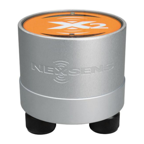
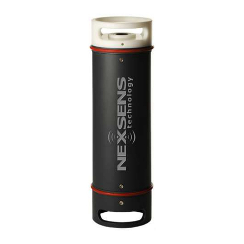
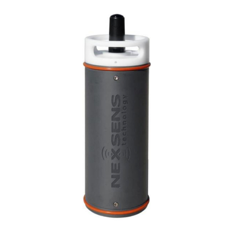
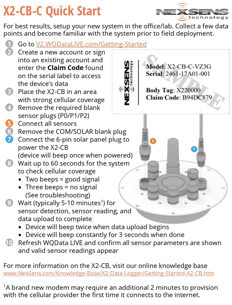
NexSens CB-150 Data Buoy User manual

CB-150 Data Buoy
User Guide
Last Revision: 8 October 2021
Date Generated: 25 October 2021
Copyright © 2021 NexSens Technology, Inc.

Table of Contents
1. General
CB-150 Data Buoy Overview
Key Components and Definitions
Key Specifications
CB-Series Data Buoy Planning & Precautions
2. Buoy Assembly
Using NexSens Electronics in CB-Series Data Buoys
Data Loggers
Battery Packs
Installing User-Supplied Electronics in CB-Series Data Buoys
Common Accessories
Securing Data Well Plate
CB-PTL Bulkhead Connector Assembly Installation
Connector Types
Installation
UW-6 Power Bulkhead Connector Assembly Wiring
UW6-BULK Pinout
Wiring Options
M550 Beacon for CB-Series Data Buoys
Installation
Operation
CB-Series Data Buoy Instrument Cage Installation
CB-CCA Anti-Rotation Collar
Use of Sacrificial Anodes on CB-Series Data Buoys
CB-Series Data Buoy Instrument Mounts
Topside Mounts
Subsurface Mounts
3. Deployment
CB-Series Data Buoy Ballast Weight & Stability
Top-Side Weight
Ballast Weight
Buoy Ballast Weights
Mooring Data Buoys
Buoy Ballast
Mooring Eye Lifting
Data Buoy Mooring Types
4. Troubleshooting and Maintenance
4
4
4
6
7
9
9
9
10
11
11
12
13
13
13
16
16
17
18
18
19
20
21
22
23
23
23
25
25
25
26
28
29
29
29
29
35
2

1. General
CB-150 Data Buoy Overview
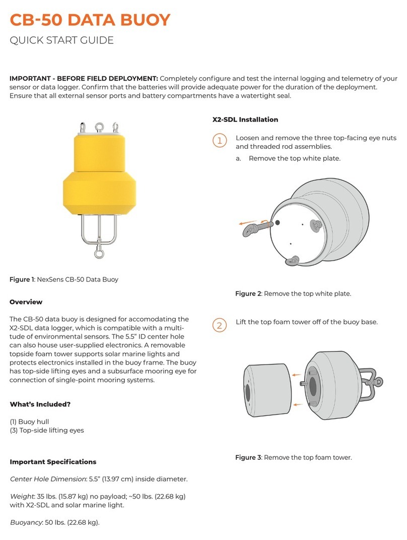
The CB-150 data buoy is a compact buoy platform designed for smaller water bodies, portable or
short-term deployments, and applications requiring small, power-efficient sensors. It is ideal for
deployment in lakes, rivers, coastal waters, harbors, estuaries, and other freshwater or marine
environments. Like all solar-powered NexSens CB-Series data buoys, it is a highly customizable
platform that may be configured with NexSens or user-supplied electronics. It supports a wide variety
of topside and subsurface sensors and measurement instruments.
Key Components and Definitions
Buoy Hull – Constructed of cross-linked polyethylene foam with a durable polymer outer layer and
rugged stainless steel frame providing a net buoyancy of 150 lb (68 kg). Three 2” passthrough holes
with female NPT bottom threads allow for quick connection of instrument deployment pipes and
custom sensor mounts.
Data Well – The waterproof compartment located in the center of the buoy hull for placement of
system electronics such as batteries and data loggers. On the CB-150 model, the data well has a 10.3”
(26.2 cm) diameter and 13.5″ (34.2 cm) height.
For complete NexSens systems, the data well is fitted with CB-A01-2 or CB-A05 battery harnesses
and the X2-CB data logger, which includes five sensor ports with waterproof UW connectors
supporting common standards such as SDI-12, RS-232 and RS-485. Waterproof sensor connection is
achieved by factory installation of fully-sealed UW connectors onto sensor cables.
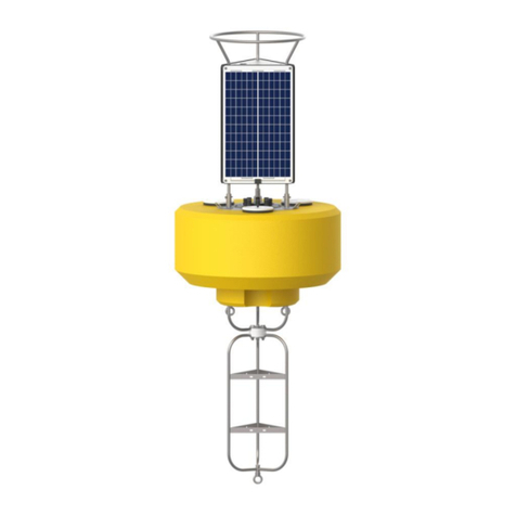
CB-150 data buoy.
4

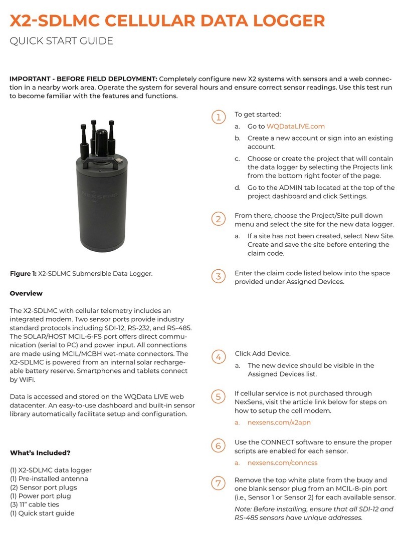
For users supplying their own electronics, the CB-150 is delivered as an open platform with empty data
well or with battery only. A data well top plate can be supplied in one of three ways:
1. A standard CB-PTL Pass Through Lid for passing of instrument cables through gland fittings
2. A CB-PTL lid with UW8-BULK sensor bulkhead cable assemblies
3. A blank lid with only UW6-BULK power cable assembly and vent that users may drill their own
holes and install connectors into
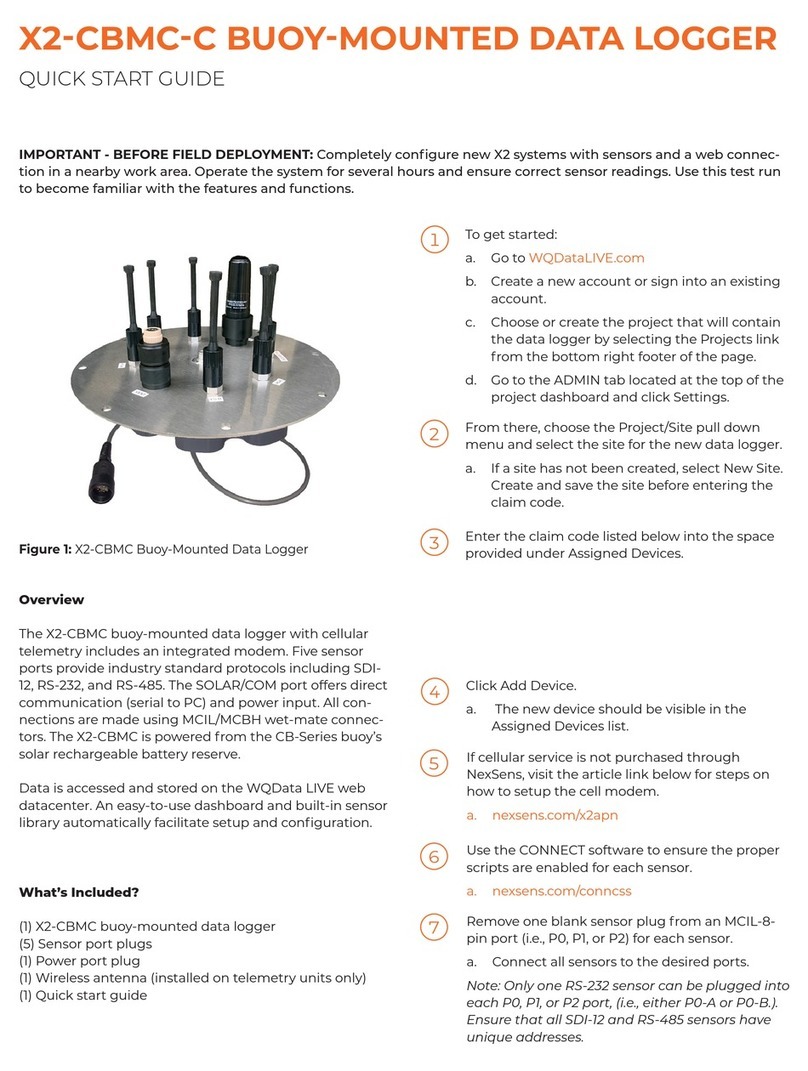
Solar Tower – Three 10W solar panels on the solar tower capture sunlight from any direction and
charge batteries located inside the data well. The tower also supports the mounting of an M550 solar
marine light for nighttime visibility. Aside from regular cleaning to ensure solar panels are unobstructed
from receiving maximum sunlight, there is little to no maintenance required. However, solar assemblies
may be function tested if any performance issue is suspected by placing in the sun and measuring
output on the UW-6 (6-pin) port plug.
Buoy data well and pass-
through holes. Data well top plate.
CB-150 solar tower.
5

Buoy Frame – The skeleton of the buoy is comprised of 316 stainless steel with topside lifting eyes
and subsurface mooring eyes for single and multi-point moorings. The frame supports attachment of
an instrument cage for secure connection of subsurface sensors and additional ballast weight for
stability.
Key Specifications
The key specifications of the CB-150 buoy are given below:
Hull Outer Diameter: 24.0” (61.0cm)
Hull Height: 14.0” (35.6cm)
Data Well Inner Diameter: 10.3” (26.2cm)
Data Well Height: 13.5″ (34.2cm)
Pass-Through Hole Diameter: 2.0″ (5.1cm)
Tower Height: 13.0” (33.00cm)
Solar Panels: 3x 10-watts
Weight: 100 lb (46kg)
Net Buoyancy: 150 lb (68kg)
Hull Material: Cross-linked polyethylene foam with polyurea coating & stainless steel deck
Hardware Material: 316 stainless steel
Mooring Attachments: 3x 3/4” eye nuts
CB-150 buoy frame with
instrument cage installed.
6

CB-Series Data Buoy Planning & Precautions
Buoy deployments are usually complex operations that involve many elements including sensors, data
loggers, mounting hardware and mooring equipment. Careful planning is essential to the success of a
buoy project, not only for system operation and data collection but also to ensure the project
personnel’s safety and minimize the risk of damage to expensive system components. When planning
a buoy deployment, be sure to give careful consideration to the following aspects:
Buoy sizing and power budget – Buoys come in various physical sizes with differing batteries and
solar charging capacities. A buoy must be adequately sized to tolerate the site environmental
conditions while providing sufficient power for continuous system operation. A power budget should be
calculated to ensure the system can meet the demand for sensor measurements and data
transmission.
Buoy ballast – Proper ballast of a buoy is critical to buoy stability when it is deployed in the water. Be
sure to review the ballast weight and stability guide when designing a buoy system. Some
experimentation may be required before final deployment.
Buoy mooring – Mooring systems come in many forms depending on the location, water depth, and
environmental conditions to which a buoy will be exposed. As a starting point, the mooring data buoys
guide provides an overview of common mooring strategies. However, NexSens does not endorse any
particular mooring strategy, and systems should be designed and executed based on careful
consideration and local knowledge of the deployment site.
Electrical connections – Many NexSens buoy systems utilize UW connectors for connection of
power and sensor cables. Data loggers such as the X2-CB have UW receptacle ports to receive
sensor cables fitted with UW plug connectors. UW connectors provide a double O-ring seal, with one
O-ring inside the receptacle and one around the plug. In order to ensure waterproof connection, check
the following each time a UW connection is made:
1. The O-ring inside the receptacle is present (has not fallen out)
2. The receptacle and plug are clean, dry and free of debris
3. The O-ring on the plug is lightly greased
4. Connection is tight, secure and fully seated
5. Unused receptacle ports are fitted with UW port plugs
Connections may be periodically inspected and maintained with O-ring grease, at a minimum before
each buoy deployment.
CB-Series data buoys contain a waterproof data well constructed of stainless steel where batteries are
mounted. Whenever installing or maintaining battery systems, use caution to avoid short-circuiting of
battery poles to the metal walls of the data well. Gloves and tools with rubber grips are recommended,
and any exposed connections should always be covered with electrical tape or other suitable
coverings.
7

Safe deployment – Above all else, safety is the most critical consideration to take during the planning
of a buoy deployment. Any time a buoy system is deployed, there are countless hazards, including, but
not limited to, working on/near water and lifting of heavy equipment. Important factors to consider for
personnel safety are:
Use of safety equipment (i.e., life jackets, gloves, steel toed boots, etc.,)
Proper lifting and mooring techniques
Awareness of on-site and surrounding weather conditions and advisories
Despite careful planning, unforeseen situations are always still a possibility. Buoy deployments are an
at-risk operation, and the user assumes liability for any injury or damages that may occur.
8

2. Buoy Assembly
Using NexSens Electronics in CB-Series Data Buoys
Although users may provide their own electrical components including data loggers, modems and
batteries, many CB-Series data buoys are delivered as complete, plug-and-play system packages with
a NexSens data logger as the central component of the system.
Data Loggers
NexSens offers four different data logging systems for buoy deployment, all of which are based on the
central processing unit of the X2 environmental data logger:
1. X2-SDL Submersible Data Logger – fully submersible unit designed for standalone operation or
installed in the CB-50 platform
2. X2-SDLMC Submersible Data Logger – fully submersible unit with topside wet-mate sensor
connectors for standalone operation or installed in the CB-25 platform
3. X2-CB Buoy-Mounted Data Logger – waterproof, lid-mounted package for integration on CB-
Series data buoys with data well and solar charging (model CB-150 and larger)
4. X2-CBMC Buoy-Mounted Data Logger – lid-mounted package with wet-mate connectors for use
on CB-Series data buoys in challenging environments such as offshore, typical on model CB-650
and larger
Reference the Data Loggers section of the NexSens Knowledge Base for resources including Quick
Start and User Guides to install, configure and operate NexSens data loggers with CB-Series data
buoys. Data logger user guides include detailed instructions on interfacing with sensors and setting up
transmission of data to the WQData LIVE web datacenter.
X2-SDL data logger. X2-SDLMC data logger. X2-CB data logger. X2-CBMC data logger.
9

Battery Packs
X2-SDL and X2-SDLMC data loggers rely on internal batteries to supply power. X2-CB and X2-CBMC
data loggers are designed for use on CB-Series data buoys with solar charging (model CB-150 and
larger). These buoys have a data well for installation of battery packs, and the data logger serves as
the top plate to provide a waterproof seal on the data well.
NexSens offers two standard types of battery harnesses, which include sealed lead acid (SLA)
batteries, solar regulator, mounting bracket and data logger connection cable pigtail (UW-6 connector):
1. CB-A01-2 – contains two 8.5 A-hr batteries (CB-150 only)
2. CB-A05-x – contains one to four 28 A-Hr batteries (depending on buoy capacity – see table
below)
The following table shows what battery harness models each CB-Series data buoy model has capacity
for in the data well. However, what model is selected should be based on a complete power budget
analysis that includes system power demand, solar charge capacity (panel size) and available sunlight
based on deployment location to aid in determining how much reserve battery power is needed.
CB-A01-2 CB-A05-1 CB-A05-2 CB-A05-3 CB-A05-4
CB-150 x x
CB-250 x x
CB-450 x x
CB-650 x x x
CB-950 x x x
CB-1250 x x x x
NexSens battery harnesses are typically shipped pre-installed in CB-Series data buoys. However, in
cases where batteries need to be installed or replaced, detailed instructions can be found here.
10

Installing User-Supplied Electronics in CB-Series Data Buoys
NexSens CB-Series data buoys are flexible platforms that allow for use with both NexSens and user-
supplied electronics. For those wishing to integrate their electronics, including batteries, data loggers,
and modems, several accessories are available to facilitate installation inside the watertight data well
located in the center of the buoy.
Common Accessories
Battery mounts – While user-supplied electronics systems may receive power from NexSens-issued
CB-A01-2 and CB-A05-x battery harnesses, users may also supply and install their battery and solar
regulator systems in the data well. The bottom of the data well has two welded standoffs for
connection of battery mount posts, and hardware for securing user-supplied batteries, including
mounting posts, brackets, and foam inserts. Consult a NexSens Applications Engineer for available
parts.
Data well plates – Buoys may be delivered with various data well top plate options:
CB-PTL pass-through lid with gland fittings for running user-supplied flying lead cables into the
data well, also compatible with bulkhead cable assemblies
Blank plate with only screw holes for users to drill custom hole patterns
No plate, user may machine custom plate using screw hole pattern from NexSens
In most cases, the CB-PTL is delivered with the buoy as it offers both flexibility and ease of use.
CB-PTL pass through lid.
11

Bulkhead cable assemblies – Ports on a CB-PTL may be interchanged with bulkhead cable
assemblies for power, RF signals and sensor data cables. The following options are available:
UW6-BULK – 6-pin power cables for connection of batteries, solar panels and regulator
RF-BULK – N-style female to SMA male RF cable assembly for use with modems placed inside
data well
UW-BULK – 8-pin sensor receptacle for use with sensor cables with factory-installed UW plug
connector; allows for external waterproof connection of user-supplied sensors
Instructions for installation and use of these bulkhead connector cables is available here.
Securing Data Well Plate
Any time the data well plate will be resealed, first verify that the large O-ring is in good condition, clear
of debris, and lightly greased. Align the plate with the bolt holes on the buoy and place the provided
bolts with lock washer. Tighten incrementally using a 9/16″ socket wrench in a cross-pattern as shown
below (2-3 passes recommended) to ensure even load distribution and proper seal of the data well.
UW6-BULK power cable
assembly.
RF-BULK antenna cable
assembly.
UW-BULK sensor cable
assembly.
Tighten bolts in a cross-pattern to seal properly.
12

CB-PTL Bulkhead Connector Assembly Installation
NexSens CB-Series buoy data wells capped with CB-PTL pass through lids may optionally have UW
plug ports replaced with bulkhead cable connector assemblies.
Connector Types
The CB-PTL comes standard with a UW-6 power bulkhead cable assembly (UW6-BULK) pre-installed.
Wiring instructions for connection of this cable to user-supplied electronics are available here.
The RF bulkhead connector assembly (RF-BULK) allows 3rd party modems to be integrated inside
CB-Series buoy data wells capped with CB-PTL pass through lids or blank lids with user-drilled holes.
It consists of an N-style female connector integrated on the bulkhead for external antenna connection,
and 1m pigtail cable with SMA male connector for connection to a modem placed inside the watertight
data well.
UW sensor bulkhead connector assemblies (UW-BULK) allow for pluggable, watertight connection of
sensor cables to user-supplied electronics in the data well. Sensor cables must have a factory-installed
UW connector for connection to the UW-BULK bulkhead receptacle.
Installation
Proper installation of bulkhead cable assemblies is essential in order to maintain the watertight integrity
of the data well. Installation of an RF-BULK cable assembly is shown below, but the procedure is the
same for UW6-BULK and UW-BULK cable assemblies.
1. Use a 1/8” Allen wrench, or equivalent tool, to loosen the nut from the threading on one of the
empty ports. Once loose, remove by hand and set aside.
Remove UW bulkhead plug.
13

2. Using the same tool, loosen the nut on the bulkhead cable and continue to unscrew by hand.
Double check that all O-rings are present when doing so.
3. Feed the bulkhead cable through the open space created by removing the UW bulkhead plug.
Once again, make sure the O-ring seals are present and free of debris.
Remove nut from bulkhead cable.
Place the bulkhead cable assembly.
14

4. Tighten the nut first by hand, then with a final ¼ turn using the Allen wrench in the first step to
secure in place, but do NOT overtighten.
5. Once installed, the nut may be secured using Marine Goop or equivalent sealer to prevent the nut
from slipping.
Tighten bulkhead cable assembly nut.
Seal nut to hold firmly in place.
15

UW-6 Power Bulkhead Connector Assembly Wiring
CB-Series Buoys without NexSens integrated electronics will ship with a solar tower and pass-through
plate outfitted with a UW-6 power bulkhead connector (UW6-BULK) port. Information regarding the port
pinout and different options for wiring power to user-supplied electronics is supplied below. For
installation instructions, follow the guide here.
UW6-BULK Pinout
The diagram and table below show the pinout of the UW-BULK cable assembly.
NexSens UW6-BULK power cable
assembly.
UW6-BULK pinout.
16

UW6-Bulk Pin # Molex Wire Color¹ Flying Lead Wire Color² Notes
1 – –
2 – –
3 Red – Solar Connector Jumps to Pin 6
4 Black Black
5 Yellow –
6 Orange Red Solar Connector Jumps to Pin 3
¹Molex connector is designed to interface with a NexSens CB-A01-2 or CB-A05-x battery harness. If
this accessory was not ordered, connector can be cut off to wire to user-supplied components.
²The Red and Black flying lead wires are intended to supply power to user-supplied electronics.
Wiring Options
Solar Charged Battery [most commonly used]
If power to the buoy electronics is to be maintained by a solar-charged battery and the buoy was not
delivered with a CB-A05-x or CB-A01-2 battery harness, a solar regulator and battery must be sourced
locally.
Molex Wire Solar Regulator Connection Battery Terminal Connection
Yellow Solar + –
Black Common/GND Negative (GND)
Orange Battery + –
Red – Positive (V+)
The internal jumper inside the solar panel connector disconnects battery power from on-board
electronics when the solar panel plug is removed from the UW6-BULK port. This simplifies system
storage as the data well does not need to be opened to manually disconnect the battery.
Battery ONLY
If solar charging is not required for the application, a user may source a standalone battery to supply
power to on-board electronics. The following wiring will direct battery power to the Red and Black flying
lead wires of the UW6-BULK.
Molex Wire Battery Terminal Connection
Orange Positive (V+)
Black Negative (GND)
Solar Panel ONLY
If the unregulated solar panel output is solely required to power instrumentation, connect:
Molex Wire Electronics Connection
Yellow V+
Black GND
17

M550 Beacon for CB-Series Data Buoys
The NexSens M550 Solar Marine Light is a common accessory added to NexSens CB-Series data
buoys up to and including the CB-450. Depending on the configuration, it has a 1-3 nautical mile range
and is normally delivered with flange mount hardware, yellow color and default 15 flash/minute pattern
(Model M550-F-Y).
Installation
While it typically comes pre-installed, the M550 can easily be removed and/or installed by the user.
Reference the M550 Installation Instructions for guidance with the standard flange mount version. The
pole mount option can be similarly fixed to the buoy top plate using the provided hardware and one of
the pre-drilled holes on the top plate.
M550 Solar Marine Light.
M550 pole mount option. Mounted to top plate.
18

CB-Series Data Buoy Instrument Cage Installation
The instrument cage attaches to the bottom of CB-Series buoys for water sensor deployments while
simultaneously lowering the center of gravity and increasing stability.
Model number CAGE is 39″ (99 cm) in length and is normally used with the CB-50, CB-150, CB-250
and CB-450 buoys. It is an optional accessory for the CB-50 and comes standard with the others.
Model number CAGE-L is 44″ (112 cm) in length and has a wider profile. It comes standard with CB-
650, CB-950 and CB-1250 buoys.
The cage is a critical component of the ballast weight of a data buoy and provides a mounting location
for additional ballast weight to be added as needed.
Attachment to the internal frame of a data buoy is simple using the provided hardware.
1. Use the provided bolt, lock washer and castle nut to attach the cage to the buoy frame.
Model CAGE instrument cage. Model CAGE-L instrument cage.
Bolt installation and cage connection.
20
Table of contents
Other NexSens Data Logger manuals

NexSens
NexSens X2-SDL User manual

NexSens
NexSens CB-1250 Data Buoy User manual

NexSens
NexSens X2-CBMC-C User manual

NexSens
NexSens X2 User manual

NexSens
NexSens X2-CB User manual

NexSens
NexSens X2-SDL User manual

NexSens
NexSens X2-CB-C User manual

NexSens
NexSens X2 User manual

NexSens
NexSens X2 User manual

NexSens
NexSens CB-50 Data Buoy User manual

NexSens
NexSens CB-1250 Data Buoy User manual

NexSens
NexSens X2-Cell User manual

NexSens
NexSens X2 User manual

NexSens
NexSens SDL500 User manual

NexSens
NexSens X2 User manual

NexSens
NexSens 3100-iSIC User manual

NexSens
NexSens X2 User manual

NexSens
NexSens X2-SDLMC User manual

NexSens
NexSens X2 User manual

NexSens
NexSens X2 User manual