Evers BPT-L19 User manual

Service manual
Battery-operated strapping tool for steel strapping
13, 16, 19 mm (1/2, 5/8, 3/4″)
BPT-L19
Evers GmbH Graf-Zeppelin-Str. 10 46149 Oberhausen Telefon +49 208 99475-0 Telefax +49208 99475-31 evers@eversgmbh.de eversgmbh.de

Validity:
●BPT-L19 from Series no L/21111001
Manufacturer
Signode Switzerland GmbH
Changes:
Version Date Visa Description
V 10.21 22.10.21 ak/hp DRAFT
V 11.21 24.11.21 ak/hp Corrections Preventive- and Corrective maintenance
© Copyright 2020 – All contents, in particular texts, photographs and graphics are protected by copyright. All rights,
including those rights for duplication, distribution and editing are reserved,
Signode Switzerland GmbH.
Evers GmbH Graf-Zeppelin-Str. 10 46149 Oberhausen Telefon +49 208 99475-0 Telefax +49208 99475-31 evers@eversgmbh.de eversgmbh.de
Works agency
Evers GmbH
Graf-Zeppelin-Straße
10-12
46149 Oberhausen

Table of contents
1 General information 4
1.1 Safety 4
1.2 Target group 4
1.3 Changes 4
2 Periodic maintenance 5
2.1 Implementation 5
2.2 Maintenance requirements table 6
2.3 Maintenance table 7
2.4 Clean the tool 8
2.5 Lubrication plan 8
3 Problemidentication 9
3.1 Diagnosis of mechanical or electro-mechanical faults 9
3.2 Diagnosis of electronic faults 11
3.3 Error lists 12
3.4 Service interface (PT-Studio) 19
4 Preventivemaintenancework(wearparts) 24
4.1 Re-greasing the tool 24
4.2 Cleaning/replacing the tension wheel 24
4.3 Cleaning/replacing jaws, notchers and cutter 25
5 Corrective maintenance work 26
5.1 Electronics components 26
5.2 Housing parts 27
5.3 Wiring components and switches 28
5.4 Mechanical components 29
5.5 Trigger 31
5.6 Wrap spring clutch unit 32
5.7 Tensioning system 32
5.8 Blocking of the sealing mechanism 34
5.9 Wiring 35
6 Electric diagram 37
7 Firmware-update 38
8 Product information 41
9 Contact 41
Evers GmbH Graf-Zeppelin-Str. 10 46149 Oberhausen Telefon +49 208 99475-0 Telefax +49208 99475-31 evers@eversgmbh.de eversgmbh.de

1 General information
The purpose of this service manual is to get experienced technicians familiar with the technical features of the tool,
in order to be independent in carrying out maintenance and repair work.
The current operating instructions and the document «Parts lists & Exploded drawings» of the tool as
well as the respective product information sheets are an integral component of this manual and must be
consulted in all cases.
Meaning of warning symbols. representation convections
DANGER
This text describes an extremely dangerous situation in which failure to observe the safety instruc-
tions will result in death or serious injury.
WARNING
This text describes a dangerous situation in which failure to observe the safety instructions can
result in death or serious injury.
CAUTION
This text describes a dangerous situation in which failure to observe the safety instructions can
result in minor injury.
ATTENTION
This text describes a situation that may lead to property damage or adverse operating results.
This text describes useful supplementing information.
►This symbol indicates handling steps.
– This symbol indicates results from the handling steps.
●This symbol indicates lists.
1.1 Safety
This manual must be read and understood by all persons who carry out repair and service work on the respective
strapping devices.
Use only original parts for repair and service work. Disregarding this may lead to damage to the device or
in the worst case, to personal injury.
1.2 Target group
This manual is intended for those technicians that are already familiar with the repair and service work of strapping
devices. The manual can also be used for training purposes for new employees.
1.3 Changes
The production lines and the technical design of the strapping devices are permanently optimised.
In case the respective changes have an inuence on the device performance, service or spare parts, a product
information shall be prepared.
A current version of the operating instructions and the document «Parts lists & Exploded drawings“ as well as the
respective product informations are a fundamental component of this manual and must also be observed.
!
Evers GmbH Graf-Zeppelin-Str. 10 46149 Oberhausen Telefon +49 208 99475-0 Telefax +49208 99475-31 evers@eversgmbh.de eversgmbh.de

5 of 42
2 Periodic maintenance
In order to ensure the highest-possible availability and to avoid subsequent damage caused by insucient lubricati-
on, periodic maintenance must be carried out in the device according to the following instructions.
The maintenance intervals are orientated according to the degree of usage (see maintenance requirements table
2.2) and the number of strapping cycles carried out. However, we recommend performing a service at least every
two years.
In addition, the details in the operating instructions (section 6.1) apply with regard to smaller maintenance work by
the customer.
2.1 Implementation
2.1.1 Cleaning
● Cleaning the tensioning and sealing area from abrasion and metal chips. This can be done with compres-
sed air assistance. Attention! It is essential to wear protective goggles with a good seal. Metal splinters
can be flung away by compressed air.
● Removal of excess contamination on other components of the device.
2.1.2 Visual check
● Is there any visible damage to the housing, base plates and other components that is relevant for its func-
tioning?
● Are all screws and other components that could be removed present and tight, and are they the original
part?
● Does the strap width setting match with the strap in use?
● Are all original wear parts with correct article number installed?
Refer to operating instructions (chapters 6.4, 6.5 and 6.6).
2.1.3 Function test
– Inserting the rechargeable battery: The backlight should illuminate briey
– Check the user interface function: Are all buttons functional? Select MAN Mode
– Operate the trigger: Testing the function of the strap insertion aid (on / o)
– Pull up the trigger and hold it. Press the tensioning
and sealing buttons one after the other:
With the lever pulled up, only one beeping tone sounds
per each button?
– Set the tool to „Manual“ operating mode. Prepare
the strapping, insert and tension the strap:
Is the strap tension range matching the strap size
(Plausibility check)?
– Actuate sealing button: Listen for noises. Is the seal correctly grasped? Is the
strap being cut? Does the backlight go green, is the
tool ready again?
– Remove the tool from the packaged goods: The end of the strap should remain in the tool. Can the
tool be easily removed from the seal?
– Check the seal: refer to operating manual, chapter 5.2
2.1.4 Maintenance
● If an error has occurred during the function test, rst continue with rectication according to chapter 3.
● Carrying out maintenance according to chapters 2.2, 2.3, 2.4 and 2.5.
2.1.5 Read out the cycle counter
►Touch the operating panel, the backlight lights up.
►Press the blank keypad between «Favourite» and
«operating mode».
►Raise the rocker lever. Now the number of cycles (2) is
displayed at the top of the display.
12
Evers GmbH Graf-Zeppelin-Str. 10 46149 Oberhausen Telefon +49 208 99475-0 Telefax +49208 99475-31 evers@eversgmbh.de eversgmbh.de

Average applications Heavy applications
Number of strappings 50 to 150/day 100 to 300/day
Environment – Indoor
– Industrial environment
– Room temperature (+/- 20°C)
– dry
– no abrasive substances present
– no corrosive vapours
– Outdoor covered
– Industrial environment
– Low temperature (< 5°C) or high (> 30°C) tempera-
tures or highly variable.
– Abrasive substances
– High humidity
Typical sectors – Steel/aluminium industry
– Rolling mills
– Tube and bar production
– Wire plants
– Construction industry
– Steel/aluminium industry
– Rolling mills
– Tube and bar production
– Wire plants
– Construction industry
Recommended
accessories
– Suspension bow if necessary
– Second battery if necessary
– Suspension bow if necessary
– Second battery if necessary
– Protection plate if necessary
Special measures: – Remove the battery from the tool if it
will not be used for a long time.
– When used outdoors, protect the tool from moisture
and wetness.
– If the tool has been accidentally exposed to moi-
sture, allow it to dry before using it again (remove
the battery).
– Remove the battery from the tool if it will not be
used for a long time.
Maintenance recommen-
dations (see also chapter
2.3)
– Clean the tool as required (compres-
sed air).
– Quarterly relubrication of the sea-
ling unit (see operating instructions,
chapter 6.3).
– Annual service by a specialist
– Clean the tool as required (Caution! Abrasive dust
should not be blown into the unit with compressed
air.
– Monthly relubrication of the sealing unit, see opera-
ting instructions, section 6.3).
– Half-yearly service by a specialist
2.2 Maintenance requirements table
The workload and need for maintenance of the tool may vary strongly depending on the operating environment. The required service work also diers accordingly. The table
below should provide a reference for categorising. The criteria are not to be understood as cumulative. The existence of one of the listed criteria is sucient for classication
in the higher category.
Evers GmbH Graf-Zeppelin-Str. 10 46149 Oberhausen Telefon +49 208 99475-0 Telefax +49 208 99475-31 evers@eversgmbh.de eversgmbh.de

2.3 Maintenance table
Description Parts list # Action Avarage
applications
(Cycles*)
Heavy
applications
(Cycles*)
Remarks
Tension wheel 116 Check/Replace As required Remove and check for wear or damage
Outer notcher
(2 pcs.)
169 Check/Replace or turn As required Remove and check for wear or damage
Jaws (2 pcs.) 161 Check/Replace As required Remove and check for wear or damage
Jaw axle(2 pcs.) 158 Check/Replace As required Remove and check for wear or damage
Jaw pin (2 pcs.) 163 Check/Replace As required Remove and check for wear or damage
Guidance bolt 180 Check/Replace As required Remove and check for wear or damage
Cutter 167 Check/Replace As required Remove and check for wear or damage
Connecting rod cpl. 61 Check/Replace 60‘000 50‘000 Remove. Check bearing and replace connecting rod if necessary.
Base plate 1 Check/Replace 60‘000 50‘000 Check the strap cutting edge for wear.
Roller 201 Check 60‘000 50‘000 It must be possible to turn the roller with little eort.
Toothed belt 58 Replace as preventive
measure
60‘000 50‘000
Toothed belt 38 Replace as preventive
measure
60‘000 50‘000
Belt pulley cpl. 94 Replace as preventive
measure
60‘000 50‘000 A defective or dirty freewheel can damage the motor axle.
Belt pulley cpl. 98 Replace as preventive
measure
60‘000 5‘0000 A defective or dirty freewheel can damage the motor axle.
* For the read out of the cycle counter, see chap. 2.1.5.
Evers GmbH Graf-Zeppelin-Str. 10 46149 Oberhausen Telefon +49 208 99475-0 Telefax +49 208 99475-31 evers@eversgmbh.de eversgmbh.de

2.4 Clean the tool
ATTENTION!
Do not use water or other solvent to clean.
See operating instructions, chap. 6.2.
2.5 Lubrication plan
Re-lubricate the device, see operating instructions (Manual), chap. 6.2 and 6.3.
Description Recommended lubricants Interval*
1Tension gear (except belts) (chapter 5.7.2) Klüber Microlube GBU-Y 131 60‘000 cycles
2Sealing gear (except belts) (chapter 5.4.3) Klüber Microlube GBU-Y 131 60‘000 cycles
3Freewheel (Attention: no grease!) (chapter 5.4.2) Universal oil e.g. WD 40 60‘000 cycles
4Pliers package cpl., all joints / bolts (chapter 4.1) Klüber Microlube GBU-Y 131 30‘000 cycles
5Back plate: guide for cross joint #190, guide to base plate
(chapter 5.4.1)
Klüber Microlube GBU-Y 131 30‘000 cycles
6Connecting rod cpl.: bearings, joins and bolts (chapter
5.4.1)
Klüber Microlube GBU-Y 131 30‘000 cycles
7Cutter guides (chapter 5.4.1) Klüber Microlube GBU-Y 131 30‘000 cycles
* see also maintenance table 2.3.
!
2
4
3
6
1
5
7
Evers GmbH Graf-Zeppelin-Str. 10 46149 Oberhausen Telefon +49 208 99475-0 Telefax +49208 99475-31 evers@eversgmbh.de eversgmbh.de

Symptom Possible cause Rectication
The strap is not
tensioned or is only
tensioned with low
force although the
feed wheel is rotating.
This is creating strap
particles and dust
1. The tensioning wheel is contaminated or worn
2. The tensioning unit is restricted in its freedom of
movement by a foreign body
3. The strap used is below the specied minimum strap
thickness
4. The base plate has a hairline crack
– Clean or replace the tensioning wheel
(chapter 4.2)
– Remove foreign objects
–Banddicke nach Spezikation wählen.
refer to operating instructions
(chapter. 7)
– Replace base plate.
The strap is not
tensioned or too little.
The feed wheel does
not turn although the
motor is running
1. The spring clutch does not engage.
2. The freewheel pressed into the belt pulley (# 98/94)
has malfunctions
3. The toothed belt slips
4. The sun gear pressed into the belt pulley or the spur
gear has slip
– Check the bushing (# 130) for smooth
running. (See chapter 5.6.1)
–Check bearing bolt (# 133) for tight t
(chapter 5.6.1).
– Replace belt pulley (# 98/94) (chapter
5.4.2).
Replace the toothed belt (# 38) and, if
necessary, the belt pulleys (# 98 and
94)
– Replace belt pulley (# 79) or cylindrical
gear
The strap tension is
released immediately
after the tensioning
process
1. The freewheel pressed into the gearbox housing has
malfunctions
– Replace freewheel
The tensioning pro-
cess cannot be star-
ted. A beep sounds
1. The battery was inserted after the strap was inserted
2. The signal „Rocker lever closed“ is missing. The
microswitch is defective
3. The signal „Rocker lever closed“ is missing. The
microswitch is not actuated
– Operate the trigger.
– Replace microswitch (# 240)
– Remove the mechanical cause
3 Problemidentication
Unexpected start-up in case of problem resolution, possible injuries.
Before any work on the tool, remove the rechargeable battery.
3.1 Diagnosis of mechanical or electro-mechanical faults
3.1.1 Tensioning process
The positions # in these tables refer to the positions in the document „Parts Lists & Explosions Drawings“.
Evers GmbH Graf-Zeppelin-Str. 10 46149 Oberhausen Telefon +49 208 99475-0 Telefax +49208 99475-31 evers@eversgmbh.de eversgmbh.de

3.1.2 Sealing and cutting procedure
Symptom Possible cause Rectication
The sealing is com-
pletely nished, the
green light appears,
but the strap is not cut
or not cut completely.
The notch is not deep
enough
1. The leading edge on the base plate is worn out
2. Plain bearing in connecting rod worn out
3. The cutting edge on the base plate is worn out or
or the clamping foot has a hairline crack
– Replace base plate (# 1)
– Replace connecting rod cpl. (# 61)
– Replace base plate (# 1)
The sealing unit is not
pulled up or not com-
pletely pulled up when
at rest
1. Shaft (# 188) is broken. – Check all parts involved
– Replace shaft (# 188)
The strap can only be
inserted into the base
plate with diculty or
not at all
1. Foreign body / strap remnants
2. Strap not according to specication.
– Clean / remove
–Use strap according to specication.
Symptom Possible cause Rectication
The tool remains on
the packaged goods
after the sealing
process and cannot be
detached
1. In automatic mode, the pliers remain on the seal to
prevent the tool from falling on the packaging
– Pull the trigger
3.1.3 Remove the tool from the packaged goods
Evers GmbH Graf-Zeppelin-Str. 10 46149 Oberhausen Telefon +49 208 99475-0 Telefax +49208 99475-31 evers@eversgmbh.de eversgmbh.de

11 of 42
3.2 Diagnosis of electronic faults
The tool errors can be divided into the following categories:
3.2.1 Operating error
The operator presses a button that is not intended at this moment of operation. Depending on the response of the
mechanics to an operating error, these may be further dierentiated.
● If the manipulation does not have any direct inuence on the mechanics, the error may only be indicated e.g. by
a beeping tone (and the current status of the tool controls will be maintained).
●If however it is to be expected that the mechanical components change to another mode (e.g. Tensioning -> In-
sert strap) when detecting an operating error, this is indicated by a beep tone and the tool control mode changes
accordingly.
Signallingexample(A1):
●short beep tone (0.4s)
●write Axx in “Application Error Code” object (no display)
3.2.2 Processing error
In the process ow, an event is detected that does not belong to the “normal” process (e.g. at a performance limit).
A change is accordingly carried out into an alternative tool control mode
Signallingexample(A2):
●2x short beep tones (0.2s, 0.2s Pause, 0.2s)
●write Axx in “Application Error Code” object (no display)
3.2.3 Temporary system error
This category of error is detected by the control unit and can be deleted by the operator by, for example, starting
a new strapping cycle. In doing so, the current cycle process is cancelled and as a result, is incorrect. If the error
recurs, the device should still be checked by the service centre.
Signallingexample(E1):
●beep tone (pulsating / medium)
●orange backlight
●(Application) Error Code Exx in Display (medium)
●Axx (is stored in History)
3.2.4 Static system error
These errors detected by the control unit cannot be deleted by the operator. Accordingly, the battery must be remo-
ved, the error rectied and the device must be reset by reinserting the battery (possibly recharged).
Signallingexample(E2):
●pulsating beep tone, long (5s)
●backlight red (or orange)
●Application) Error Code Exx in Display
●Axx (wird in History gespeichert)
Evers GmbH Graf-Zeppelin-Str. 10 46149 Oberhausen Telefon +49 208 99475-0 Telefax +49208 99475-31 evers@eversgmbh.de eversgmbh.de

3.3 Error lists
The following summary shows the errors to be detected by the strapping device
3.3.1 Tension process error
No. Process error System response Signalling Rectication
A10 Tension button pressed without releasing
the tension
No tensioning (A1) Short beeping
tone
Insert strap
A13 Trigger, tension button or sealing button
pressed during the tensioning process
[AUTO]
No tensioning (A1) Short beeping
tone
A14 Permissible number of cycles exceeded
[MAN]
No (more) tensioning (A1) Short beeping
tone
Tension again
A15 Tensioning process timeout Cancel tensioning
process
(A2) 2x short beeping
tone
Tension again
A16 Trigger switch pressed during clamping
process
Cancel tensioning
process
A2) 2x short beeping
tone
Retensioning
A18 Limit performance [MAN, SEMI] Cancel tensioning
process
(A2) 2x short beeping
tone
Retensioning
3.3.2 Sealing process error
No. Process error System response Signalling Rectication
A20 Sealing button (S5) activated without
release
No sealing (A1) Short beeping
tone
Insert and tension
the strap
3.3.3 Processing error “Insert strap”
No. Processing error System response Signalling Rectication
A11 Tensioning button (S1) pressed while
trigger pulled
No tensioning (A1) Short beeping
tone
A21 Sealing button (S1) pressed while trigger
pulled
No sealing (A1) Short beeping
tone
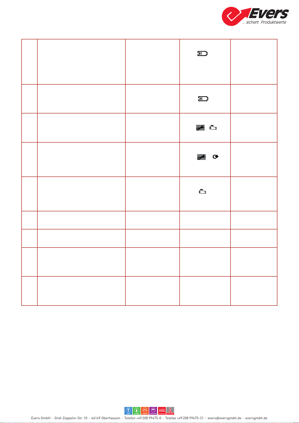
3.3.4 Processing error battery
No. Processing error System response Signalling Rectication
A11 Battery temperature too low (derating) Tensioning level will be
reduced
Symbols &
ash, force display
ashes
Increases auto-
matically at higher
battery temperature
Evers GmbH Graf-Zeppelin-Str. 10 46149 Oberhausen Telefon +49 208 99475-0 Telefax +49208 99475-31 evers@eversgmbh.de eversgmbh.de

3.3.5 System error battery
No. System error System response Signalling Rectication
E11 Invalid rechargeable battery type
Unknown rechargeable battery inserted,
invalid
– Incorrect rechargeable battery type
inserted
– Incorrect control print
– Control unit defective
No device function E2) Error Code, red
backlight,
symbol ashes,
pulsating beep tone,
long
– Insert the correct
rechargeable
battery
– Change the cont-
rol print
E20 Rechargeable battery high temperature
limit, temperature limit protection of the
rechargeable battery
– Rechargeable battery temperature >
60°C
No device function E2) Error Code, back-
light red,
symbol &
ashes, pulsating beep
tone, long
– Let the rechar-
geable battery
cool down
– Replace the
rechargeable
battery
E23 Rechargeable battery undervoltage,
undervoltage limit of the rechargeable
battery in operation reached
– Rechargeable battery empty
– Rechargeable battery too cold
Cancel current process
(with controlled positio-
ning)
Tensioning / welding
invalid!
No device function
(E2) Error Code, red
backlight,
symbol ashes,
pulsating beep tone,
long
– Charge the
rechargeable
battery
– Replace the
rechargeable
battery.
E24 Rechargeable battery coding error, coding
resistance cannot be detected (short-cir-
cuit / open)
– Rechargeable battery not inserted
correctly
– Coding resistance in the rechargeable
battery faulty
– Wiring to the rechargeable battery
adapter defective
No device function (E2) Error Code, red
backlight,
symbol ashes,
pulsating beep tone,
long
– Insert the rechar-
geable battery
correctly
– Replace the
rechargeable
battery
E25 Rechargeable battery temperature
measurement invalid, temperature sensor
(NTC) cannot be detected correctly
(short-circuit / open)
– Rechargeable battery not inserted
correctly
– Temperature sensor in the rechargeab-
le battery faulty
– Wiring to the rechargeable battery
adapter defective
No device function (E2) Error Code, back-
light red,
symbol &
ashes, pulsating beep
tone, long
– Insert the rechar-
geable battery
correctly
– Replace the
rechargeable
battery
E27 Idle run voltage level not reached
– Rechargeable battery empty
No device function (E2) Error Code, red
backlight,
symbol ashes,
pulsating beep tone,
long
– Let the rechar-
geable battery
cool down
– Replace the
rechargeable
battery
3.3.6 System error hardware
No. System error System response Signalling Rectication
E32 Internal electronics error
ESCON Internal Hardware Error (Error
Register Bit6) - control unit defective
No device function ((E2) Error Code, red
backlight,
symbol ashes,
pulsating beep tone,
long
– Replace the
control unit.
E33 Electronics high temperature limit
ESCON Thermal Overload Error (Error
Register Bit3) - control unit too hot - cont-
rol unit defective
No device function (E2) Error Code, red
backlight,
symbol ashes,
pulsating beep tone,
long
– Let the control unit
cool down.
– Replace the
control unit.
Evers GmbH Graf-Zeppelin-Str. 10 46149 Oberhausen Telefon +49 208 99475-0 Telefax +49208 99475-31 evers@eversgmbh.de eversgmbh.de
E34 Supply undervoltage
ESCON Vcc Undervoltage Error (Error
Register Bit1) - Supply only via USB
- Very low batter charge - control unit
defective
No device function (E2) Error Code, red
backlight,
symbol ashes,
pulsating beep tone,
long
– Let the rechar-
geable battery
cool down
– Replace the
rechargeable
battery
– Replace the
control unit.
E35 Supply overvoltage
ESCON Vcc Overvoltage Error (Error
Register Bit0)
Cancel current process (E1) Error Code, oran-
ge backlight,
symbol ashes,
pulsating beep tone,
average
In case of repetition
– Replace the
control unit
E36 5 V Supply undervoltage ESCON +5V
VDC Undervoltage Error (Error Register
Bit2)
– Motor Hall sensors / Encoder defective
– Control unit defective
No device function (E2) Error Code, red
backlight,
symbol & pul-
sating beep tone, long
– Motor / replace
wiring
– Replace the
control unit
E37 End stage overvoltage
ESCON Overcurrent Error (Error Register
Bit4)
– Wiring to the motor defective
– Motor defective
– Control unit defective
Cancel current process (E1) Error Code, oran-
ge backlight,
symbol & pul-
sating beep tone,
average
In case of repetition
– Motor / replace
wiring
– Replace the
control unit
E39 Encoder error
ESCON Encoder errors (Error Register
Bit16, 17)
– Wiring to the encoder defective
– Motor encoder defective
– Control unit defective
No device function (E2) Error Code, red
backlight,
symbol pulsating
beep tone, long
– Motor / replace
wiring
– Replace the
control unit
E40 Internal drive software error ESCON
Internal Software Errors (Error Register
Bit25, 27)
Cancel current process (E1) Error Code, oran-
ge backlight, pulsating
beep tone, average
In case of repetition
– Replace the
control unit
E41 Internal software error
Internal Application Error (Error Register
Bit26?)
Cancel current process (E1) Error Code, oran-
ge backlight, pulsating
beep tone, average
In case of repetition
– Replace the
control unit
E42 Display does not detect incorrect display
identication
– Incorrect display print
– Incorrect control print
No device function (E2) Output not pos-
sible! Pulsating beep
tone, long
– Install correctly
Display Print
– Install correctly
Control Print
E43 Display communication error faulty com-
munication with display
– Poor Flexprint display
– Display defective
– Control unit defective
No device function (E2) Output not pos-
sible! Pulsating beep
tone, average
– Replace Flexprint
display
– Replace display
– Replace the
control unit
Evers GmbH Graf-Zeppelin-Str. 10 46149 Oberhausen Telefon +49 208 99475-0 Telefax +49208 99475-31 evers@eversgmbh.de eversgmbh.de

3.3.7 System error process
No. System error System response Signalling Rectication
E50 Abort sealing: Trigger pulled (S4:0) Cancel sealing process. (E2) Error Code, oran-
ge backlight,
symbol pulsating
beep tone, average
Incorrect sealing.
– Repeat strapping
– Replace operating
lever switch
E53 Timeout sealing mechanism (S3)
– Mechanical components jammed
– Cam switch / wiring defective
Cancel sealing process. (E2) Error Code, red
backlight,
symbol pulsating
beep tone, long
Incorrect sealing.
– Repeat strapping
– Clean mechanical
components
– Check/replace
home switch S3
E54 Timeout sealing process (End position not
found)
– Mechanical components jammed
– An attempt was made to seal a strap
that had already been sealed.
Cancel welding process. (E2) Error Code, red
backlight,
symbol pulsating
beep tone, long
Incorrect sealing.
– Repeat strapping
– Clean mechanical
components
– Multiple sealings
are not permitted.
E55 Performance limitation [AUTO] Cancel tensioning pro-
cess.
(E1) Error Code, oran-
ge backlight,
symbol &
pulsating beep tone,
average
– Repeat auto
tensioning.
E56 Timeout tensioning process [AUTO] Cancel tensioning pro-
cess.
(E1) Error Code, oran-
ge backlight, pulsating
beep tone, average
– Repeat auto
tensioning.
E57 Strap torn or slipped Cancel tensioning
process
idle state, BE = 0
(E1) Error Code, oran-
ge backlight, pulsating
beep tone, average.
Symbol ashes
– Reduce tensioning
force
– Insert the strap
again.
– Clean or replace
the tensioning
wheel
E60 Crimp mechanism not initialised. Crimp
mechanism not in home position
Cancellation of the
switch-on process. Tool
tries to nd the home
position
(E2) Error Code, oran-
ge backligh,
Symbol
pulsating beep tone,
average
– Crimp mechanism
initialise (Homing)
E61 Timeout Initialisation of the crimping me-
chanism (homing)
Abort initialisation crimp
mechanism
(E2) Error Code, red
backligh,
Symbol
pulsating beep tone,
long
In case of recurrence:
– Home switch S3
mech. actuation
check
– Replace Switch S3
– Engine diagnosis
carry out
E62 Crimp current has exceeded higher war-
ning level
(E1) Error Code, oran-
ge backligh,
Symbol
pulsating beep tone,
average
Crimping may not be
correct:
– Check/clean me-
chanics
– Check wear parts
E63 Crimp current has not exceed lower
warning level
(E1) Error Code, oran-
ge backligh,
pulsating beep tone,
average
Crimping may not be
correct
E64 Crimping current has exceeded maximum
permissible current
Abbruch Crimpvorgang (E2) Error Code, red
backligh,
Symbol
pulsating beep tone,
average
Crimping not correct
→ Repeat the strap-
ping process
– Check/clean me-
chanics
– Check wear parts
Evers GmbH Graf-Zeppelin-Str. 10 46149 Oberhausen Telefon +49 208 99475-0 Telefax +49208 99475-31 evers@eversgmbh.de eversgmbh.de

3.3.8 System error battery (Schematic presentation)
3.3.9 System error hardware (Schematic presentation)
E20 E23E11 E25E24 E27
Invalid type Temperature
> 60
°C / 140°FUndervoltage Error
coding
Error
temperature
measuring
Idle run
voltage too
low
Insert
correct
battery
Let battery
cool
down
Charge battery Insert battery correctly Charge battery
Change
PCB Replace battery
E33 E34 E35 E37E32 E36
Internal
electronics
error
Electronic
high
temperature
Supply
undervoltage
Supply
overvoltage
End stage
overvoltage
Let control
unit cool
down
Charge battery
5V Supply
undervoltage
Replace motor / wiring
Replace battery
Replace PCB, at E35 and E37 only in case of reccurence
Evers GmbH Graf-Zeppelin-Str. 10 46149 Oberhausen Telefon +49 208 99475-0 Telefax +49208 99475-31 evers@eversgmbh.de eversgmbh.de

3.3.10 System error process (Schematic presentation)
E43E42E39 E40 E41
Encoder error
Internal drive
SW error
Internal drive
SW error
Display not
detected
Display
communication
error
Replace
motor / wiring
Instal correct
display
Replace exprint
cable
Install
correct PCB
Replace
display
Replace PCB (control unit)
E50 E53 E54 E55 E57E56
Abort welding
open lever
Timeout
sealing
mechanism
Timeout
sealing process
Performance
limitation
(AUTO)
Timeout 10s
Tensioning
(AUTO)
Strap torn or
slipped
Incorrect sealing, repeat
Reduce
tensioning
force
Repeat tensionng
Replace opera-
ting lever switch
Insert the
strap again
Check / clean mechanics Question the application
Replace cam
switch
or wiring
Clean or replace
tension wheel /
tooth plate
Evers GmbH Graf-Zeppelin-Str. 10 46149 Oberhausen Telefon +49 208 99475-0 Telefax +49208 99475-31 evers@eversgmbh.de eversgmbh.de

E60 E61 E62 E63 E64
Sealing mecha-
nism not
on home position
Timeout Initializati-
on of the crimping
mechanism
(Homing)
Crimp current has
exceeded higher
warning level
Crimp current has
not exceeded
lower warning level
Crimping current
has exceeded
maximum permis-
sible current
Check mechanical
actuation of home
switch S3
Initialise crimp
mechanism
(Homing)
Crimping may not be correct.
Check, repeat if necessary
Check / clean mechanics
Check wear parts
Replace swich
S3
Carry out engine
diagnosis
Evers GmbH Graf-Zeppelin-Str. 10 46149 Oberhausen Telefon +49 208 99475-0 Telefax +49208 99475-31 evers@eversgmbh.de eversgmbh.de

3.4 Serviceinterface(PT-Studio)
With the Packaging Technology Studio (PT-Studio), the service technician is provided with a tool that helps to iden-
tify problems with the periphery system of the electronics, the electronics themselves and the motor.
The scope of the diagnostics includes the following points:
●Motor
● Hall eect sensors
●Encoder
●LCD display
●Switches and connections
●Buzzer
3.4.1 Starting PT-Studio and connecting to the device
The program does not have to be installed. Execute the File “Packaging Technology Studio” to start.
►Then remove two screws (# 283) of the LCD operating unit. Lift the operating unit to release it and only lift it so
far that the Micro USB connector can be accessed.
►Insert the battery in the tool and then connect to a computer using a USB connecting cable (USB 2.0 connector
A - USB 2.0 connector Micro-B).
Evers GmbH Graf-Zeppelin-Str. 10 46149 Oberhausen Telefon +49 208 99475-0 Telefax +49208 99475-31 evers@eversgmbh.de eversgmbh.de

If the controller is not automatically recognised, stablish the connection of PT Studio to the tool, click on the icon
“Search controller”.
With the rst connection, PT Studio requests the rmware le loaded on the tool. This is stored in the “Packaging
Technology Studio“ folder.
● Using Explorer, highlight the respective le, while observing the version (displayed in red), and conrm with OK.
The connection is being made. Now PT Studio communicates with the device and data is transferred.
3.4.2 Diagnostics
Double click on the “Diagnostics” icon to start the diagnostics.
►Follow the instructions in English.
Evers GmbH Graf-Zeppelin-Str. 10 46149 Oberhausen Telefon +49 208 99475-0 Telefax +49208 99475-31 evers@eversgmbh.de eversgmbh.de
Other manuals for BPT-L19
1
Table of contents
Other Evers Power Tools manuals


Popular Power Tools manuals by other brands


GYS
GYS POWERDUCTION 10R Translation of the original instructions

Jet
Jet ETM-949EVS operating instructions

Bomag
Bomag BPR 30/38-3 Operating instructions and Maintenance instructions

VOLTGEAR
VOLTGEAR PLUS+ 6500230 manual

Toyama
Toyama TDPC170WRCT-XP owner's manual

Parkside
Parkside PMFW 310 C2 Translation of the original instructions