SSP Safety Simplifier User manual
Safety Simplifier Manual
Design, programming, installation, maintenance and decommissioning of Safety Simplifier
Systems.
Safety Simplifier makes it easy to create safe and reliable industry and
workplace environments, using wireless safety communication.
Safety Simplifier can be customized with many different features and
functions to fit your application.
SSP North AB 30/08/2018 Manual V2f
2

SSP North AB 30/08/2018 Manual V2f
3
This document is the original document
All rights of this documentation are reserved by SSP North AB (Safety System Products North AB).
Copies may be made for internal uses.
Source code from third-parties and/or open source software has been used for some parts of the
configuration software. The relevant license information available tough our home page
(www.sspn.se).
SSP North AB
Tullkammarvägen 14
439 31 Onsala
Sweden
www.sspn.se

SSP North AB 30/08/2018 Manual V2f
4
Table of Contents
1Introduction ..........................................................................................................10
1.1 This Manual ........................................................................................................10
1.1.1 Abbreviations ..................................................................................................................... 10
1.1.2 Symbols ............................................................................................................................. 10
1.2 Intended use of Safety Simplifier ........................................................................10
1.3 Contact ...............................................................................................................11
1.4 Who can implement Safety Simplifier..................................................................11
1.5 Warranty .............................................................................................................11
1.6 Maintenance and repairs ....................................................................................11
1.7 Disposal considerations ......................................................................................11
1.8 Safety Assessment .............................................................................................12
1.9 Safety communication ........................................................................................12
2The Safety Simplifier System overview and features ........................................13
2.1 Features .............................................................................................................14
2.1.1 Example input functions .................................................................................................... 14
2.1.2 Example Output Functions ................................................................................................ 14
2.1.3 Combined I/O..................................................................................................................... 14
2.1.4 Redundant Relay Outputs ................................................................................................. 15
2.1.5 I/O outputs for “non-safety” information............................................................................. 15
2.1.6 LED information ................................................................................................................. 15
3Safety Precautions when using Safety Simplifier ..............................................16
3.1 Safety information regarding I/O and relay outputs of Safety Simplifier...............19
3.1.1 The relay outputs ............................................................................................................... 19
3.1.2 Solid-state transistor outputs ............................................................................................. 20
3.1.3 Safety inputs ...................................................................................................................... 22
4Technical data Safety Simplifier..........................................................................23
4.1 Safety parameters according to 610508 .............................................................25
5Dimensions and mounting ..................................................................................26
6Safety Simplifier principle layout ........................................................................29
7Electrical Installation ...........................................................................................30
7.1 Making IO Connections.......................................................................................31
8Bus communication via radio and/or CAN-bus..................................................32
9Calculating PFH-d values ....................................................................................32
10 Calculating reaction time.....................................................................................34
11 Electrical diagrams for recommended connections of machines, PB:s and
safety devices.....................................................................................................................35
11.1 E-stop, Combo PB with indication could be used for reset, open, start, stop etc .35
11.2 E-stop, Combo PB with indication for Reset, Open, Start and Stop, Selectors....35

SSP North AB 30/08/2018 Manual V2f
5
11.3 Two-hand connection according to EN 574.........................................................36
11.4 Safety devices with OSSD outputs such as: RFID- sensor/Safety Gate sensor,
Scanners, Light beams and light curtains .............................................................................36
11.5 Safety Gate limit switches..................................................................................37
11.6 Relay outputs for contactors with feedback for supervision/monitoring ..............37
11.7 Relay outputs for machines and safety devices .................................................38
11.8 OSSD outputs for machines, contactors and safety devices ..............................38
11.9 The LED display menu.......................................................................................39
11.9.1 Navigation.......................................................................................................................... 39
11.9.2 Sub-menus ........................................................................................................................ 40
11.9.3 The menus......................................................................................................................... 41
11.9.3.1 N (first level)....................................................................................................................... 41
11.9.3.2 N (second level)................................................................................................................. 41
11.9.3.3 I/O (first level) .................................................................................................................... 42
11.9.3.4 I/O (second level)............................................................................................................... 43
11.9.3.5 U (first level)....................................................................................................................... 43
11.9.3.6 U (second level)................................................................................................................. 44
11.9.3.7 U (third level) ..................................................................................................................... 44
11.9.3.8 M (first level) ...................................................................................................................... 45
11.9.3.9 M (second level) ................................................................................................................ 45
11.9.3.10 (Radio) (first level) ........................................................................................................ 46
11.9.3.11 (Radio) (second level) .................................................................................................. 46
11.9.3.12 CAN (first level).................................................................................................................. 47
11.9.3.13 CAN (second level)............................................................................................................ 47
11.9.3.14 CAN (third level) ................................................................................................................ 48
11.9.4 Fatal error mode ................................................................................................................ 48
11.9.4.1 Fatal error codes................................................................................................................ 48
11.9.5 Configuration mode ........................................................................................................... 50
11.10 LED Display quick reference...............................................................................51
11.10.1 First level menu information .............................................................................................. 51
11.10.2 Second level menu information ......................................................................................... 51
11.10.3 Third level menu information ............................................................................................. 52
12 Introduction of the software Simplifier Manager................................................54
13 Simplifier Manager ...............................................................................................54
13.1 Notice .................................................................................................................54
13.2 Windows 7 and 10 ..............................................................................................54
13.3 Installation ..........................................................................................................54
13.3.1 External Tools .................................................................................................................... 54
13.3.1.1 Compiler ............................................................................................................................ 54
13.3.1.2 PDF Viewer........................................................................................................................ 54
13.3.1.3 Windows 7 USB Driver ...................................................................................................... 54
13.4 User Interface Layout .........................................................................................55
13.4.1 The Main Menu.................................................................................................................. 55
13.4.2 The Toolbar........................................................................................................................ 58
13.4.3 Documents......................................................................................................................... 58
13.4.4 The Toolbox ....................................................................................................................... 58
13.4.5 The Inspector..................................................................................................................... 58
13.4.6 The Project Manager ......................................................................................................... 58
13.5 Making your first program ..................................................................................58
13.5.1 Creating a Project .............................................................................................................. 58
13.5.2 Hardware Configuration..................................................................................................... 59
13.5.3 The Logic Editor................................................................................................................. 60
13.5.4 Navigation in the logic graph ............................................................................................. 61

SSP North AB 30/08/2018 Manual V2f
6
13.5.5 The Goal of this example................................................................................................... 61
13.5.6 Adding Function Blocks ..................................................................................................... 62
13.5.7 Moving Blocks.................................................................................................................... 63
13.5.8 Deleting Blocks .................................................................................................................. 63
13.5.9 Selecting Multiple Blocks................................................................................................... 63
13.5.10 Copy, Cut, and Paste......................................................................................................... 63
13.5.11 Connections....................................................................................................................... 63
13.5.12 Removing Connections ..................................................................................................... 64
13.5.13 Final steps ......................................................................................................................... 65
13.5.14 Checking and Compiling.................................................................................................... 65
13.5.15 Saving and loading projects .............................................................................................. 65
13.6 Expanding the program.......................................................................................66
13.6.1 Local Memories ................................................................................................................. 66
13.6.2 Adding Local Memories to the program ............................................................................ 67
13.6.3 Managing Pages................................................................................................................ 68
13.6.4 Adding more nodes ........................................................................................................... 70
13.6.5 Programming Node 2 ........................................................................................................ 70
13.6.6 Sending Information via Radio/CAN.................................................................................. 71
13.7 Online Mode .......................................................................................................74
13.8 Downloading Programs.......................................................................................77
13.8.1 Entering serial numbers..................................................................................................... 78
13.8.2 Download via USB............................................................................................................. 78
13.8.3 Download via radio with Simplifier Monitor........................................................................ 78
13.9 Passwords .........................................................................................................78
13.9.1 Opening a password protected project file ........................................................................ 79
13.9.2 Comments ......................................................................................................................... 79
13.9.3 The Comment property...................................................................................................... 79
13.9.4 The Comment block .......................................................................................................... 79
13.10 Designing systems with Radio or CAN communication.......................................80
13.10.1 Radio and CAN communication safety Notice .................................................................. 80
13.10.2 Radio ................................................................................................................................. 81
13.10.3 Selecting radio channel for radio communication.............................................................. 83
13.10.4 Designing systems that communicate via radio ................................................................ 84
13.10.4.1 Radio quality ...................................................................................................................... 84
13.10.5 Global and CAN Memories................................................................................................ 86
13.10.5.1 Choosing Memory Numbers.............................................................................................. 86
13.10.5.2 Timeout and StartUp test................................................................................................... 86
13.10.5.3 Best Practices.................................................................................................................... 88
13.10.5.4 Controlling outputs directly via radio or CAN..................................................................... 88
13.11 Input Functions ...................................................................................................89
13.11.1 Input States........................................................................................................................ 90
13.11.2 Input signal types............................................................................................................... 91
13.11.2.1 VDC ................................................................................................................................... 91
13.11.2.2 OSSD................................................................................................................................. 91
13.11.2.3 0V ...................................................................................................................................... 91
13.11.2.4 A, B, C, D Pulses ............................................................................................................... 91
13.11.2.5 Inverted A, B, C, D Pulses ................................................................................................. 91
13.11.3 Input properties.................................................................................................................. 91
13.11.3.1 Enable ERROR Output...................................................................................................... 92
13.11.3.2 StartUp Test ....................................................................................................................... 92
13.11.3.3 Filter ON (ms) .................................................................................................................... 92
13.11.3.4 Filter OFF (ms) .................................................................................................................. 92
13.11.3.5 Enable Simultaneity........................................................................................................... 92
13.11.3.6 Simultaneity (ms) ............................................................................................................... 92
13.11.3.7 Enable Zero Time .............................................................................................................. 93
13.11.3.8 Zero Time (ms) .................................................................................................................. 93

SSP North AB 30/08/2018 Manual V2f
7
13.11.3.9 Comment ........................................................................................................................... 93
13.11.3.10 Terminal Count............................................................................................................... 93
13.11.3.11 Pin Properties ................................................................................................................ 93
13.12 Output Functions ................................................................................................94
13.12.1 ERROR State .................................................................................................................... 95
13.12.2 Feedback ........................................................................................................................... 96
13.12.3 Output signal types ............................................................................................................ 96
13.12.3.1 VDC ................................................................................................................................... 96
13.12.3.2 0V ...................................................................................................................................... 96
13.12.3.3 OSSD................................................................................................................................. 96
13.12.3.4 A, B, C, D Pulses ............................................................................................................... 96
13.12.3.5 Inverted A, B, C, D Pulses ................................................................................................. 96
13.12.4 The Advanced Output function block................................................................................. 96
13.13 Fatal Errors.........................................................................................................97
13.14 Logic...................................................................................................................97
13.14.1 Logical Loops..................................................................................................................... 97
13.14.2 Unsafe and safe signals .................................................................................................... 98
13.15 Serial Communication for status information.......................................................99
13.15.1 Serial Encoding.................................................................................................................. 99
13.15.1.1 Format ............................................................................................................................. 100
13.15.2 Serial Decoding ............................................................................................................... 101
13.15.3 Serial communication via I/O Terminals .......................................................................... 102
13.15.4 Configuration for communication with other PLCs .......................................................... 103
13.15.4.1 Receiving signals from other PLCs ................................................................................. 103
13.15.4.2 Sending signals to other PLCs ........................................................................................ 103
13.15.4.3 Function blocks for communication with PLCs................................................................ 103
14 Function Block Reference .................................................................................104
14.1 Inputs................................................................................................................105
14.1.1 Two-Hand Device ............................................................................................................ 105
14.1.2 Status Input...................................................................................................................... 107
14.1.3 Selector Switch ................................................................................................................ 108
14.1.4 Advanced Input................................................................................................................ 109
14.1.5 Door Sensor......................................................................................................................111
14.1.6 Light Barrier ......................................................................................................................112
14.1.7 E Stop ...............................................................................................................................114
14.1.8 Push Button ......................................................................................................................115
14.2 Output...............................................................................................................116
14.2.1 Advanced Output ..............................................................................................................116
14.2.2 OSSD Output....................................................................................................................117
14.2.3 Relay Output.....................................................................................................................118
14.2.4 Status Output....................................................................................................................119
14.3 Memory ............................................................................................................120
14.3.1 Memory............................................................................................................................ 120
14.3.2 Reference ........................................................................................................................ 121
14.4 Function............................................................................................................122
14.4.1 Delay OFF ....................................................................................................................... 122
14.4.2 Delay ON ......................................................................................................................... 123
14.4.3 Single Reset .................................................................................................................... 124
14.4.4 Sequence Reset .............................................................................................................. 125
14.4.5 Stepping........................................................................................................................... 126
14.4.6 Internal Input.................................................................................................................... 127
14.5 Logic.................................................................................................................129
14.5.1 NOT ................................................................................................................................. 129

SSP North AB 30/08/2018 Manual V2f
8
14.5.2 AND ................................................................................................................................. 129
14.5.3 NAND............................................................................................................................... 130
14.5.4 OR ................................................................................................................................... 132
14.5.5 NOR................................................................................................................................. 133
14.5.6 XOR ................................................................................................................................. 134
14.5.7 XNOR .............................................................................................................................. 135
14.6 Latches.............................................................................................................136
14.6.1 T Latch ............................................................................................................................. 136
14.6.2 SR Latch .......................................................................................................................... 137
14.7 Signal Generators.............................................................................................138
14.7.1 Logic 1 ............................................................................................................................. 138
14.7.2 Logic 0 ............................................................................................................................. 138
14.7.3 Square Wave ................................................................................................................... 139
14.7.4 1Hz Blink.......................................................................................................................... 139
14.7.5 5Hz Blink.......................................................................................................................... 140
14.8 Debug...............................................................................................................142
14.8.1 Fatal Error........................................................................................................................ 142
14.8.2 CAN OK ........................................................................................................................... 143
14.8.3 Link OK ............................................................................................................................ 143
14.9 Advanced .........................................................................................................144
14.9.1 Unsafe & Safe.................................................................................................................. 144
14.10 Non-Safety........................................................................................................144
14.10.1 Serial Encoder ................................................................................................................. 144
14.10.2 Serial Decoder ................................................................................................................. 146
14.11 Miscellaneous...................................................................................................147
14.11.1 Comment ......................................................................................................................... 147

SSP North AB 30/08/2018 Manual V2f
9
Safety Simplifier
Introduction | System overview | Features | Safety
Precautions | I/O and Relay outputs | Technical data |
Installation | Bus communication | PFH-d-values |
Reaction time | Electrical diagrams | LED display

SSP North AB 30/08/2018 Manual V2f
10
1 Introduction
1.1 This Manual
This manual regards the design and use of Safety Simplifier systems.
The manual is valid until new documentation is published. The latest original instructions are available
at www.sspn.se.
The manual explains the function, the special safety design to consider for a safety system, the
calculation of safety values for Safety Simplifier as an element of safety and how to connect and install
the product.
Programming, downloading, updating and debugging Simplifier Systems is described in the software
part of this manual.
1.1.1 Abbreviations
CAN
Controller Area Network
DC
Diagnostic coverage
ESPE
Electro-sensitive Protective Device
EUC
Equipment Under Control
MRT
Mean Repair Time
OSSD
Output Signal Switching Device
PCB
Print Circuit Board
PFH
Mean probability of failure on demand
PFH-d
Mean probability of dangerous failure on demand
PL
Performance Level
PLC
Programmable Logic Controller
SFF
Safe Failure Fraction
SIF
Safety Instrumented Function
SIL
Safety Integrity Level
SSPN
Safety System Products North AB
USB
Universal Serial Bus
1.1.2 Symbols
Different symbols are used throughout this manual and it is important to understand the meaning of
each.
Warning!
This symbol indicates a situation that presents immediate danger, and if not
prevented will result in serious injury or death.
Caution!
This symbol indicates a situation that presents potential danger, and if not prevented
may result in injury or death.
Notice!
This symbol indicates a potential danger, which may lead to damage to property and
equipment if not prevented.
Note
This symbol indicates useful tips and information.
1.2 Intended use of Safety Simplifier
The Safety Simplifier is intended for use in machinery covered by the Machinery Directive 2006/42/EC
and for safety circuits according to ISO 13849-1 and IEC 61508 up to PL e, Cat. 4 and SIL 3. See
technical data and CE declaration for Safety Simplifier for more information on intended use.

SSP North AB 30/08/2018 Manual V2f
11
1.3 Contact
In case of a hazardous malfunction of a safety simplifier please contact SSP North AB using the
contact information on the last page of this document. All necessary contact information can also be
found at www.sspnorth.se. SSP North AB can also be contacted through their distribution network as
they are responsible to forward information which can be vital for the correct use and to prevent
hazardous situations.
1.4 Who can implement Safety Simplifier
The Safety Simplifier may only be assembled, installed, programmed, commissioned, maintained and
decommissioned by personnel of sufficient competence. Competent personnel are people who:
•have knowledge in operating the equipment in systems which Safety Simplifier will be a part of
•have knowledge in Safety Standards such as the machinery directive and other standards
applicable to the application
•have knowledge in basic electronics
•have knowledge in the programming of Safety PLC-Systems
•have got training in using Safety Simplifier and Simplifier Manager
•have read and understood the contents of this manual
When reading the software part of this manual, it is recommended to have Simplifier Manager
running on a computer nearby, and one or more Safety Simplifier units to test with. This is so the
user can follow along the examples and get an understanding of how the functions work in
practice. How to install Simplifier Manager is described in chapter 3.3.
1.5 Warranty
The SSP North AB products are covered by a warranty against material, construction and
manufacturing faults. During the guarantee/warranty period, SSP North AB may replace the product or
faulty parts. Work under guarantee/warranty must be carried out by SSP North AB or by an authorized
service centre specified by SSP North AB.
The following faults are not covered by the guarantee/ warranty:
- Faults due to wear and tear from normal use
- Failure of parts of a consumable nature
- Failure of products that have been subject to unauthorized modifications
- Faults resulting from incorrect installation
- Faults resulting from incorrect use
- Water/moisture damage caused by environment exceeding IP65
1.6 Maintenance and repairs
Please follow the following guidelines for maintaining the product:
- Keep the product in a dry, clean place according to IP65
- Wipe off dust using a slightly damp, clean cloth
1.7 Disposal considerations
Please follow these guidelines for disposing the product:
- Check the mission time for using Safety Simplifier in safety systems
- For disposals, comply with the regulations in your region for electronics and other parts of the
Safety Simplifier
Warning!
Repairs must only be carried out by SSP North AB or qualified personnel authorised
by SSP North AB. Incorrect maintenance or repairs may cause unintended
malfunction. Contact your representative if you require service or other assistance.

SSP North AB 30/08/2018 Manual V2f
12
1.8 Safety Assessment
Before designing a safety system, a safety assessment needs to be done in accordance with the
Machinery directive and other applicable standards.
The functional safety is guaranteed for the Safety Simplifier as an element of a system. The design
and the programming of a safety system using Safety Simplifier and the software Simplifier Manager is
the sole responsibility of the installer/user. The complete system must be tested with all connected
elements to verify that it fulfils the safety requirements. Any change of the safety system requires new
testing and documentation.
The Safety Simplifier system is designed to achieve up to SIL 3, SILCL 3, PL e, Cat. 4, Type 4 in
accordance with the IEC 61508 and ISO 13849-1. The SIL and PL of an application using Safety
Simplifier also must include the parameters of the safety devices, machine control systems and other
relevant equipment. Standards that are relevant for a certain application must also be followed. See
the CE declaration for Safety Simplifier for information about applicable standards for which the Safety
Simplifier is approved for and intended for.
1.9 Safety communication
The CAN and radio safety communication channels fulfil IEC 61784-3:2016 and are only used as
physical layers.

SSP North AB 30/08/2018 Manual V2f
13
2 The Safety Simplifier System overview and features
The Safety Simplifier system is a PLC-system, designed to be a part of an Equipment Under Control
(EUC) requiring a Safety Integrated Level (SIL) up to SIL 3 according to IEC 61508 and Ple, cat 4
according to 13849-1. The Safety Simplifier is a Safety PLC intended to solve logic for one or several
safety functions in an EUC.
The safety connections to safety devices and machines are intended to be done via the I/O: s of
Safety Simplifier. The Safety Simplifier/s can also communicate with each other via radio and /or CAN-
bus cable for the safety logic.
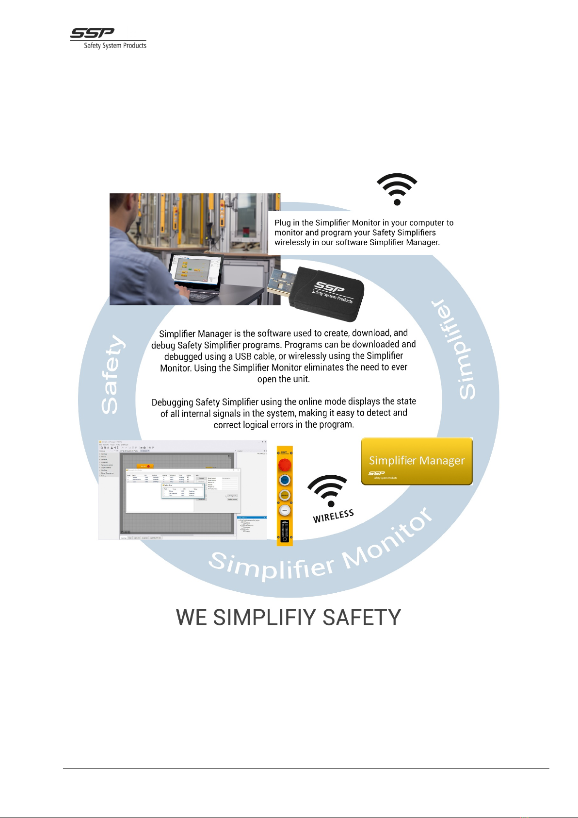
The configuration software Simplifier Manager is used for:
- Programming and compiling logic that can be run on Safety Simplifier
systems
- Configuring Safety Simplifier devices as systems
- Monitoring and debugging Safety Simplifier systems
- Generating documentation about Safety Simplifier system
Configuration of Safety Simplifier devices is performed either via USB using the micro USB connector
inside the Safety Simplifier, or wirelessly using Simplifier Monitor.
Figure
2.2 Example of a Simplifier system of four units, using a
combination of CAN and radio to communicate.
Figure
2.1 The Simplifier system as part of an EUC

SSP North AB 30/08/2018 Manual V2f
14
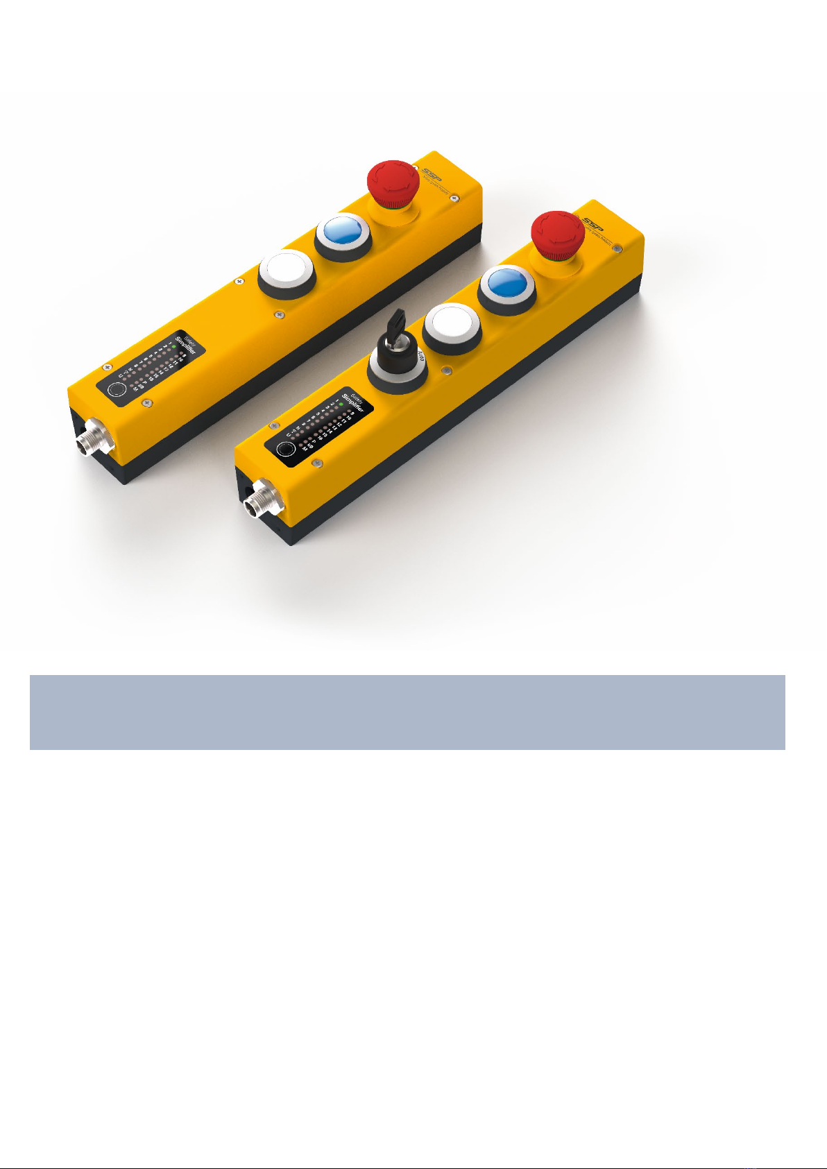
2.1 Features
- Up to 14 transistor I/O configurable as inputs or outputs (or as a combination of both)
- Up to 2x2 doubled relay outputs
- An optional LED display for failure codes and status information
- 2.4 GHz radio and/or CAN-bus for safety communication between up to 16 units
- Spring terminals for I/O connections
- IP 65 housing
- Two openings on each short side for M12- contacts or cable glands M16
- Optional opening for PB: s, selectors, E-stop etc
- USB and/or radio communication for Simplifier Manager
2.1.1 Example input functions
- Emergency stop switches
- Two hand stations according to EN 574
- Safety gate limit switches
- Reset devices
- Light beam devices
- Light curtain devices
- Scanners
- Enabling switches
- Hold to run device
- Operating mode selector devices
- Safety mats and strips
- RFID-sensors
- NC contacts for supervising of relays controlled from outputs
- Eight coded signals (four regular, four inverted) from the same unit
- Two coded signals (one regular and one inverted) from other units
- Voltage window and inverted voltage window
- Specific voltage comparator
2.1.2 Example Output Functions
- 10 - 30 VDC outputs for machines
- 10 - 30 VDC OSSD outputs with short circuit detection between up to 14 outputs
- 10 - 30 VDC for 8 safety coded signal within one Safety Simplifier
- 10 - 30 VDC for 2 safety coded signals between Safety Simplifiers
2.1.3 Combined I/O
Combined I/O are I/O that can be used as safe inputs and non-safe outputs at the same time.
- Reset pushbuttons with lamp indication
- Start and stop push buttons with lamp indication
- Other devices or push buttons with lamp indication

SSP North AB 30/08/2018 Manual V2f
15
2.1.4 Redundant Relay Outputs
Two optional potential free redundant relay outputs for safety.
The relay outputs can for example be used for:
- Safety inputs on Irb:s and other machines
- The control of door locking devices and other safety mechanisms
2.1.5 I/O outputs for “non-safety” information
All transistor I/O:s can be used for non-safety as for example:
- Serial information for up to 32 internal signals from logic. This can be used between two
different Safety Simplifier systems or between Safety Simplifier units and other PLCs to
exchange non-safety information without the need of a common application program.
- Indication and status information
All relay outputs can be used for non-safety as for example:
- Indication and status information
2.1.6 LED information
See chapter 11.9 The LED display menu on page 39 for a detailed description of how the LED display
menu is operated.
The LED-information on a Safety Simplifier shows:
- Node number and number of nodes in a system
- I/O status on actual node and other nodes in a system
- Supply voltage level for actual node and other nodes in a system
- Global Memory status on actual node and other nodes in a system
- Radio channel and communication status on actual node and other nodes in a system
- Indication of nodes with CAN communication and CAN memory status and on actual node and
other nodes in a system
- Error codes
- I/O errors

SSP North AB 30/08/2018 Manual V2f
16
3 Safety Precautions when using Safety Simplifier
Warning!
Read this information carefully as it is essential information on how to design and
use the Safety Simplifier System in a safe way.
The Safety Simplifier system has three modes of operation:
1. Normal mode: The Safety Simplifier PLC controls the outputs according to inputs and logic.
2. Safe state: a state during which outputs are in safe state.
3. PLC Configuration mode. The Safety Simplifier is off-line, and all outputs are in safe state.
This is the only mode where a new configuration can be downloaded from a PC.
Safe state is defined as a state when outputs are turned off (goes low = 0V) and the output relays are
deenergised (all contacts open).
In a system of more than one Safety Simplifier, if a node loses communication from another node, it
will consider all the safety information from that node as 0 (off, open, deenergised). It is important to
design the system so that loss of communication results in the relevant outputs turning off (0V).
If an internal dangerous failure is detected the affected Safety Simplifier unit goes to safe state. The
safety communication via radio and CAN-bus is turned off. The other nodes in the system will lose
connection to the affected Safety Simplifier unit and all safety information from that unit are set to 0.
Information on the cause of the dangerous failure is available on the LED-panel and via USB on the
actual unit. Information is not available wirelessly via radio or via CAN as this communication is shut
off.
If an external dangerous failure is detected (such as a short circuit on an OSSD output or an input that
detects an invalid coded signal), the affected inputs and/or outputs turn off. The error information is
available on the LED-panel, wirelessly, via CAN and USB, and as an internal signal in logic. If more
actions are required, the logic can be programmed to set the device in safe state, turn off other
functions, or perform other actions, in case an input or output function detects an external error. This
choice must be taken by the system integrator.
The system is designed for applications where; 0V, open circuit, logic “0”, low signal, loss of radio
signal, loss of bus communication etc generates a safe state (stop/off). The application must be
designed according to the “de-energisation” principle, meaning that stop functions shall operate by de-
energizing as well as with safe state conditions.
Safe state = “0”. A fault in the system can set inputs, outputs, memories etc. to logic “0” which is
regarded as a safe state. Logic “1” must therefore normally not be used to generate a safe state
(stop/off). An exception is a dual or multiple channel function with logic “1” combined with logic “0”.
28It is essential that loss of radio communication and CAN-bus communication lead to safe state. This
must the principle when programming a system with two or more Safety Simplifiers communicating
between each other through radio or CAN-bus.
For control devices which starts a function when they are actuated it is important to use the start-up
function for the inputs connected to the devices and to use the start-up function for global and CAN
memories used between Safety Simplifiers. The start-up function requires a control device to be
released and activated again after loss of power, loss of communication and loss of one or more input
signals.

SSP North AB 30/08/2018 Manual V2f
17
In a safety system using two or more Safety Simplifiers it is important that it is planned how to handle
a loss and return of communication. If a Safety Simplifier loses communication signals only those
functions depending on the signals/memories in the communication will react. All other functions will
continue to work. When the communication comes back after a loss it is up to the programmer of the
system to decide the actions. The programmer can for example require every function to stop if one or
more Safety Simplifiers loses communication. The programmer can also select to require a restart
after return of communication. This must be decided by the risk analysis for the system.
The Safety Simplifier System offers a set of function blocks intended for different safety functions such
as two-hand, monitoring of dual channel input, dual OSSD outputs etc. It is strongly recommended
that these function blocks, which are checked and certified, are being used. See the software part of
this manual for more information.
All logic for safety shall be designed in such a way that no hazardous conditions are caused if a unit or
outputs goes to safe state.
The Safety Simplifier unit/s shall be restarted at least once per year to fulfil the safety requirements. If
the application where it is used requires restarts more often than that, that requirement shall be
fulfilled.
All programming, logics and connections for safety shall be done in accordance to the manuals for
Safety Simplifier and to the actual safety requirements and legislation for the EUC.
To identify a Safety Simplifier each one has a unique serial number (32 bits) for the identification. The
software for a system of 2 – 16 Safety Simplifier also has a network id based on all the Safety
Simplifiers serial number in a system to have a safe communication.
Each Safety Simplifier must have the same firmware to communicate (se Safety Simplifier Manual).
Every application program for Safety Simplifier has a unique code to verify the right program. Any
change in a program will change the code.
Since Safety Simplifier is a system for the control of safety functions it is vital that personnel involved
in design, programming and maintenance have sufficient knowledge about the system and knowledge
in the field of machinery safety for the actual machinery. It is also important that the safety system is
carefully tested and documented.
Reprogramming of an existing program can be necessary, and this can be carried out a long time after
the original programming was done. It is then important that the programmer is familiar with the
system, the hardware application, the program code and is sure about the intention with the revision. It
is also important that the modification is carefully tested and documented.
Download of application programs shall be password protected and this can be set in Simplifier
Manager. The intention is that the password is kept in secret by a responsible person who gives
permission for revision of programs. If the password gets commonly known, it should be changed.
The most important part before a machine or other safety application is taken in use is to verify correct
behaviour according to the specification and the risk analysis by testing all the safety functions in the
safety system. Since many design faults are difficult to find only by a practical test it is also necessary
to make a review of drawings and PLC program. It is recommended that tests and verifications also
are done by person/s other than the designer. This is one way to prevent faults in design and
systematic failures.

SSP North AB 30/08/2018 Manual V2f
18
The safety Simplifier shall only be used in an environment which is in line with the environment
conditions stated in the technical data.
The Safety Simplifier has I/O and logic signals for safety and for non-safety.
The safety functions are monitored and controlled by both processors.
The non-safety is optimised for non-safety functions and flexibility. These shall not be used for safety
as they are not controlled and monitored by both processors. Examples of this is the information
communication between Safety Simplifiers, via the Simplifier Monitor to a computer as well as the
information on the LED-display.
In the programming software Simplifier Manager, all non-safety signals are indicated by a dotted white
line, while safety signals are coloured solid yellow. Non-safety function blocks are coloured grey.
The safety functions in a Safety Simplifier are for example:
- Up to 2x2 double relay outputs
- Up to 14 I/O selectable as input, output or a combination
- Detection of voltage level from 0 – 30 VDC
- Pulsed output signals
- Distinguishing between different pulsed input signals
- Short circuit detection on inputs and outputs
- Detection of ON and OFF conditions for inputs and outputs
- Up to 14 OSSD outputs with short circuit detection
- 16 Global memories for radio and CAN-buss communication
- 16 extra CAN-memories on CAN-buss

SSP North AB 30/08/2018 Manual V2f
19
3.1 Safety information regarding I/O and relay outputs of Safety
Simplifier
3.1.1 The relay outputs
Two optional, potential free, doubled safety relay outputs can be used to control safety
functions up to SIL 3/PLe/cat 4.
A relay output consists of two separate relays each having one NO contact connected to terminals.
Each relay is controlled and supervised by a processor. The processors compare the result with each
other. The processors check that the contact in each relay is opened every time a relay is
deenergised. The output 15 (terminal 23-24 and 33-34) control a safety function up to SIL 3, PLe cat 4.
Output 16 (terminal 43-44 and 53-54) has the same function.
Caution!
Both output contacts from 15 respectively from 16 must be used in a safety function
to achieve a redundant safety output of category 3 or 4.
A relay output cannot check if there is a short circuit over a contact in for example a
cable. Short circuit detection needs to be performed at the device connected to the
relay output contacts.
For relays the number of operations and braking capacity have an impact on the
PFH-d value. For low number of operations as for E-stop a higher current can be
switched by the relays during its lifetime. For high numbers of operations, the
switched current should be lower. See chapter 4 Technical data Safety Simplifier
(page 23) and chapter 9 Calculating PFH-d values (page 32).
SSP North AB 30/08/2018 Manual V2f
20
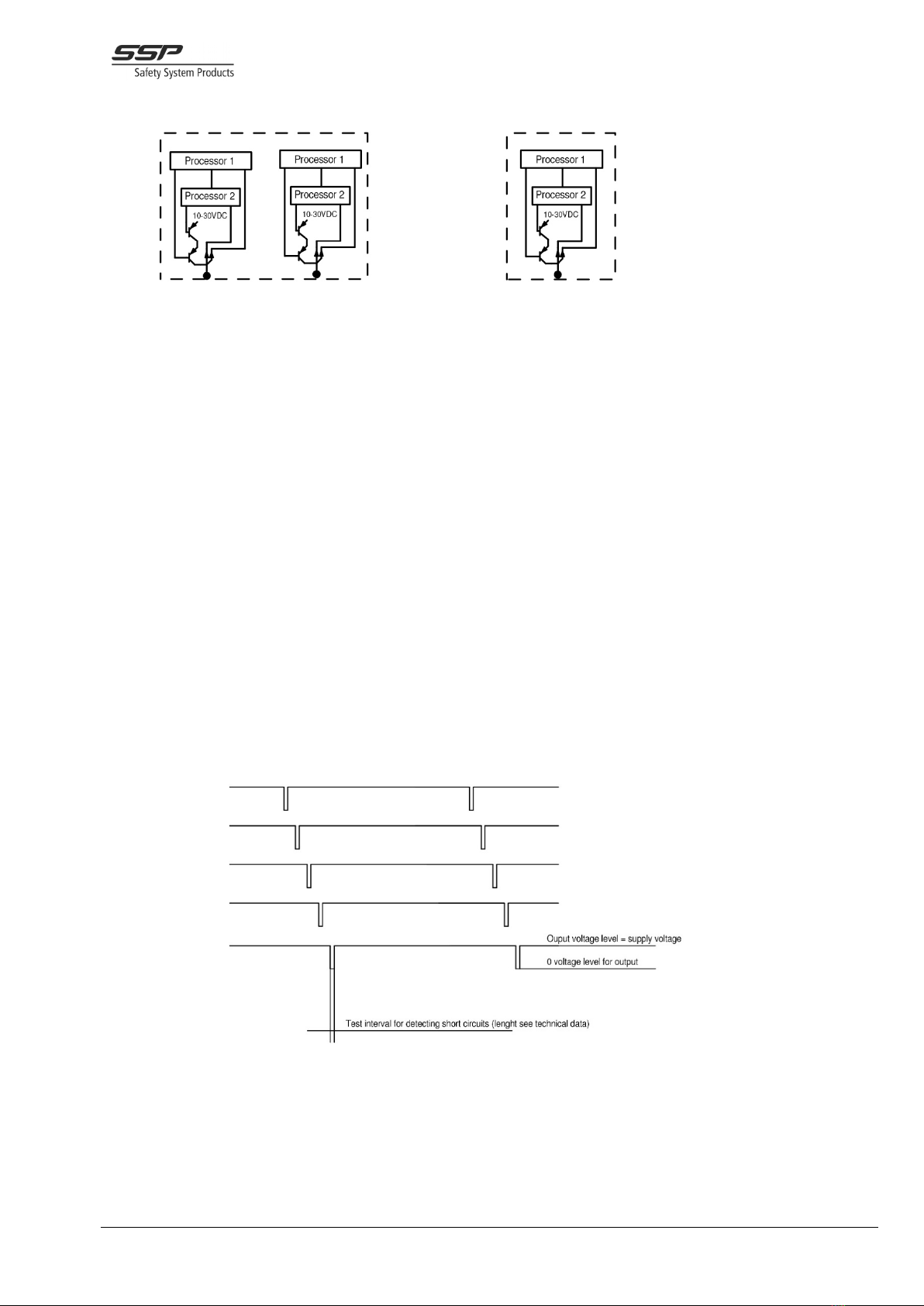
3.1.2 Solid-state transistor outputs
Up to SIL 3, Ple, Cat 4 redundant output Up to SIL 3, Pld, Cat 4 redundant output
Each output has two transistors in series and each one is controlled by each processor. Each output is
therefore a redundant output up to a certain degree, (see PFH-d values and a note below). Both
processors are also checking the signal transmitted from the output. This way both CPU:s check the
actual voltage level and coded signals sent out from the output. A single output which detects an
external short circuit can turn of itself but not the external short circuit. We recommend double static
outputs for SIL3, Ple, cat 4.
Any of the 14 I/O can be set in the Simplifier Manager to different output types in ON and OFF state.
The selectable output types for an I/O are:
1. VDC/+V (maximum 0.5V less than supply voltage)
2. 0 VDC
3. OSSD = output voltage level is 0,5 V less than supply voltage and this type of output also
detects a short circuit to other OSSD outputs in the same unit and to internal and external
fixed voltages. If there is an external short circuit the relevant outputs will be shut off, set to
OFF state or to fatal error depending on the type of short circuit and on how the application
program is done. See the Safety Manager manual for more information. The check of the
output is done during a very short time (less than 150 micro seconds) when the voltage level
shall go down to 0V. The OSSD outputs are commonly used in the industry in safety devices
and for stop signals to machines. Up to 14 OSSD output can be selected in a Safety Simplifier.
Drawing shows 5 OSSD outputs with short circuit detection. Up to 14 OSSD outputs can be selected
from a Safety Simplifier. A short circuit between any of these or to external voltage, is detected as an
external fault. A short circuit to one or more outputs will set the output to 0 volt. Other outputs it the
same function block will be set to OFF state. The fault will be indicated on the LED panel.
The test interval is very short (below 150 micro seconds). A conductor or a relay connected to an
OSSD output will normally not fall during this time. See technical data for test interval specification.
Table of contents
Other SSP Safety Equipment manuals


Popular Safety Equipment manuals by other brands

WaterWarden
WaterWarden SmartPool Pool Safety Net Installation & maintenance manual

Mini Gadgets
Mini Gadgets BB2ElectricalBox user manual

Dräger
Dräger SPC 4800 Instructions for use

TEUFELBERGER
TEUFELBERGER treeMOTION MANUFACTURER'S INFORMATION AND USER INSTRUCTIONS

Guardian Fall Protection
Guardian Fall Protection 15026 instruction manual

GTS
GTS I-9201 manual


(12) instruction manual")


