SSS Siedle ACHIEVER 80 Installation and operation manual

OPERATING & MAINTENANCE
INTRODUCTION INSTRUCTIONS
READ THIS BOOK
Self-Contained Carpet Extractor
ACHIEVER 80
ACHIEVER 110
This operator’s book has important information for the use
and safe operation of this machine. Read this book care-
fully before starting the machine. Keep this book and tell
all operators to read the book. If you do not follow the
instructions, you can cause an injury or damage equipment,
furniture or buildings.
For additional information refer to the Triple S website
www.triple-s.com or write to:
Triple S
2 Executive Park Drive
Billerica, MA 01862
Carefully inspect all components to ensure that there is no
concealed freight damage. If such damage is discovered,
file a “CONCEALED DAMAGE REPORT” immediately
with the delivering carrier.
The contents of this manual are based on the latest product
information available at the time of publication. Triple S
reserves the right to make changes or improvements to its
machines without notice.
FOR YOUR CONVENIENCE, RECORD THIS
IMPORTANT INFORMATION:
MODEL_______________________________
SERIAL NUMBER______________________
PART NUMBER ________________________
DATE PURCHASED ____________________

INTRODUCTION
The SSS ACHIEVER Machine is a fully self-contained, portable carpet extractor system and is intended for commercial use.
A wand with external vacuum and solution hoses are not necessary with your ACHIEVER machine, but available.
The ACHIEVER 80/110 has a 100 psi solution pump and a four (4)jet spraying system located on the bottom side of the ma-
chine to apply solution to the carpet.
A rotating brush is driven by a cogged belt system at approximately 1200 RPM’s. This brush provides a very aggressive agita-
tion of the solution into the carpet fibers to loosen ground-in dirt. The chevron pattern of the brush bristles channels the dirty
water to the center of the aluminum vacuum head for better extraction.
With a heavy duty three-stage vacuum motor, capable of 137 inches of water lift, your ACHIEVER machine extracts virtually
all of the dirty solution from the carpet fibers, which dramatically reduces drying time.
The ACHIEVER 80/110 machines are very “user friendly” machines. All controls are located at the top of the handle grips,
literally at your fingertips. The recovery tank drain valve is located high enough for the recovered solution to be drained into a
five (5) gallon bucket or bathroom toilet.
ACHIEVER 80/110 machines are balanced on large 10″ diameter wheels for ease of operation and transporting. The machines
can be rotated 360° with relative ease, even when filled with solution.
The location of the wheel axle and the large diameter wheels allows for easy transporting up and down steps when
empty. It is not recommended these machines be transported up or down steps while containing any liquid in either the
solution or recovery tanks.
This machine must be grounded. If it should malfunction or break down,
grounding provides a path of least resistance for electric current to reduce
the risk of electric shock. This machine is equipped with a cord having an
equipment-grounding conductor and grounding plug. The plug must be
inserted into an appropriate outlet that is properly installed and grounded
in accordance with all local codes and ordinances.
WARNING - Improper connection of the equipment-grounding conductor
can result in a risk of electric shock. Check with a qualified electrician
or service person if you are in doubt as to whether the outlet is properly
grounded. Do not modify the plug provided with the machine - if it will not
fit the outlet, have a proper outlet installed by a qualified electrician.
This machine is for use on a nominal 120-volt circuit, and has a grounded
plug that looks like the plug illustrated in figure A. A temporary adapter
that looks like the adapter illustrated in figures B and C may be used to
connect this plug to a 2-pole receptacle as shown in figure B if a properly
grounded outlet is not available. The temporary adapter should be used only
until a properly grounded outlet (figure A) can be installed by a qualified
electrician. The green colored rigid ear, lug, or the like extending from
the adapter must be connected to a permanent ground such as a properly
grounded outlet box cover. Whenever the adapter is used, it must be held
in place by a metal screw.
NOTE: In Canada, the use of a temporary adapter is not permitted by the
Canadian Electrical Code
EXTENSION CORDS
Use only three-wire 14/3 or larger gauge approved extension cords that have
three-prong grounding type plugs and three-pole receptacles that accept the
appliance’s plug. Replace or repair any damaged cords or plugs.
When servicing, refer to authorized person only. Use only identical
replacement parts.
Grounding Instructions
2
NOTE: Do not use adapters shown in figures B & C in Canada

When using an electrical appliance, basic precautions should always be followed, including the following:
READ ALL INSTRUCTIONS BEFORE USING THIS MACHINE
WARNING: To reduce the risk of fire, electric shock, or injury:
1. You must have training in the operation of this machine before using it.
2. Machines can cause an explosion when near flammable materials and vapors. Do not use this machine with or near fuels,
grain dust, solvents, thinners, or other flammable materials.
3. Do not operate this machine unless it is completely assembled.
4. Do not use this unit for dry pick-up of dust or debris.
5. To prevent electric shock, always remove the electrical plug from the electrical outlet before doing any repairs or mainte-
nance to this machine.
6. To prevent injury, always remove the electrical plug from the electrical outlet before leaving the machine.
7. Maintenance and repairs must be done by authorized personnel only.
8. Do not immerse. To reduce the risk of electrical shock, use only on carpet moistened by the cleaning process. Protect the
machine from rain. Keep the machine in a dry building. Always clean the machine with a clean dry cloth.
9. Always use a three-wire electrical system connected to the electrical ground. For maximum protection against electrical
shock, use a circuit that is protected by a ground fault circuit interrupter. Consult your electrical contractor.
10. To prevent damage to the power cord, do not move this machine over the power cord. Always lift the power cord over the
machine. Do not pull or carry cord, use cord as a handle, close a door on cord, or pull cord around sharp edges or corners.
Keep cord away from heated surfaces.
11. Make sure all switches are turned off before plugging or unplugging it power cord into/from a wall receptacle.
12. Do not use water that is hotter than 60°C (140°F).
13. To prevent damage to the solution system components do not store in freezing temperatures without proper maintenance.
14. Do not allow to be used as a toy. Close attention is necessary when used near children.
15. Do not use with damaged cord or plug. If the machine is not working as it should, has been dropped, damaged, left outdoors,
or dropped into water, return it to a service center.
16. Do not unplug by pulling on cord. To unplug, grasp the plug, not the cord.
17. Do not handle the plug or machine with wet hands.
18. Do not put any object into openings. Do not use with any opening blocked. Keep free of dust, lint, hair and anything that
may reduce the airflow.
19. Keep hair, loose clothing, fingers and all parts of body away from openings and moving parts.
20. Do not pick up anything that is burning or smoking, such as cigarettes, matches or hot ashes.
21. Use extra care when cleaning on stairs.
SAVE THESE INSTRUCTIONS
IMPORTANT SAFETY INSTRUCTIONS

4
PREPARATION AND TRANSPORTATION
PRESTART-UP CHECKS
ACHIEVER 80/110 machines are very simple and easy to
operate. Very little maintenance and service are required to
keep your machine in top operating condition.
The following procedures are recommended to maintain
the high level of performance expected from your machine.
They are also intended to identify potential safety hazards
and problems which could reduce the service life of the
machine.
READ BEFORE TRANSPORTING OR OPERATING
YOUR MACHINE:
1. Check power cord, plug and strain relief for worn or
damaged insulation. Repair or replace if necessary.
2. Make sure the drain valve is closed (T-Handle pushed
down). If the valve is left open, the vacuum is dra-
matically reduced and any recovered solution will drain
out.
3. The knob for the spool valve is located on the lower
back panel of the machine. During normal operation
as a self-contained extractor this knob is turned toward
“machine” (horizontal position). It should be turned
to the “tool” position (vertical) when a wand or other
tool is being used.1.
4. Lock the brush chassis in the up position for storage or
transport. This is done by pulling up on the lift-handle
at the front of the machine, then resting the round lift
stop behind the bracket.
5. Inspect the vacuum head and brush by tilting the ma-
chine backwards, allowing it to balance on the wheels
and drain valve spout.
a) Vacuum Head: Check for any damage. Burrs on
the contact surface may snag carpet fibers. Gouges,
scratches and chipped areas can reduce vacuum
performance.
b) Brush: Inspect for damaged or missing bristles,
replace if necessary.
Return the machine to the upright position.
6. Check the inlet strainer for damage or debris. It is
located at the bottom of the fresh water tank. Holes in
the screen can allow contaminants to enter the pump
resulting in costly repairs. A clogged strainer will
reduce pump performance and may cause permanent
damage.
7. Remove the clear dome on top of the recovery tank.
a) Inspect for damage to the dome and gasket.
Dirt or debris on the gasket or sealing surface
of the tank can cause a vacuum leak and reduce
vacuum performance.
b) The intake filter screen at the vacuum hose
connection should be clean of debris and
checked periodically for any damage, replace
if necessary.
c) Ensure that the deflector shield and intake
filter are in their proper positions to prevent
recovered water from entering the vacuum
motor (blower).
Return the cover to its original position with the front
lip seated under the retaining bracket.
YOUR MACHINE IS NOW READY FOR OPERATION.
TRANSPORTING
The ACHIEVER 80/110 is equipped with large diameter
(10″) wheels for balance and ease of transporting. It is de-
signed to be tilted back on the wheels and pushed or pulled.
The brush chassis should be locked in the up position any
time the machine is in storage or being transported.
The large diameter of the wheels permits you to pull the
machine up stairs in the same manner you would use a
hand truck. Never go up or down stairs with recovered
water or solution in the tanks. Always empty the machine
completely before transporting up or down stairs or in a
vehicle.
When empty, the machine may be laid down on the side for
transporting without damaging any of its components.

5
OPERATING PROCEDURES
The ACHIEVER 80/110 machines are the most “user
friendly” self-contained extractors available. The following
procedures are intended to describe and detail proper opera-
tion of your machine. Failure to follow these recommended
procedures can reduce the machine’s performance and may
result in damage to the machine.
1. Vacuum the area to be cleaned. Your machine will
do a more thorough job if the loose dirt and debris are
removed before the extraction process begins.
2. Fill the fresh water tank (lower tank) with water and
Heavy Duty Carpet Extraction chemical. Hot water is
recommended, but not required. Do not use water hotter
than 60°C (140°F). Mix in chemicals according to the
chemical manufacturer’s recommendations. For best
results use Steamex Heavy Duty Carpet Cleaner.
3. Use of an extension cord is not recommended. How-
ever, if one is necessary, use only a 14 gauge or larger
cord. Smaller or inferior cords are dangerous and may
cause damage to your machine.
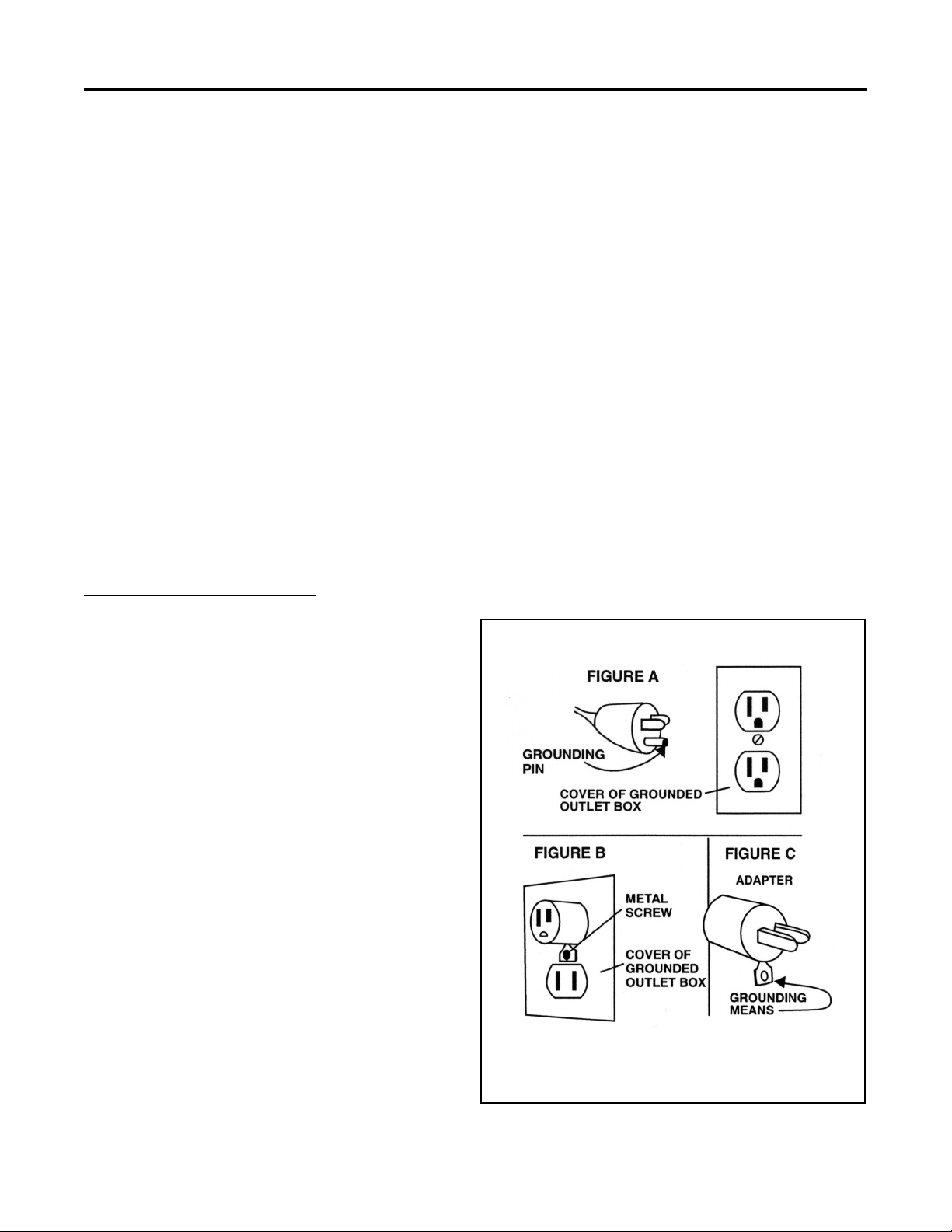
4. After the machine is filled with solution, connect the
power cord plug to a 115 volt grounded wall socket.
See Grounding Instructions.
5. Lower the floating brush chassis using the lift handle
located in the front of the machine. Lift the handle off
the lift stop bracket and lower until the brush contacts
the floor. Remember to always raise and lock the brush
chassis for storage and transport.
6. Turn the spool valve knob (located on the back of the
machine) to the:
a) “Machine” (horizontal) position for routine
carpet extraction as a self-contained unit, or
b) Turn it in the “Tool” (vertical) position when using
a wand or tool.
7. The switch panel is located on top of the handle and
contains the following:
a) Turn the vacuum switch on to start the vacuum
motor.
b) Accessory only pump switch: Do not turn on the
accessory pump switch unless the spool valve knob
is turned to the tool position.
8. Pull backward during operation. DO NOT AT-
TEMPT TO OPERATE IN A FORWARD DIREC-
TION. Position yourself behind the machine, grasp
the handle and gently lift up on the actuator bar.
Lifting the actuator bar activates the brush drive motor
and the pump. Walk slowly backward to perform the
cleaning process.
9. Release the actuator bar approximately 6 inches
before completing each pass. The spray jets are
located behind the vacuum head making it necessary
to pull the machine a few inches further to pick up the
last amount of solution dispensed onto the carpet.
10. Tilt the machine back on the rear wheels and walk
forward to position the machine along side the previ-
ous pass (slightly overlapping).
11. As dirty solution is recovered, some foaming may be
noted. Excessive foaming can be counteracted with
liquid defoamer applied according to the chemical
manufacturing directions. Do not allow foam to rise
into or near the dome. Use defoamer or empty and
flush the recovery tank.
12. To drain the recovery tank, place an empty bucket
under the drain valve located on back of the machine.
To open the drain valve pull the T-Handle up. Close
the drain when the bucket is full or the recovery tank
is empty. Dispose of the recovered water properly.
13. If streaking occurs after a period of operating time,
this means the solution (fresh water) tank is near
empty. Streaking is eliminated by adding more water
and chemical solution to the tank.
14. To drain the solution tank, attach the small drain or
“pump out” hose to the accessory quick connect on
the back of the machine. Turn the spool valve knob
to the “tool” position. Place the open end of the hose
into a bucket and turn on the accessory pump switch.
When empty, turn off the pump switch and remove
the hose from the quick connect. Also return the spool
valve knob to the “machine” position.
15. After each use clean the dome, intake filter and
gasket. Do not reinstall the dome until the next use,
this will allow the recovery tank to dry out.
16. Raise the brush chassis for storage.

6
SERVICING
ACHIEVER self-contained extractors are designed and manufactured to provide years of trouble free service with a minimum
of maintenance and service. The following recommendations are intended to assist the operator and Service Technician in
performing routine maintenance.
Failure to follow these recommendations can result in damage to your machine and diminished performance.
Warning: Always unplug your machine before performing any service. Severe personal injury could result if the elec-
trical power is not disconnected.
1. Always follow through with the recommended prestart-
up checks found in the Preparation and Transportation
section of this manual.
2. Store your machine in a dry, protected area with the
brush chassis raised and locked in place. Do not ex-
pose this machine to rain, standing water or freezing
temperatures.
3. We recommend a good, thorough cleaning after each
use. Clean the dome top, intake filter screen and recov-
ery tank with fresh, clean water. Flush the fresh water
tank and strainer periodically with clean water.
4. After continuous or repeated use, the jet tips and
strainer/check valves will need cleaning. Unplug the
cord and empty the recovery and solution tanks. Tilt the
machine backward allowing it to balance on the wheels
and drain valve. Remove the jet caps shown in the brush
chassis illustration and clean with white vinegar and a
soft bristle brush. Remove the jet tip and strainer/check
valve and soak it in vinegar until visible deposits are
dissolved, then scrub with a soft bristle brush.
Jet tips and strainer/check valves should be replaced
once a year because they tend to erode under ex-
tended use. This can cause overuse of solution and
possible streaking.
AN AUTHORIZED SERVICE CENTER SHOULD PERFORM THE FOLLOWING PROCEDURES
1. Drive Belt Adjustment and/or Replacement: The
cogged drive belt system rarely needs tightening, so
if it becomes loose from wear, it is time to replace it.
Follow this procedure:
a) Remove the two screws that attach the hanger
bracket to the brush shroud. Then remove the
thru-bolt from the brush chassis and lift handle.
Remove the lift handle and lift stop.
b) Tilt the machine backward allowing it to balance
on the wheels and drain valve. The brush chassis
will remain on the floor exposing the brush drive
belt and motor.
c) Loosen the two motor bracket mounting bracket
mounting bolts with a 7/16″ wrench. DO NOT
REMOVE THE BOLTS UNLESS YOU ARE
REPLACING THE MOTOR. Slide the motor
away from the brush to tighten the belt or toward
the brush for removal.
Unlike a “V” type belt, the cogged belt is run with basically
zero deflection. To test the belt tension, hold the belt between
your thumb and forefinger and twist to the side. It should
turn approximately 90° with little effort. If it twists more
than 90°, retighten the belt.
2. Pump Replacement:
a) Remove the lift stop handle as described in the
“Belt Drive” procedure (#1a).
b) Tilt the machine backward as described in the “Belt
Drive” procedure (#1b)
c) Disconnect black wire (#2) and the white wire
from the bridge rectifier (part #A130172). Also
disconnect the ground wire (this will need to be
respliced and reconnected to the ground wire on
the brush motor when reassembling). Reference
the electrical schematic.
d) Remove the two hoses from the pump. It is now
fully exposed for replacement.
e) When reassembling after any repairs, make certain
that all wire connections are properly plugged in
and secure.
f) Make all solution hose connections secure.

7
3. Vacuum Blower Replacement:
a) Remove the dome top and carefully turn the ma-
chine upside down.
b) Remove the two hex bolts at the base of the black
panel on the back of machine.
c) Remove the wheels in order to get at the hex bolts
in step (d). Shoulder bolts hold the wheels on.
d) Then remove the six hex head bolts on both sides
of blower chassis.
e) Disconnect the two power leads and the ground
wire coming through the back of the machine to
the blower.
f) Tip the blower and brush chassis away from the
machine and carefully feed the vacuum hose down
through the back of the machine.
g) Then remove the three (3) bolts that hold the bracket
for the blower. Remove the bracket.
h) Release the blower from the bracket by removing the
three bolts which hold them together.
i) The blower can now be removed.
j) When reassembling after any repairs, make certain
that all wire connections are properly plugged in and
secure.
k) Avoid abrasive contact with sharp edges on the metal
parts as injury can result.
l) Make sure all vacuum hose connections are secure.
WIRING DIAGRAM

TANK & BLOWER
8

TANK & BLOWER
ITEM PART NO. DESCRIPTION QTY. ITEM PART NO. DESCRIPTION QTY.
1 208662 Recovery Tank 110 1 41 W317D Screw #4-40 x 1-1/4” PHP MS SS 2
208661 Recovery Tank 80 1 42 3703 Switch - Momentary 2
2 W191D1 Screw #10-24 x 3/4 RHP SS 2 43 W307D Washer #4 Ext Tooth 2
3 217201 Dome Clasp 1 44 W385D Nut: #4-40 Hex w/Nyloc 2
4 W106D Nut #10-24 Hex SS 3 45 3675 Switch Plate 1
5 215005 Dome Assembly w/Gasket 1 46 980015 Washer #10 Ext Tooth 1
6 212704 Dome Assembly w/o Gasket 1 47 3716 Sleeve: Wiring 6”
7 213405 Dome Gasket 1 48 3799 Actuator Bar 1
8 3685 Intake Filter (3732 Scr.; 3733 PVC) 1 49 3686 Switch Enclosure 1
9 A12999 Lift Stop 1 50 3710 Grommet 2
10 A12998 Lift Handle 1 51 C12995 Chassis 1
11 D161C Decal: Add Defoamer 1 53 W169D Screw 1/4-20 x 1/2” HH CS SS 15
12 3698 Cuff Hose 2 54 W104D Washer 1/4” Flat SS 9
13 3694 Hose 1 1/2 “ x 33” (part of 3691) 1 55 980005 Washer 1/2” Wave 2
14 3735 Cuff Hose 1 56 229750 Wheel 2
15 3695 Hose 1 1/2” x 62” 1 57 509820 Washer: Fibre 2
16 S611A Hose Clamp 1 58 960031 Shoulder Bolt 2
17 S216P Hose Clamp 2 59 A129671 Hinge 1
18 A13007 Adaptor 90° 110 1 60 W363D Pop Rivet 7
A13005 Adaptor Straight 80 1 61 C12996 Bracket: Blower Mounting 1
19 A13122 Drain Hose 1 1/4” x 1.25’ 1 62 W362D Bolt 1/4-20 x 4 1/2” HH 3
20 A13006 Adaptor: Reducing 1 63 603473 Gasket Blower (effective 11/00) 1
21 S102P Thru the Hull Fitting w/Gasket & Nut 1 64 A13504 Blower 3-Stage 115V - 110 1
22 930008 Pop Rivet 5 215201 Blower 2-Stage 115V - 80 (eff.01/01) 1
23 S400P6 0 Ring 1 S818N Grounding Terminal for 215201
24 S400PB Drain Valve 1 S589P Blower 2-Stage 230V - 80 1
S400P2 Drain Valve Seal Kit 1 3738 Blower 3-Stage 230V - 110 1
S400P3 T-Handle 1 65 210901 Carbon Brush for A13504 Motor 2
25 S400PB4 Drain Elbow 2” 1 210906 Carbon Brush for 215201 Motor 2
26 W189D Screw 1/4-20 x 3/4 HH CS SS 10 210904 Carbon Brush for all 230V 2
27 980002 Lockwasher Split 1/4” 24 66 920004 Nut 1/4-20 Hex SS 7
28 W212D Washer 5/16” Fender Zinc 2 67 W311D Washer 1/4” Fender 6
29 208660 Main Body - Grey 1 68 213403 Gasket: Lift Bracket (S791N1) 1
208663 Main Body - Black 1 69 A13439 Bracket: Vac Head 1
30 3687 Back Plate 1 70 C13118 Shroud 1
31 3739 Snap Bushing 2 71 C13382 Head: Vacuum 1
32 D167C Decal: Warning Disconnect 1 72 B13000 Lift Bar 2
34 908073 Power Cord 50’ 1 73 B13126 Hanger Bracket 1
35 A13020 Strain Relief 1 74 920011 Nut 1/4-20 Nyloc 3
36 911089 Switch Rocker 2 75 W340D Screw 1/4-20 x 3 3/4 HH SC 1
37 W136D1 Screw #8 x 1/2” THP SMS B/O 6 77 980004 Washer 1/4” Flat 6
38 W387D Screw #8-32 x 3/8 RHP M/S B/O 4 78 S209P Hose: Exhaust 6” 1
39 980026 Washer #8 Int. Tooth 5 79 920616 Nut 1/2 NPT 1
40 W143D Nut: Hex #8-32 SS 4

10
WATER CARRYING AND BRUSH CHASSIS

11
WATER CARRYING AND BRUSH CHASSIS
Achiever 80 & 110
ITEM PART NO. DESCRIPTION QTY. ITEM PART NO. DESCRIPTION QTY.
1 S626P Strainer 1 27 211501 Jet Cap 4
2 W166D Brass: Jam Nut 5 28 W205D Screw #8-32 x 1” Nylon M/S 1
3 S372P Washer: Nylon 1 29 A13445 Rectifier 1
4 211310 90° Jet Body 3/8 2 30 920617 Nut #8-32 Hex Nylon 2
5 203308 Quick connect 1/4 Female 1 31 A13017 Motor: Brush Drive 115V 1
6 920620 Nut, .875 Stud 1 3760 Motor: Brush Drive 220V 1
7 3770 Elbow: Barb 1/8 to 3/8 2 32 200870 Bracket: Brush Motor 1
8 202050 Clamp: Hose 14 33 W124D Washer: Lock #10 Int Tooth 2
9 S250P Hose (Order 6”) 2 34 W329D Nut #10-32 Hex 2
10 3766 Tee: Barb 3/8 Nylon 1 35 3719 Cog: Drive Motor 1
11 A13151 Knob 1 36 3723 Belt: Drive Brush 1
12 3824 Spool Valve w/Knob 1 37 7560 Brush Assembly 1
13 3771 Elbow: Barb 1/4 to 3/8 1 38 962062 Screw #6 x 3/4” SMS 4
14 S250P Hose (Order 36”) 1 39 3718 Cog: Brush 1
15 S250P Hose (Order 36”) 1 40 3677 Bearing: Rulon 1
16 S250P Hose (Order 36”) 1 41 3722 Insert: Drive Brush 1
17 S250P Hose (Order 6”) 3 42 3689 Brush 1
18 3785V Pump: 100 PSI 115V 1 43 3721 Insert: End Brush 1
3821V Pump: 100 PSI 220V 1 44 A13084 Bearing: Rulon 1
18A 204557 Pump Head Complete 1 45 A12954 Brush Shaft 1
18B 911112 Kit: Pump Switch 1 46 980612 Washer: Nylon 2
18C 3787 Kit: Check Valve 1 47 W353D Screw 1/4-20 FHP MS SS w/Nylon 2
18D 3786 Kit: Upper Housing 1 48 980032 Washer 1/4” FH Lock 2
18E 202701 NLA 1 49 213603 Splash Guard 1
19 3765 Elbow: Barb 3/8 2 50 213602 Belt Guard 1
20 W169D Screw 1/4-20 x 1/2 HH MS 6 51 W363D Pop Rivet 3
21 980002 Washer 1/4” Lock 6 52 W171D Screw 6-32 x 1/4 RHP MS 1
22 W104D Washer 1/4” Flat 6 53 218206 Spacer - Spray Jets 4
23 C12988 Chassis: Brush 1 54 F920W Pump Out Hose 1
24 211309 Tee: Jet Body 3 55 S453P Clamp-Hose 2
25 S280P Strainer/Check Valve: Brass 4 56 9600 Wiring Harness Assembly 1
26 S962P Jet Tip (8002) Note: 2 Outside Jet Tips 2
26A A13013 Jet Tip (11002) Note: 2 Inside Jet Tips 2

1. TO WHOM EXTENDED AND DURATION OF ITEMS COVERED
This warranty extends to the original consumer purchaser from the date it
was purchased and for the items and periods as follows:
Five (5) years parts, one (1) year labor - Polyethylene Tanks
One (1) year parts & labor - All other components unless excluded below.
2. PARTS NOT COVERED BY WARRANTY
Certain parts of the SSS Achiever 80 & 110 require replacement in the
ordinary course of use due to normal wear by reason of their characteristics.
This warranty does not cover the following normal wear items:
3. EXCEPTIONS AND EXCLUSIONS FROM WARRANTY
The SSS Achiever 80 & 110 is required to be used on electric current as
indicated on the nameplate. Otherwise damage, defects, malfunctions or
other failures of the SSSAchiever 80 & 110 arising from use on electric
current not as indicated are excepted and excluded from this warranty.
Defects, malfunctions, failure or damage of the SSS Achiever 80 & 110
caused by improper, unreasonable or negligent use or abuse while in the
possession of the consumer are likewise excluded from this warranty.
If repair is done on your SSS Achiever 80 & 110 by anyone other than
those below designated as authorized to perform such work without first
having obtained factory instructions, the manufacturer, at its sole option,
may determine that this warranty will not apply and that reimbursement
for such repair will not be made because of the failure to comply with such
factory specified instructions.
8/04
SSS SELF-CONTAINED EXTRACTOR, ACHIEVER 80 & 110
LIMITED WARRANTY
The SSS Self-Contained Extractors, Achiever 80 & 110 have been manufactured, tested and inspected in accordance with specific engineering
requirements, and is WARRANTED by the manufacturer to be free from defects in workmanship and materials.
This warranty is, however, subject to the following qualifications, conditions and limitations which are set forth to provide you and all users
of the SSS Achiever 80 & 110 with information concerning the duration, extent, availability and applicability of this Limited Warranty, the
procedure to be taken to obtain its performance and other information concerning the manufacturer’s warranty policy.
4. PROCEDURE TO BE TAKEN TO OBTAIN PERFORMANCE
OF WARRANTY
To secure repair of the SSS Achiever 80 & 110 or any warranted parts under
this warranty, the following procedure should be taken: The inoperative SSS
Achiever 80 & 110 or warranted parts, together with satisfactory evidence
of the purchase date, must be delivered with shipping and delivery charges
prepaid to the Dealer from whom purchased.
If you are unable to locate the Dealer, you may write or otherwise com-
municate with Triple S, 2 Executive Park Drive, Billerica, MA 01862
for instructions before repair service is performed by anyone else. In such
event Triple S will provide either the location of a closely available Triple
S Distributor Service Department or other factory instructions.
Upon compliance with the above procedure, all warranted defects will
be repaired, at no additional charge or costs to the consumer, and the
repaired product returned to the consumer, with all shipping and delivery
charges prepaid.
In following the procedures above set forth PLEASE MAKE CERTAIN
to state the Triple S model, type and serial number as shown on the name
plate of the SSS Achiever 80 & 110.
REPLACEMENT
In the event of the defect, malfunction or failure of your SSS Achiever 80 &
110 or any warranted part to conform with this warranty, the manufacturer
may at its sole option and own expense, replace the SSS Achiever 80 & 110
or any warranted part with another new identical or reasonably equivalent
model or part in lieu of repairing the defect.
5. NO REFUND OF PURCHASE PRICE
Triple S will not, as a matter of its warranty policy, refund the consum-
er’s purchase price.
6. WARRANTY REGISTRATION CARD FOR YOUR SSS
ACHIEVER 80 & 110 AND REQUESTS FOR INFORMATION
Please fill out the warranty registration card accompanying your SSS
Achiever 80 & 110, giving complete information as requested on the
card, and return to Triple S.
This warranty is in lieu of all other expressed or implied warranties.
205660
Part Number
908073
209750
S962P
A13013
3723
3689
3801
210901
210906
210904
3685
S626P
S280P
F920W
Part Name
Cord Assembly
Wheel
Jet Tip
Jet Tip
Belt
Brush
Brush
Carbon Brush
Carbon Brush
Carbon Brush
Intake Filter
Strainer
Strainer/Check Valve
Pump Out Hose
This manual suits for next models
1
Table of contents
Other SSS Siedle Floor Machine manuals
Popular Floor Machine manuals by other brands

Mi-T-M
Mi-T-M AW-7020-8001 Operating instructions and parts list

Pacific
Pacific B-1500 Parts & operating manual

Nilfisk-Advance
Nilfisk-Advance BA 725 Instructions for use

Ninja
Ninja NWCU2220N operating instructions

Janser
Janser 135SH User instructions

Minuteman
Minuteman M26036TD Operation service parts care

Kodiak
Kodiak K16 manual

Nilfisk-Advance
Nilfisk-Advance Captor 4300B Instructions for use

Pioneer Eclipse
Pioneer Eclipse SwingStar SS1715V Operator's manual

Priority Manufacturing
Priority Manufacturing Pathfinder PF1500H Operator and parts manual

Sanitaire
Sanitaire SC6085B owner's manual

Kärcher
Kärcher Windsor Admiral ADM8 operating instructions