SSS Siedle BB-1 User manual

READ THIS BOOK
OPERATING & MAINTENANCE
INTRODUCTION INSTRUCTIONS
BATTERY BURNISHER
MODEL
BB-1
This operator’s book has important information for the use
and safe operation of this machine. Read this book care-
fully before starting the machine. Keep this book and tell
all operators to read the book. If you do not follow the
instructions, you can cause an injury or damage equipment,
furniture or buildings.
For additional information refer to the Triple S website
www.triple-s.com or write to:
Triple S
2 Executive Park Drive
Billerica, MA 01862
Carefully inspect all components to ensure that there is no
concealed freight damage. If such damage is discovered,
file a “CONCEALED DAMAGE REPORT” immediately
with the delivering carrier.
The contents of this manual are based on the latest product
information available at the time of publication. Triple S
reserves the right to make changes or improvements to its
machines without notice.
FOR YOUR CONVENIENCE, RECORD THIS
IMPORTANT INFORMATION:
MODEL_______________________________
SERIAL NUMBER______________________
PART NUMBER ________________________
DATE PURCHASED ____________________

2
IMPORTANT SAFETY INSTRUCTIONS
READ AND UNDERSTAND ALL INSTRUCTIONS AND WARNINGS BEFORE OPERATING THIS MACHINE!
WARNING: To reduce the risk of fire, electric shock or injury:
1. You must have training in the operation of the machine before using it. READ THE
INSTRUCTION BOOK. If you do not understand any instruction, ask your supervisor.
2. Make sure all labels, decals, warnings, cautions and instructions are fastened to the machine.
3. Read the labels carefully on the machine. Do not cover them for any reason and replace them
if damaged.
4. Do not operate this machine unless it is completely assembled, inspect the machine carefully
before operation.
5. Pay close attention to other people and especially children while operating this machine.
6. Be a careful operator, do not strike shelving or scaffolding, especially where there is a danger
of falling objects.
7. Machines can cause an explosion when operated near flammable materials and vapors. Do not
use this machine with or near fuels, grain dust, solvents, thinners, or other flammable materi-
als.
8. In case of fire, use a powder extinguisher. Do not use water.
9. Do not use this machine as a means of transport.
10. Do not use acid solutions that could damage the machine.
11. Adjust your speed to the conditions of the floor.
12. Do not turn the machine on a ramp. Do not stop and leave the machine on a ramp or incline.
13. When the machine is parked, move toggle switch to the OFF position.
14. During any maintenance operation disconnect the power supply from the machine.
15. Lead acid batteries generate gases that can cause an explosion. Read the instruction manual
supplied with the battery charger. Keep sparks and flames away from batteries.
NO SMOKING. Charge the batteries only in an area with good ventilation.
16. Do not use a charger if the power cord is damaged.
17. Always wear eye protection and protective clothing when working near batteries. Remove all
jewelry. Do not put tools or other metal across the battery terminals, or the tops of the batter-
ies.
18. Check the level of the electrolyte every time you charge the batteries. If the level is low, add
distilled water only.
19. Maintenance and repairs must be performed by authorized Service Centers only. Make adjust-
ments according to the specifications given in the manual for this machine.
20. Keep the electrical parts of the machine dry. Do not wash the machine with direct water jets or
high pressure, nor with corrosive material. For storage, keep the machine in a dry building.
21. Solutions or cleaning materials used with this type of machine can leave wet areas on the floor sur-
face. These areas can cause a dangerous condition for the operator or other persons. Always put
CAUTION signs near the area where you are working.
22. Do not reach under shrouds with fingers, hands, or toes when machine is running.

WARNING! For the safe operation of this machine
follow the instructions given in this booklet and the
training given by your supervisor. Failure to do so can
result in personal injury and/or damage to machine and
property!
DO NOT OPERATE MACHINE IN AN EXPLOSIVE
ENVIRONMENT!
The model shown in this manual is intended for commercial
use.
PREPARATION
To prepare the machine for operation, make sure the batteries
are charged and the machine is properly assembled. If in
doubt, ask your supervisor.
Be prepared by having your floor area cleared and ready
for the fast action of a burnisher.
Prepare the floor area by sweeping, dusting or mopping as
needed. Check the proper application recommendations and
procedures found on the label of your finish container. IF
IN DOUBT, CALL YOUR SUPERVISOR .
WARNING! NEVER USE THIS MACHINE WITH
FLAMMABLE OR EXPLOSIVE MATERIAL!
BATTERY INSTALLATION
1. Make sure the Toggle Switch is in the OFF position.
2. Lift and remove the Upper Hood Cover.
3. Place the batteries in their compartment and follow the
“Under Hood Electrical Connections” Drawing on page
5.
BATTERY CHARGING
1. Read and follow the charger instructions.
2. Move the Toggle Switch to the OFF position.
3. Lift and remove the Upper Hood Cover.
4. Connect the charger plug into the mating plug on the
machine. It is located on the left side (from the op-
erating position) behind the batteries.
WARNING! NEVER ALLOW THE BATTERIES TO
RUN COMPLETELY DOWN, recharge them within
a few minutes of the Battery Condition Meter reading
“RECHARGE”.
5. Plug the charger into a grounded 110 volt outlet.
WARNING! NEVER TURN THE MACHINE ON
WHILE CHARGING!
6. After charging the batteries, disconnect the charger from
the outlet and machine.
PAD INSTALLATION
For Burnishing: Select the correct clean floor pad (your
supplier can help you). The lighter color floor pads (buff or
white) are normally used for the burnishing procedure.
NEVER OPERATE THE MACHINE WITHOUT THE
FLOOR PAD INSTALLED!
It is very important to select clean, dry pads of uniform thick-
ness. Pads with high or low sections, or hard or soft spots
are unacceptable. Pads of open weave are recommended;
because close weaves tend to load up fast, bog down the
machines, cause circuits to overload and generally give
poor results.
1. Tilt the machine back toward the handle. The front of
the machine should be off the floor about 10-12 inches.
2. Unscrew the blue Pad Retainer by turning it counter-
clockwise.
3. Install or replace the pad.
4. Center the new pad on the Pad Driver.
4. Screw the blue Pad Retainer back on by turning it
clockwise. Do not over tighten.
OPERATION
1. Make sure the pad is on and attached properly. See “Pad
Installation”.
2. Reduce the pad pressure by turning the Caster Knob
clockwise.
3. Move the Toggle Switch to the ON position, the Green
Indicator Light will come on.
4. Check the Battery Condition Meter before operating.
The meter should be in the “Working Range”.
5. Adjust the handle to a comfortable operating position by
removing the pin on the left side of the handle, then reinsert
the pin into the nearest hole.
6. Twist the handgrips forward to operate.
7. Check the RPM Meter for PROPER PAD PRES-
SURE:
a. With machine turned on and handgrips in the operating
position, check RPM Meter for pressure:
1. White area – pressure is too low.
2. Green area – pressure is good.
3. Red area – pressure is too high.
b. To adjust to desired pressure:
1. Turn Caster knob clockwise to raise pad and
decrease pressure.
2. Turn Caster knob counterclockwise to lower
pad and increase pressure.
c. For the best performance, the RPM Meter should be
kept in the “green” area. A green arrow above the green
area indicates the best pressure.
NOTE: Too much pad pressure may trip the fuse.
See “Replacing the Fuse” on page 4.
OPERATING PROCEDURES
3

4
PREVENTIVE MAINTENANCE
WARNING! Always move the Toggle Switch to the OFF
position before performing any service, maintenance,
pad changing or inspection of the machine.
After Each Use:
1. Empty the paper filter bag if full.
2. Check the paper filter bag for rips or tears.
3. Remove the pad and clean thoroughly.
4. Wipe the entire machine down with a clean cloth.
5. Store the machine inside, in a clean dry area.
Weekly:
1. Check the electrolyte level in the batteries. Add only
distilled water if the level is low.
2. Check the battery connections.
Monthly:
1. Check the batteries with a hydrometer.
2. Clean the battery terminals.
3. Check for any loose bolts or screws.
TROUBLE SHOOTING
Green Light will Not Come On:
1. Check batteries.
2. Check battery connections.
3. Check fuse behind rear panel.
4. Check wire connections to light.
5. Check light.
Motor will Not Run:
1. Check batteries.
2. Check battery connections.
3. Check wire connections to switch.
4. Check wire connections to motor.
5. Check motor.
6. Check fuse behind rear panel.
Fuse is blown
1. Check pad pressure.
2. Check motor.
3. Check wires.
MAINTENANCE
REPLACING THE FUSE
1. Move the Toggle Switch to the OFF position. The green
light should be off.
2. Lift and remove the Upper Hood Cover.
3. Disconnect the wires from the Positive Terminal of the
battery nearest the handle.
4. Remove the Rear Panel by unscrewing the ten (10) bolts
that connect it to the Handle.
5. Disconnect the wires running from the Handle to the
Chassis.
6. Unscrew the Fuse located in the lower left hand corner
of the opening.
7. Screw a new Fuse to the holding blocks.
8. Reattach the wires that run from the Handle to the
Chassis.
9. Screw the Rear Panel back on.
10. Reconnect the wires to the Positive Terminal.
11. Replace the Upper Hood Cover.
12. Turn the Caster Knob clockwise to raise the pad. Refer
to the Operating Instructions on page 3, Item 7 regarding
“PROPER PAD PRESSURE”.

5
UNDER HOOD ELECTRICAL CONNECTIONS
36 VOLT SYSTEM

BB-1 Battery Burnisher
36
6

Item Part Number Description Qty. Item Part Number Description Qty.
1 864201 Lower Body Housing 1 43 962182 5/16-24x 1 HH Bolt 1
2 911290 Battery Condition Meter 1 44 962129 5/16-18x 5/8 HH Bolt 2
3 911291 RPM Meter 1 45 W506D 5/16-18x 3/4 HH Bolt 8
4 911292 10A Circuit Breaker 1 46 962049 5/16-18x 1 1/2 HH Bolt 1
6 911293 36VDC Indicator Light- Green 1 47 962022 3/8-16x 1 HH Bolt 4
7 911294 Toggle Switch 1 48 962174 5/16-18x 1/2 FH Screw 7
8 862302 Upper Hood Cover 1 49 962175 5/16-18x 1 TH Screw 4
9 863203 Battery Frame Assembly 1 50 W323D #6-32x 1 PH Screw 4
10 861307 12V Battery 3 51 W515D #8-32x 1/2 PH Screw 3
11 911295 Battery Cable 2 52 962163 #10-32x 1 PH Screw 1
12 868513 Battery Strap 1 53 W389D 1/4-20x 3/4 PH Screw 3
13 911296 Electrical Plug 1 54 962053 #8-32x 1 RH Screw 1
14 911297 DC Contactor 1 55 962176 1/4-20x 1 FH SC Screw 6
15 911298 Shunt 1 56 962177 5/16-18x 3/4 FH SC Screw 4
16 867011 Rear Panel 1 57 962183 Vacuum Cuff 2
17 861308 Handle Adjusting Block 1 58 962184 Vacuum Tubing 1
18 861309 Handle Positioning Block 1 59 962185 Tubing Clip 1
19 863905 Handle Assembly 1 60 962050 Vacuum Bag 1
20 869003 Handle Tube 1 61 W104D 1/4 Flat Washer 1
21 911299 Snap Switch 1 62 W520D 5/16 Flat Washer 10
22 868306 Throttle Spring 1 63 980645 5/16 Special Washer 1
23 863702 Handle Grip 2 64 980078 #8 Lock Washer 1
24 865204 2.5 hp. 36VDC 2400 rpm Motor 1 65 980022 #10 Lock Washer 3
25 911300 Fuse, 120 amp 1 66 W208D 5/16 Lock Washer 18
26 911301 Fuse Block 2 67 980009 3/8 Lock Washer 4
27 867704 Axle 1 68 920013 #10-32 Lock Nut 1
28 869706 Wheel 2 69 920004 1/4-20 Lock Nut 2
29 868206 Wheel Spacer 2 70 920637 #6-32 Flanged Nut 4
30 868515 Pad Skirt 1 71 920638 #10-32 Flanged Nut 4
31 868207 Pad Skirt Spacer 1 72 920639 1/4-20 Flanged Nut 4
32 868516 Brush Skirt 1 73 920006 #8-32 Nut 1
33 865903 21” Pad Driver Assembly 1 74 920013 #10-32 Nut 1
34 860202 Pad Driver Adapter 1 75 920004 1/4-20 Nut 3
35 504470 Pad Retainer 1 76 920003 5/16-18 Nut 2
36 868517 Skirt & Brush Asm. 77 915002 3/16x3/16x1 Key 1
- Items 30 & 32 riveted together 1 78 960039 1/4-20 Eye Bolt 1
37 869705 Caster Wheel 1 79 S611P Hose Clamp 1
38 869901 Caster Yoke 1 80 600205 Vacuum Cuff 2
39 860501 Caster Axle & Nut 1 81 864103 Vacuum Tubing 1
40 860807 Caster Mount Bracket 1 82 862103 Tubing Clip 1
41 860203 Caster Stem Adapter 1 83 860601 Paper Bag, 3 Pack 1
42 865002 Caster Knob 1 862411 Battery Charger, 36V DC 1
BB-1 PARTS LIST

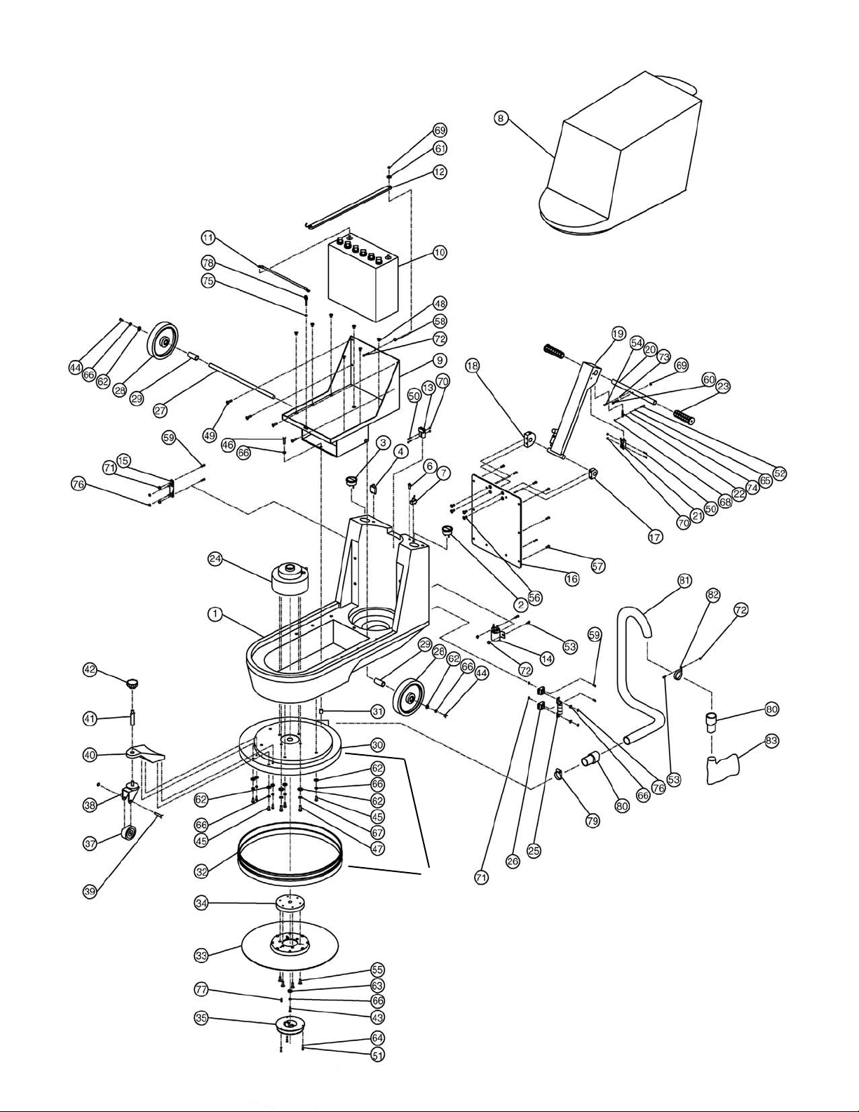
Part Number Part Name
911292 Circuit Breaker
911300 Fuse
869706 Wheel
868516 Brush Skirt
869705 Caster
860601 Paper Bag
SSS BATTERY BURNISHER, MODEL BB-1
LIMITED WARRANTY
The SSS Battery Burnisher, Model BB-1 has been manufactured, tested and inspected in accordance with specific engineering requirements,
and is WARRANTED by the manufacturer to be free from defects in workmanship and materials.
This warranty is, however, subject to the following qualifications, conditions and limitations which are set forth to provide you and all users
of the SSS Battery Burnisher with information concerning the duration, extent, availability and applicability of this Limited Warranty, the
procedure to be taken to obtain its performance and other information concerning the manufacturer’s warranty policy.
1. TO WHOM EXTENDED AND DURATION OF ITEMS COVERED
This warranty extends to the original consumer purchaser from the date it
was purchased and for the items and periods as follows:
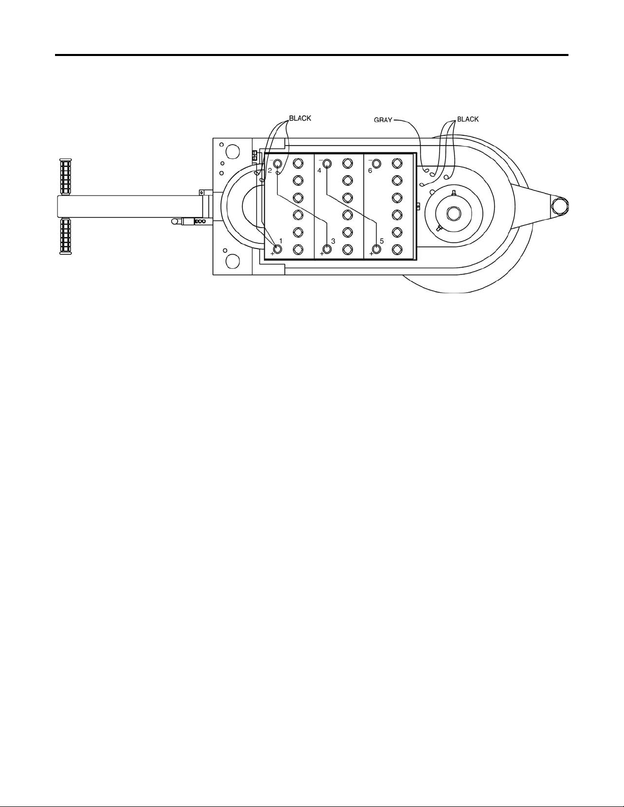
Battery Warranty: Any original Battery which becomes unserviceable
under normal use within a period of ninety (90) days from date of sale to
the original user will be repaired or replaced with one of equal specification,
F.O.B. any authorized Triple S Sales or Service Branch, with no charge to
user, except transportation costs. After the expiration of the above ninety
(90) day period, any battery which fails under normal use will be adjusted
to the original user with a new battery of equal specification on a twelve
(12) month pro rata basis from the date of purchase. Adjustment will be
determined using the then current list price, plus transportation costs. War-
ranty is rendered null and void if battery is not kept filled to the proper
level with DISTILLED WATER.
One (1) year parts and labor – All other components unless excluded
below.
2. PARTS NOT COVERED BY WARRANTY
Certain parts of the SSS Battery Burnisher require replacement in the or-
dinary course of use due to normal wear by reason of their characteristics.
This warranty does not cover the following normal wear items:
3. EXCEPTIONS AND EXCLUSIONS FROM WARRANTY
The SSS Battery Burnisher is required to be used on electric current as
indicated on the nameplate. Otherwise damage, defects, malfunctions or
other failures of the SSS Battery Burnisher arising from use on electric
current not as indicated are excepted and excluded from this warranty.
Defects, malfunctions, failure or damage of the SSS Battery Burnisher
caused by improper, unreasonable or negligent use or abuse while in the
possession of the consumer are likewise excluded from this warranty.
If repair is done on your SSS Battery Burnisher by anyone other than
those below designated as authorized to perform such work without first
having obtained factory instructions, the manufacturer, at its sole option,
may determine that this warranty will not apply and that reimbursement
for such repair will not be made because of the failure to comply with such
factory specified instructions.
4. PROCEDURE TO BE TAKEN TO OBTAIN PERFORMANCE
OF WARRANTY
To secure repair of the SSS Battery Burnisher or any warranted parts under
this warranty, the following procedure should be taken: The inoperative SSS
Battery Burnisher or warranted parts, together with satisfactory evidence
of the purchase date, must be delivered with shipping and delivery charges
prepaid to the Dealer from whom purchased.
If you are unable to locate the Dealer, you may write or otherwise com-
municate with Triple S, 2 Executive Park Drive, Billerica, MA 01862
for instructions before repair service is performed by anyone else. In such
event Triple S will provide either the location of a closely available Triple
S distributor Service Department or other factory instructions.
Upon compliance with the above procedure, all warranted defects will
be repaired, at no additional charge or costs to the consumer, and the
repaired product returned to the consumer, with all shipping and delivery
charges prepaid.
In following the procedures above set forth PLEASE MAKE CERTAIN
to state the Triple S model, type and serial number as shown on the name
plate of the SSS Battery Burnisher.
REPLACEMENT
In the event of the defect, malfunction or failure of your SSS Battery Bur-
nisher or any warranted part to conform with this warranty, the manufacturer
may at its sole option and own expense, replace the SSS Battery Burnisher
or any warranted part with another new identical or reasonably equivalent
model or part in lieu of repairing the defect.
5. NO REFUND OF PURCHASE PRICE
Triple S will not, as a matter of its warranty policy, refund the consumer’s
purchase price.
6. WARRANTY REGISTRATION CARD FOR YOUR SSS
BATTERY BURNISHER AND REQUESTS FOR INFORMATION
Please fill out the warranty registration card accompanying your SSS
Battery Burnisher, giving complete information as requested on the card,
and return to Triple S.
This warranty is in lieu of all other expressed or implied warranties.
7/04 865614
Table of contents
Other SSS Siedle Floor Machine manuals
Popular Floor Machine manuals by other brands

Tennant
Tennant 8410 Operator's manual

Steamaster
Steamaster POLIVAC PREDATOR MKII OPERATIONS MANUAL & TROUBLE SHOOTING GUIDE

Hydro-Force
Hydro-Force Olympus M3-500 operating manual

Kärcher
Kärcher BRC 30/15 C *JP operating instructions

ROOTS
ROOTS RootsSweep B70 owner's manual

Nobles
Nobles SPEED SCRUB Operator's manual

Windsor
Windsor VOYDU 10086130 operating instructions

Sapphire Audio
Sapphire Audio HOSS 700 owner's manual

APE
APE DSM 530S Translation of the original operating manual

pela tools
pela tools Sopmaskin DQS19 manual

Tennant
Tennant 97 Operator's manual

Tornado
Tornado 2-500H Professional Operation & maintenance manual