SSS Siedle SQUARE CAT GTX 20 User manual

OWNERS MANUAL
IMPORTANT: READ OWNERS MANUAL CAREFULLY
MODEL # SQUARE CAT GTX 20 OSCILLATING FLOOR MACHINE
FOR YOUR CONVENIENCE, RECORD THE FOLLOWING
IMPORTANT INFORMATION
MODEL:
SERIAL NUMBER:
DATE PURCHASED:
PURCHASED FROM:
Rev 31618

SERVICE INFORMATION
To obtain consistent performance over the life of your equipment, read though these
instructions and save them for future reference. If you require service, contact the
dealer from which the machine was purchased or an authorized service station.
Always refer to your limited Warranty for complete service information.
The model, type, and serial number are indicated on the data plate on the side of the
handle. From prompt and complete service, refer to these numbers when
inquiring about service.
Write the model and serial number of your
unit in the space provided. Refer to the
data plate on unit.
SERIAL # MODEL #
Retain this owners manual for future reference.
SERIAL NO. MODEL
VOLTS
MOTOR
PHASE
AMPS
HZ
H.P.
Service Information .................................................................................................2
Machine Specications ............................................................................................3
Features....................................................................................................................3
Important Safety Instructions...................................................................................4
Grounding Instructions ........................................................................................ 5-6
Operations ...............................................................................................................7
Guidelines For Operations .......................................................................................7
Controls...............................................................................................................7
Adjustments.........................................................................................................8
Cord Storage .......................................................................................................8
Clean Up And Storage .............................................................................................8
Floor Machine Assemblies................................................................................. 9-14
Floor Machine Parts List.................................................................................. 15-16
Limited Warranty ....................................................................................Back Cover
2

IMPORTANT SAFETY INSTRUCTIONS
When using an electrical appliance, basic precautions should always be followed, including the following:
WARNING:
ELECTRIC SHOCK CAN CAUSE SERIOUS
INJURY OR BE FATAL. PLEASE READ THE
FOLLOWING INSTRUCTIONS ON THE USE
AND OPERATIONS OF FLOOR FINISHING
MACHINES.
• Your equipped with a safety switch lock and power switch triggers designed for your
safety. Do not attempt to bypass or defeat the safety switch lock. Never use any device
to lock the power switch triggers in the “ON” position.
• Do not leave the unit plugged in. Turn o the switch and unplug the electrical cord
when not in use and before servicing or changing the brushes or pads.
• Do not allow the machine to be used as a toy. Close attention is necessary when used
near children. Do not leave the machine connected to an electrical outlet unattended.
• Use only as described in this manual. Use only manufacturer’s recommended
attachments.
• Do not use with a damaged cord or plug. If the machine is not working as it should, has
been dropped, damaged, or left outdoors, return it to a service center before using.
• Use care to keep the electrical supply cord around sharp edges or corners. Keep the cord
away from the heated surfaces.
• Connect to properly grounded (3-wire) outlet only. Refer to Grounding Instructions,
Page 5-6.
• Do not use extension cords or outlets with inadequate current carrying capacity.
• Turn o all controls before unplugging.
• Do not unplug by pulling on the cord. To unplug, grasp the plug and pull.
• Do not handle the plug or the unit with wet hands.
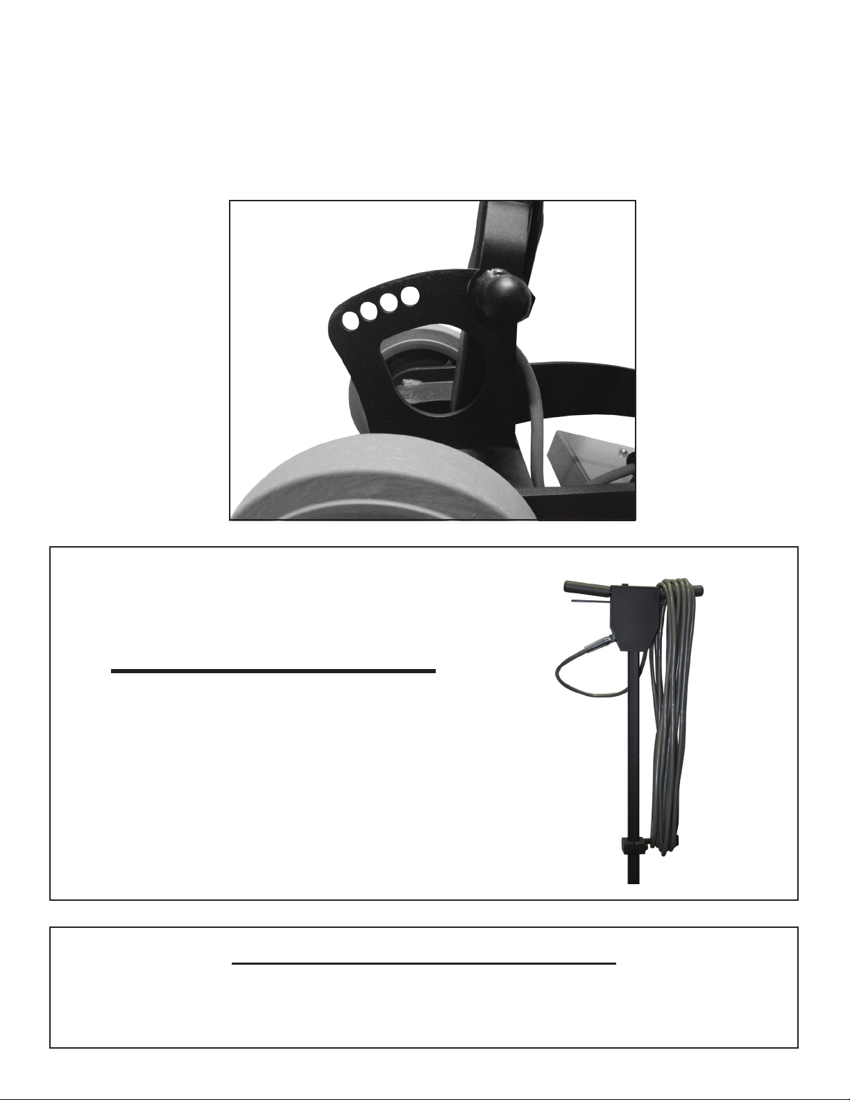
• Wind the cord no tighter than is necessary to retain it during storage. Refer to Cord
Storage, Page 8.
• Use extra care when working on or near stairs.
• Do not use in conjunction with ammable or combustible liquids such as gasoline, or
use in areas where explosive vapor or dust may be present.
• Store your unit indoors in a cool, dry area.
• Keep your work area well lighted.
• WARNING: To avoid electrical shock, use indoor only.
3

GROUNDING INSTRUCTIONS
This appliance must be grounded. If it should malfunction or break down, grounding provides a
path of least resistance for electric current to reduce the risk of electric shock. This appliance is
equipped with a cord that has an equipment-grounding conductor and grounding plug. The plug
must be plugged into an appropriate outlet that is properly installed and grounded in accordance
with all local codes and ordinances.
FOR FLOOR FINISHING MACHINES RATED LESS THAN
150 VOLTS
Improper connection of an equipment grounding conductor can result in risk of electric shock.
Check with a qualied electrician or service person if you are in doubt as to whether the outlet is
properly grounded. Do not modify the plug provided with the appliance. If it will not t the outlet,
have a proper outlet installed by a qualied electrician. This appliance is for use on a nominal 120
volt circuit and has a grounding plug that looks like the plug illustrated in Figure 1.
A temporary adapter which looks like the adapter illustrated in Figure 2 may be used to connect this
plug to a two pole receptacle, as shown, if a properly grounded outlet is not available. The temporary
adapter should be used only until a properly grounded outlet (Figure 1) can be installed by a qualied
electrician. The green colored rigid ear, lug, or the like extending from the adapter must be connected
to a permanent ground such as a properly grounded outlet box cover. Whenever the adapter is used, it
must be held in place by one metal screw.
FOR FLOOR FINISHING MACHINES RATED 150-220 VOLTS:
If the machine is provided with an attachment plug cap as shown in Figure 3, it is intended for use on
a 240 volt (nominal) circuit. No adapter is available for this cap.
WARNING:
RISK OF EXPLOSION. FLOOR SANDING
MACHINE CAN RESULT IN AN EXPLOSIVE
MIXTURE OF FINE DUST AND AIR. USE FLOOR
SANDING MACHINE ONLY IN A
WELL-VENTILATED AREA, FREE FROM ANY
FLAME OR MATCH
4

WARNING:
DO NOT USE GROUNDING
ADAPTERS ON THE UNIT IN
CANADA. CHECK WITH CANADIAN CODE
FOR PROPER EQUIPMENT USAGE.
IMPROPER USE OF GROUND ADAPTERS CAN
CAUSE SERIOUS INJURY, FIRE, OR BE FATAL.
Grounding Instructions (Continued)
5

CONTROLS
TO TURN THE MACHINE ON
The operating handle must be lowered and locked to the proper operating position before switching the
machine ON. Place both hands rmly on the handle grips with your ngers around the power triggers.
Do NOT apply pressure on the triggers before the safety switch lock is disengaged.
Disengage the safety switch lock by pushing it forward with one thumb. Then, while holding the safety
switch lock in the disengaged position, squeeze the power triggers toward the handle grips and return
your thumb to the handle grip.
To stop the machine, simply release the triggers. The safety switch lock will automatically return to the
engaged position.
GUIDELINES FOR OPERATION
• Your Square Cat GTX is a very sensitive, powerful unit. When in operation, it should be guided
gradually and smoothly without sudden or rough motions. You will want to practice with your
machine on a smooth surface until you have experience in operating it.
• For ease of operation, the pad surface will always remain level, balanced, and at on the oor at all
times.
• Always adjust the operating handle to a comfortable height. (See Handle Adjustment Page 4)
• Your unit will operate dierently on various surfaces. For example, there will be much more resist-
ance when the machine is used on a rough surface, than when it is used on a smooth surface. The
operator should be prepared to adjust for these dierences.
• BEGIN OPERATING THE SQUARE CAT GTX MAKING SURE THAT THE BACKER PAD IS
ALWAYS INSTALLED
• To move the machine to the right, guide the unit to the right.
• To move the machine to the left, guide the unit to the left.
• To move the machine forward or backward, push or pull the machine in the desired direction.
Push forward to disen-
gage safety switch lock.
6

CLEAN UP AND STORAGE
After being used, your unit can be wiped clean with a soft damp cloth and should be
stored in a clean, dry place.
ADJUSTMENTS
HANDLE ADJUSTMENT
The handle can be adjusted to any desired work position by simply pulling on the pull
pin and move the handle to the desired position. Firmly push the pull pin back into the
adjustment holes. This will lock the handle in position.
Figure 5
Pull Knob
CORD STORAGE
When not in use, loosely coil the power cord and hang on
the handle.
7

8
PRODUCED BY AN AUTODESK EDUCATIONAL PRODUCT

9

10

11

12

13

14
HANDLE ASSEMBLY
KIT3009-1BLK CORD HOOK KIT (SQUARE) 1
24 INC IN KIT3009-1BLK NUT 3/8-16 NYLOCK 2
25 INC IN KIT3009-1BLK CAP CORD HOOK SQUARE BLK 1
26 INC IN KIT3009-1BLK CORD HOOK SQUARE BLK 1
27 INC IN KIT3009-1BLK BOLT HEX 3/8-16 X 2 2
28 INC IN KIT3009-1BLK WASHER FLAT BLK 2
KIT2026-1 HANDLE MOUNTING HARDWARE KIT 1
29 INC IN KIT2026-1 BOLT HEX .500-13 X 3 1
30 INC IN KIT2026-1 NUT HEX .500-13 NYLOC 1
31 INC IN KIT2026-1 FLAT WASHER 2
32 INC IN KIT2026-1 WASHER SPRING WAVE 2
KIT1034 IN HANDLE CORD KIT 1
33 INC IN KIT1034 IN HANDLE CORD 1
34 INC IN KIT1034 GROMMET IN HANDLE 1
35 INC IN KIT1034 LOOP CLAMP 1
36 INC IN KIT1034 SCREW 10-24 X .50 THIRD ROLL PHILL PAN ZINC 1
40 INC IN KIT1034 WASHER # 10 EXTERNAL TOOTH LOCK - ZINC 4
57 INC IN KIT1034 WIRE NUT 1
39 INC IN KIT1034 SCREW 10-24 X .50 THIRD ROLL PHILL PAN ZINC 3
INC IN KIT1034 BUTTON PLUG (NOT SHOWN) 1
KIT3008-2BLK SWITCH BOX ASSEMBLY KIT 1
37 INC IN KIT3008-2BLK WARNING SWITCH BOX SAFETY LABEL REAR 1
38 INC IN KIT3008-2BLK SWITCH BOX COVER 1
39 INC IN KIT3008-2BLK SCREW 10-24 X .50 THIRD ROLL PHILL PAN ZINC 2
40 INC IN KIT3008-2BLK WASHER # 10 EXTERNAL TOOTH LOCK - ZINC 2
41 INC IN KIT3008-2BLK SWITCH BOX COVER LABEL FRONT 1
KIT2011BLK HANDLE GRIP KIT - BLK 1
42 INC IN KIT2011BLK HANDLE GRIP -BLK 2
KIT2006 SAFETY SWITCH KIT 1
43 INC IN KIT2006 SPRING 2LNG X .025 OD X .026 1
44 INC IN KIT2006 SAFETY SWITCH 1
KIT3011BLK TRIGGER REPLACEMENT KIT 1
45 INC IN KIT3011BLK TRIGGER - BLK 1
46 INC IN KIT3011BLK SPRING - TRIGGER 2
47 INC IN KIT3011BLK ROLL PIN 2
KIT1005 REPLACEMENT SWITCH KIT - MAIN 1
48 INC IN KIT1005 SWITCH 1
49 INC IN KIT1005 WASHER FLAT- ZINC 5
50 INC IN KIT1005 WASHER FLAT 5/16 USS - ZINC 1
51 INC IN KIT1005 WASHER 3/8 INTRNL TOOTH LOC-ZINC 1
52 INC IN KIT1005 SWITCH INSULATION 1
KIT3032 HANDLE ASSY LESS POWER CORD & SWITCH BOX COVER 1
63 INC IN KIT3032 HANDLE WDMT - BLK 1
INC IN KIT3032 KIT2005 STRAIN RELIEF REPLACEMENT KIT 1
INC IN KIT3032 KIT2033 HANDLE HARDWARE KIT 1
INC IN KIT3032 KIT3011BLK TRIGGER REPLACEMENT KIT 1
INC IN KIT3032 KIT2006 SAFETY SWITCH KIT 1
INC IN KIT3032 KIT3009-1BLK CORD HOOK KIT (SQUARE) 1
INC IN KIT3032 KIT1005 REPLACEMENT SWITCH KIT - MAIN 1
INC IN KIT3032 KIT2026-1 HANDLE MOUNTING HWDR KIT 1
INC IN KIT3032 KIT1043 IN-HANDLE CORD KIT 1
KIT2005 STRAIN RELIEF REPLACEMENT KIT
53 INC IN KIT2005 STRAIN RELIEF 1
54 INC IN KIT2005 WASHER STRAIN RELIEF - ZINC 2
55 INC IN KIT2005 NUT CONDUIT 1/2 1
56 E0003-2 POWER CORD 14-3 SJT BLK THIN 50 FT CORD 1
KIT2033 HANDLE HARDWARE KIT 1
57 INC IN KIT2033 WIRE NUT 1
39 INC IN KIT2033 SCREW 10-24 X .50 THIRD ROLL PHILL PAN ZINC 4
40 INC IN KIT2033 WASHER # 10 EXTERNAL TOOTH LOCK - ZINC 5
35 INC IN KIT2033 LOOP CLAMP 1
34 INC IN KIT2033 GROMMET IN HANDLE 1

15
SSS MAIN ASSY
MAIN ASSEMBLY
DETAIL PART QTY
NUMBER NUMBER DESCRIPTION REQ'D
KIT1042SSS MOTOR KIT 1.0 HP TEFC 1
1INC IN KIT1042SSS MOTOR 1
2INC IN KIT1042SSS BOLT 4
3INC IN KIT1042SSS LOCWASHER 4
KIT3037SSS SECONDARY ISOLATOR KIT 1
4INC IN KIT3037SSS BOLT 6
5INC IN KIT3037SSS LOCKWASHER 6
6INC IN KIT3037SSS ISSOLATOR 6
7INC IN KIT3037SSS NUT 6
KIT2036SSS SECONDARY ISOLATOR BRACKET KIT 1
8INC IN KIT2036 PIVOT BUSHING KIT (KIT2023) 1
9INC IN KIT2036 SECONDARY ISOLATOR BRACKET 1
KIT2023SSS PIVOT BUSHING KIT 1
8INC IN KIT2023 BUSHINGS PIVOT NYLON 2
KIT2040SSS BUTTON PLUG KIT 1
10 INC IN KIT2040SSS BUTTON PLUG 1/2 INCH 4
11 INC IN KIT2040SSS BUTTON PLUG 4
KIT3034HSV FRAME KIT - HSV 1
10 INC IN KIT3034HSV BUTTON PLUG KIT 1/2 INCH 1
11 INC IN KIT3034HSV BUTTON PLUG KIT 1
12 INC IN KIT3034HSV MAIN FRAME - HSV 1
KIT2039SSS PRIMARY ISOLATOR KIT 1
7INC IN KIT2039SSS NUT 6
6INC IN KIT2039SSS ISSOLATOR 6
13 INC IN KIT2039SSS SCREW 6
14 INC IN KIT2039SSS ECCENTRIC SCREW 6
KIT2041SSS ECCENTRIC KIT 1
15 INC IN KIT2041SSS ECCENTRIC 1
16 INC IN KIT2041SSS SET SCREW 1
14 INC IN KIT2041SSS ECCENTRIC PAD DRIVER SCREWS 6
13 INC IN KIT2041SSS PAD DRIVER SCREWS 6
17 INC IN KIT2041SSS MOTOR KEY 1
KIT2038SSS PAD DRIVER KIT 1
100 INC IN KIT2038SSS PAD DRIVER 1
101 INC IN KIT2038SSS PAD DRIVER FACE 1
102 INC IN KIT2038SSS NYLON SPACER 6
13 INC IN KIT2038SSS SCREWS PAD DRIVER 6
14 INC IN KIT2038SSS ECCENTRIC PAD DRIVER SCREWS 6
103 KIT2047SSS BACKER PAD - RED 1
INC IN KIT2047 RED PAD 2014X1 1
INC IN KIT2047 VELCRO 2
KIT2028SSS SPRING KNOB ASSEMBLY 3
104 INC IN KIT2028SSS KNOB ASSEMBLY 1
KIT2032SSS WHEEL KIT 2
18 INC IN KIT2032SSS BOLT HEX .500-13 X 3 1
19 INC IN KIT2032SSS NUT HEX .500-13 NYLOC 1
20 INC IN KIT2032SSS FLAT WASHER 5
21 INC IN KIT2032SSS WASHER SPRING WAVE 2
22 INC IN KIT2032SSS WHEEL 1
KIT3031SSS CARRIAGE FRAME 1
23 INC IN KIT3031 CARRIAGE FRAME (ONLY) 1
Page 1
MOTOR KIT 1.5 HP TEFC

LIMITED WARRANTY
Your equipment which has been manufactured, tested and inspected in accordance with carefully specied
engineering requirements, is warranted to be free from defects in material and workmanship. This Limited
Warranty is, however, subject to the Following qualications, conditions and limitations which are set forth to
provide you and all users of the equipment with information concerning the duration, extent, availability, and
applicability of this Limited Warranty, the procedure to be taken to obtain its performance, and other
information concerning the Limited Warranty policy.
The Limited Warranty is extended to the original end user as follows:
Machines: 1 year parts replacement and 1 year service labor warranty.
Replacement parts guaranteed for 90 days from date of installation against defects in material and
workmanship.
This Limited Warranty will not cover damage attributable to the following:
(1) Improper, unreasonable or negligent use or abuse of the equipment
(2) Abrasions or punctures of the equipment.
The start date of the Limited Warranty coverage shall be the purchase date of the original end user or six months
from the date the machine was shipped from the Factory, whichever comes rst.
PARTS OF EQUIPMENT NOT COVERED BY THE LIMITED WARRANTY
Certain parts of equipment require replacement in the ordinary use due to normal wear by reason of their
characteristics. Normal wear items such as cords, switches, bumpers, bearings, etc. are excluded from the
Limited Warranty.
EXCEPTIONS AND EXCLUSIONS FROM THE LIMITED WARRANTY
This equipment is required to be used on electric current as indicated on the data plate. Otherwise damage,
defects, malfunctions or other failure of the equipment arising from use on electric current not as indicated are
excepted and excluded from this Limited Warranty. Defects, malfunctions, failure or damage of the equipment
caused by improper, unreasonable or neglect use or abuse while in possession of the purchaser are likewise
excluded from this warranty. If repair is done on your equipment by anyone other than those designated as
authorized to perform such work without rst having obtained factory instructions, at its sole option, my
determine that this warranty will not apply and that reimbursement for such repair will not be made because of
the failure to comply with such factory specied instructions.
PROCEDURE TO BE TAKEN TO OBTAIN PERFORMANCE OF LIMITED WARRANTY REPAIR
To secure repair of the equipment or any warranted parts under this Limited Warranty, the following procedure
should be taken. The inoperative equipment or warranted parts, together with satisfactory evidence of the
purchase date, must be delivered, with shipping and delivery charges prepaid, to one of the following:
(1) The dealer from whom purchased;
(2) Any distributor’s service department in the United States;
(3) Any authorized service station in the United States.
If you are unable to locate any of the foregoing, you may write or otherwise communicate with your
distributor before repair service is performed by anyone else. In such event, your distributor will provide either
the location or a closely available distributor service department, or an authorized service station or other
factory instructions. Upon compliance with the above procedure, all warranted defects will be repaired, at no
additional charge or costs to the customer, and the repaired product returned to the customer, with all shipping
and delivery charges pre-paid. In following the procedures set forth, PLEASE MAKE CERTAIN to state the
model, type and serial number as shown on the data plate of the equipment.
REPLACEMENT
In the event of a defect, malfunction or failure of your equipment or any warranted part to conform with this
warranty, your distributor may, at its sole option and own expense, replace the equipment or any warranted part
with another new, identical or reasonably equivalent model or part in lieu or repairing the defect.
NO REFUND OF PURCHASE PRICE
Your distributor will not, as a matter of it’s Limited Warranty policy, refund the customer’s purchase price.
LIMITED WARRANTY REGISTRATION CARD FOR YOUR EQUIPMENT AND REQUEST FOR INFORMATION
Your distributor from whom you purchased your equipment is responsible for the registration of your Limited
Warranty with the factory. Any information or questions you may have concerning your equipment or this
Limited Warranty may likewise be secured from the factory. This Limited Warranty will give you specic legal
rights, and you may also have other rights which vary from state to state.
Table of contents
Other SSS Siedle Floor Machine manuals
Popular Floor Machine manuals by other brands

WOLFF
WOLFF ROBO-STRIPPER Translation of the original instruction

BETCO
BETCO CREWMAN AS20B Operator's manual

Superabrasive
Superabrasive LAVINA 25-S-E user manual

Alto
Alto Vision 17 Operator's manual

Hydro-Force
Hydro-Force SX-15 manual

Pullman Holt
Pullman Holt Gloss Boss GB-2000DC Operation & care instructions