SST Automation GS11-MT User manual

Embedded Modbus TCP Module
GS11-MT
User Manual
REV 1.1
SST Automation
E-mail: SUPPORT@SSTCOMM.COM
WWW.SSTCOMM.COM

www.sstcomm.com
2
Catalog
1 About the Embedded Module.................................................................................................................................... 4
1.1 General............................................................................................................................................................4
1.2 Features........................................................................................................................................................... 4
1.3 Specifications..................................................................................................................................................4
2 Hardware....................................................................................................................................................................6
2.1 Appearance......................................................................................................................................................6
2.2 Indicators.........................................................................................................................................................6
2.3 Interface.......................................................................................................................................................... 7
2.3.1 Ethernet Interface.................................................................................................................................7
2.3.2 Host Interface.......................................................................................................................................7
2.4 UART Baud Rate............................................................................................................................................ 8
2.5 Reset Signal.................................................................................................................................................... 9
3 Modbus TCP to Modbus RTU.................................................................................................................................10
3.1 Description....................................................................................................................................................10
3.2 The Flowchart of User Program................................................................................................................... 11
3.3 Real-time monitoring IP function.................................................................................................................12
3.4 Transmit the Setting IP Address Message.................................................................................................... 12
4 Modbus TCP to SST Automation-defined Protocol................................................................................................ 15
4.1 Description....................................................................................................................................................15
4.2 The Flowchart of User Program................................................................................................................... 17
4.3 Real-time monitoring IP function.................................................................................................................18
4.4 Transmit the Setting IP Address Message.................................................................................................... 18
4.5 SST Automation-defined Protocol................................................................................................................20
5 IP Address Report.................................................................................................................................................... 23
6 Dimension................................................................................................................................................................ 25
7 Development Board................................................................................................................................................. 27
7.1 Appearance....................................................................................................................................................27
7.2 Function........................................................................................................................................................ 27
7.2.1 RS232 Interface................................................................................................................................. 27
7.2.2 Baudrate Setting Switch.................................................................................................................... 28
7.2.3 Reset Key...........................................................................................................................................29
7.2.4 LED....................................................................................................................................................29
8 Configuration Software............................................................................................................................................30
8.1 Overview.......................................................................................................................................................30
8.2 Search Equipment......................................................................................................................................... 31
8.2.1 Search All Equipment of Ethernet.....................................................................................................31
8.2.2 IP Search............................................................................................................................................ 32
8.3 Advanced Configuration...............................................................................................................................33
8.3.1 Ethernet Parameters...........................................................................................................................35
8.3.2 Password............................................................................................................................................ 36
8.3.3 IP Address Report.............................................................................................................................. 37

www.sstcomm.com
3
8.3.4 Advanced Parameter.......................................................................................................................... 38
8.4 Configuration................................................................................................................................................ 39
8.4.1 Ethernet Parameters...........................................................................................................................40
8.4.2 Password............................................................................................................................................ 41
8.4.3 IP Address Report.............................................................................................................................. 42
8.5 OK, Cancel and Help....................................................................................................................................43
8.5.1 OK......................................................................................................................................................43
8.5.2 Cancel................................................................................................................................................ 44
8.5.3 Help....................................................................................................................................................44
8.6 IP Address Report......................................................................................................................................... 45
8.6.1 Parameter configuration.................................................................................................................... 45
8.6.2 IP Address Report.............................................................................................................................. 46
8.7 New............................................................................................................................................................... 46
8.8 Open..............................................................................................................................................................48
8.9 Save...............................................................................................................................................................48
9 Test Software (EemTest)......................................................................................................................................... 50
9.1 Overview.......................................................................................................................................................50
9.2 User Interface................................................................................................................................................50
9.3 Establish/Disconnect Connection................................................................................................................. 51
9.4 Set Work Mode............................................................................................................................................. 54
9.5 Receive/Transmit Data................................................................................................................................. 56

www.sstcomm.com
4
1 About the Embedded Module
1.1 General
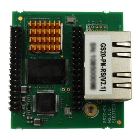
GS11-MT is an embedded Modbus TCP module and provides instant Modbus TCP connectivity via the host
interface which is SST Automation defined. Any device that supports the host interface can communicate with
GS11-MT through UART.
1.2 Features
Upgrade your UART or serial device to Modbus TCP device expediently.
Provide two kinds of operating modes.
Modbus TCP to Modbus RTU: transparent mode.
Modbus TCP to SST Automation-defined protocol: data mapping mode.
Ethernet is 10/100M adaptive.
Supports 4 Modbus TCP connects at most.
Can cache 20 Modbus TCP request messages at most in Modbus TCP to Modbus TRU mode.
Configuration software SST-EMT-CFG.
Setting the IP address via the UART( Optional Features), refer to chapter 7.
1.3 Specifications
Modbus TCP to Modbus RTU mode:
Can cache 20 request messages at most;
When the request messages buffer overflows, it can discard the current request.
Modbus TCP to SST Automation-defined protocol mode:
Support function codes: 04H、03H、06H、10H.
The size of input and output buffers can be set by users:
The size of input buffer is 256 bytes at most;

www.sstcomm.com
5
The size of output buffer is 256 bytes at most.
The host interface is UART, half duplex, 8 data bits, one stop bit, and no parity, and support 9600, 19200,
38400, 57600, 115200, 230400 baud rate.
Power: +3.3VDC (3.14 ~ 3.45V), 182mA.
Environmental temperature: -40 ~ 85℃, humidity: 5% ~ 90%.
Dimension (W*H*D): 0.88 in*0.95 in*1.46 in (22.6mm*24.2mm*37.2mm).

www.sstcomm.com
6
2 Hardware
2.1 Appearance
2.2 Indicators
Indicator
Status
Description
Green
Off
No network connection
Always on
Have network connection
Yellow
Off
No network data transmitting or receiving
Blinking
Have network data transmitting or receiving
Network connecting
indicator
Network activity
indicator

www.sstcomm.com
7
2.3 Interface
2.3.1 Ethernet Interface
The Ethernet interface uses an 8-line RJ-45 interface, and the pin definitions are as follows:
Pins
Signals
Descriptions
Pin 1
TXD+
Transmit Data+
Pin 2
TXD-
Transmit Data-
Pin 3
RXD+
Receive Data+
Pin 4
BID+
Bi-directional Data+
Pin 5
BID-
Bi-directional Data-
Pin 6
RXD-
Receive Data-
Pin 7
BID+
Bi-directional Data+
Pin 8
BID-
Bi-directional Data-
2.3.2 Host Interface
GS11-MT has a 20-pin socket connector (needle-type), including power, UART and GPIO. The pin position
and definition are as follows:

www.sstcomm.com
8
Pins
Signals
Description
1 ~
6
NC
Reserved
7
RXD
UART Receive (Input), connect with TXD of host processor or MCU
8
TXD
UART Transmit (Output), connect with RXD of host processor or MCU
9
NC
Reserved
10
/RUN
The status of GS11-MT (Output), and need a 10K pull-up resistor on user board.
Logic 1: The GS11-MT module is in starting.
Logic 0: The module’s start has been completed.
If this pin is pull down to low voltage before starting the module(by using a 1K
pull-down resistor), the module will start with default IP address (192.168.0.11), and
this mode is used to update the firmware of GS11-MT.
11
BAUD2
Set the UART baud rate (Input), see the following table.
12
BAUD1
13
BAUD0
14
/RESET
Reset signal (Input), Active low.
15
+3.3V
+3.3V DC power Supply
16
GND
GND power Supply
17 ~
19
NC
Reserved
20
/DATAEXCH
Data Exchange (Output), and need a 10K pull-up resistor on the user board.
Logic 1: The module is in non-data exchange state (such as start state, waiting for
initialization state that waits users to send messages to initialize, start the TCP
protocol stack, etc.)
Logic 0: The module is ready for data exchange.
2.4 UART Baud Rate
UART baud rate settings are as follows:

www.sstcomm.com
9
Index
BAUD2
BAUD1
BAUD0
Baud Rate (bps)
0
0
0
0
Reserved, don’t use
1
0
0
1
Reserved, don’t use
2
0
1
0
9600
3
0
1
1
19200
4
1
0
0
38400
5
1
0
1
57600
6
1
1
0
115200
7
1
1
1
230400
2.5 Reset Signal
GS11-MT RESET (Pin 14) is hardware reset signal input. When the RESET pin is pulled down to GND or
low to 2.88V lasting for 1 millisecond, the module will be forced to reset, and the host must wait for 250
milliseconds (typical value, after reset the module), and then the host must check the PIN10 (/RUN) and PIN20
(/ DATAEXCH). If the two pins are Logic 0, then the host can exchange data.

www.sstcomm.com
10
3 Modbus TCP to Modbus RTU
3.1 Description
GS11-MT acts as a Modbus TCP server at the Ethernet side, and a Modbus RTU master at the serial port side.
GS11-MT receives Modbus TCP request messages come from Ethernet, then convert the message format from
TCP to RTU, and send them to the serial port. RTU response messages receiving from the serial port are converted
to Modbus TCP response messages and are transmitted to corresponding Modbus TCP master.
The procedure of message transmission is as follows:
GS11-MT
Modbus RTU
Modbus TCP
Request1
Request 2
Request…
Request 1
Request 2
Request…
Response1
Response 2
Response…
Response 1
Response 2
Response…
Every Modbus TCP can connect multiple requests at the same time in this mode, and all connections share
the request buffer which can cache 20 frames.

www.sstcomm.com
11
3.2 The Flowchart of User Program

www.sstcomm.com
12
3.3 Real-time monitoring IP function
If the GS11-MT is set to DHCP, then the module will monitor its IP when it is running. If IP changed, it will
pull up /DataExch pin to logic 1.Then two cases: 1.Using configuration software setting IP address mode: The
module will obtain an IP again. User needs to read / DataExch pin state. If it re-becomes logic 0, indicating that
the module has obtained IP, and the module can begin to communicate; 2.Using UART setting IP address mode:
GS11-MT will wait the user to send the setting IP address message, and the next step is the same with the first
initialization.
3.4 Transmit the Setting IP Address Message
When using UART to set the module IP address, user board (host) need to send initialize commands to
GS11-MT.
GS11-MT reads these pins BAUD0, BAUD1 and BAUD2 that select The UART baud rate when it power on
or reset.
1. Request message--- (user board->module)
Byte
Modbus TCP to Modbus RTU Mode
0
message length is 17 which includes all following bytes except the check sum byte and the length
byte , high-byte first
1
2
Reserved, always 0
3
IP Configuration Mode, 0: Static Configuration; 1: DHCP
4
IP Address, high-byte first
5
6
7
8
Subnet Mask, high-byte first
9
10
11

www.sstcomm.com
13
12
Default Gateway Address, high-byte first
13
14
15
16
Reserved, always 0
17
Reserved, always 0
18
Reserved, always 0
19
Check sum, byte 0+byte 1+…+byte 18
2. Response message--- (module->user board)
Byte
Correct Response
Incorrect Response
0
Data length is 2
Data length is 2
1
0: Correct
Error code (not 0)
2
0
Extra error code
3
Check sum, byte 0+byte 1+byte 2
Check sum, byte 0+byte 1+byte 2
3. Error code
Index
Error Code
Explanation
0
1
Check sum error.
1
2
Data length error.
2
3
IP configuration mode does not exist.
4. Extra error code is always 0xFF.
GS11-MT also has sending IP address reporting function (via UART).To enable the function, you must meet
the following two conditions: 1. The module is set to DHCP; 2. In the above request message table, the Byte 2 is
set to 0x01; After the user transmits the setting IP address message, the user will receive "0x2E" per second, until
the GS11-MT successfully obtain an IP address. Then the user will receive a message, and its format is shown as
follows:

www.sstcomm.com
14
IP Address Report:
Byte
IP Address Report
0
message length is 12 which includes all following bytes except the check sum byte and the length
byte , high-byte first
1
IP Address, high-byte first
2
3
4
5
Subnet Mask, high-byte first
6
7
8
9
Default Gateway Address, high-byte first
10
11
12
13
Check sum, byte 0+byte 1+…+byte 12
Eg:0C C0 A8 00 BB FF FF FF 00 C0 A8 00 01 95
The first byte is the length. The length does not include length of checksum. The each next four bytes are IP
address, subnet mask, and gateway address. Last byte is checksum.

www.sstcomm.com
15
4 Modbus TCP to SST Automation-defined
Protocol
4.1 Description
GS11-MT acts as a Modbus TCP server at the Ethernet side, and the serial protocol is SST
Automation-defined protocol. Modbus TCP communication and serial communication of GS11-MT are
independent, and exchange data between through the input and output data buffer inside GS11-MT. User board
can exchange data with EMT331 according to the SST Automation –defined protocol of GS11-MT.
The procedure of message transmission is as follows:
GS11-MT
SST-defined protocol
Modbus TCP
Request1
Request2
Request…
Request a
Request b
Request …
Response1
Response2
Response…
Response a
Response b
Response…
In this mode, Modbus TCP only supports 03H、04H、06H、10H function codes.
Note: In this mode, each Modbus TCP client just transmits one request message, and do not transmits another
request message until the Modbus TCP client receives the response or the response timeout.
The corresponding relationship of data buffer and function codes is as follows:

www.sstcomm.com
16
Input
Data
Buffer
Output
Data
Buffer
04H Function Code
06H Function Code
10H Function Code
03H Function Code
04H function code is used to read input data; 06H and 10H function codes are used to write output data; 03H
function code is used to read back output data, and then multiple Modbus TCP masters can exchange data using
this function code.

www.sstcomm.com
17
4.2 The Flowchart of User Program

www.sstcomm.com
18
4.3 Real-time monitoring IP function
If the GS11-MT is set to DHCP, then the module will monitor its IP when it is running. If IP changed, it will
pull up /DataExch pin to logic 1.Then two cases: 1.Using configuration software setting IP address mode: The
module will obtain an IP again. User needs to read / DataExch pin state. If it re-becomes logic 0, indicating that
the module has obtained IP, and the module can begin to communicate; 2.Using UART setting IP address mode:
GS11-MT will wait the user to send the setting IP address message, and the next step is the same with the first
initialization.
4.4 Transmit the Setting IP Address Message
When using UART to set the module IP address, user board (host) is the communication initiator, and
GS11-MT responses. The module waits until it receives the setting IP address message.
GS11-MT reads these pins BAUD0, BAUD1 and BAUD2 that select The UART baud rate when it power on
or reset.
1. Request message--- (user board->module)
Byte
Modbus TCP to SST Automation-defined Protocol
0
Data length is17 which includes all following bytes except the check sum byte and the length byte,
high-byte first
1
2
Always 0, except in one case which refer to chapter 4.3
3
IP Configuration Mode, 0: Static Configuration; 1: DHCP
4
IP Address, high-byte first
5
6
7
8
Subnet Mask, high-byte first
9
10
11

www.sstcomm.com
19
12
Default Gateway Address, high-byte first
13
14
15
16
Reserved, always 0
17
Reserved, always 0
18
Reserved, always 0
19
Check sum, byte 0+byte 1+…+byte 18
2. Response message--- (module->user board)
byte
Correct Response
Incorrect Response
0
Data length is 2
Data length is 2
1
0: Correct
Error code (not 0)
2
0
Extra error code
3
Check sum, byte 0+byte 1+byte 2
Check sum, byte 0+byte 1+byte 2
3. Error code
Index
Error Code
Explanation
0
1
Check sum error.
1
2
Data length error.
2
3
IP configuration mode does not exist.
4. Extra error code is always 0xFF
GS11-MT also has sending IP address reporting function (via UART).To enable the function, you must meet
the following two conditions: 1. The module is set to DHCP; 2. In the above request message table, the Byte 2 is
set to 0x01; After the user transmits the setting IP address message, the user will receive "0x2E" per second, until
the GS11-MT successfully obtain an IP address. Then the user will receive a message, and its format is shown as
follows:
IP Address Report

www.sstcomm.com
20
Byte
IP Address Report
0
message length is 12 which includes all following bytes except the check sum byte and the length
byte , high-byte first
1
IP Address,highAddress, high-byte first
2
3
4
5
Subnet Mask, high-byte first
6
7
8
9
Default Gateway Address, high-byte first
10
11
12
13
Check sum, byte 0+byte 1+…+byte 12
Eg: 0C C0 A8 00 BB FF FF FF 00 C0 A8 00 01 95
The first byte is the length. The length does not include length of checksum. The each next four bytes are IP
address, subnet mask, and gateway address. Last byte is checksum.
4.5 SST Automation-defined Protocol
User board is the communication initiator, and GS11-MT responses.
The request messages contain input data, and the response messages contain output data. The communication
process is as follows:
Table of contents
Other SST Automation Control Unit manuals
