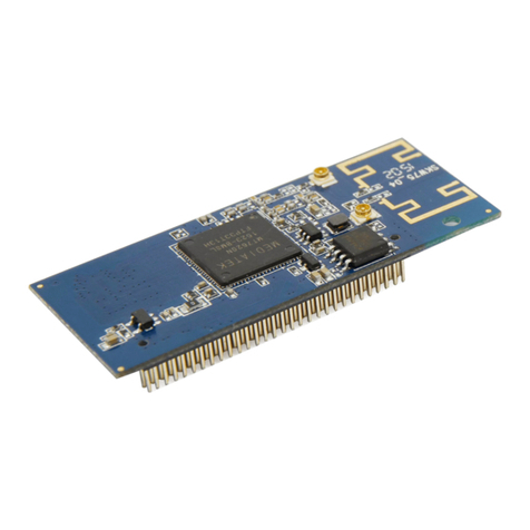
SST Automation GS20-PN-RS User manual

Embedded PROFINET IO RT Interface Module
GS20-PN-RS
User Manual
V2.1
Rev B
SST Automation
E-mail: SUPPORT@SSTCOMM.COM
WWW.SSTCOMM.COM

2
Important Information
Warning
The data and examples in this manual cannot be copied without authorization. SSTCOMM reserves the right to
upgrade the product without notifying users.
The product has many applications. The users must make sure that all operations and results are in accordance
with the safety of relevant fields, and the safety includes laws, rules, codes and standards.
Copyright
Copyright © 2021 by SST Automation. All rights reserved.
Trademark
is the registered trade mark of SST Automation.
Technical Support Contact Information
www.sstcomm.com
E-mail: support@sstcomm.com

3
Catalog
1 Product Overview...................................................................................................................................................... 4
1.1 Product Function.............................................................................................................................................4
1.2 Product Features............................................................................................................................................. 4
1.3 Technical Specifications................................................................................................................................. 4
1.4 Revision History............................................................................................................................................. 5
2 Product Development Process................................................................................................................................... 6
3 Hardware Description................................................................................................................................................ 7
3.1 Hardware Dimensions.................................................................................................................................... 7
3.2 Socket Dimensions of Network Interface Module......................................................................................... 8
3.3 Connector Pin Definitions.............................................................................................................................. 9
3.3 Ethernet Interface..........................................................................................................................................11
4 Software Description............................................................................................................................................... 12
4.1 UART Connection........................................................................................................................................ 12
4.2 General Communication Process..................................................................................................................12
4.2.1 Initialization and Entering Configuration Mode............................................................................... 13
4.2.2 Enter Run Mode.................................................................................................................................14
4.2.3 Network Communication.................................................................................................................. 14
4.2.4 Implementation of Communication...................................................................................................15
4.3 Communication between Host and the Module........................................................................................... 16
4.3.1 Host Commands.................................................................................................................................16
4.3.2 Module (Adapter) Commands...........................................................................................................20
4.3.3 Module (Adapter) Responses............................................................................................................ 21
4.3.4 Host Socket Commands.....................................................................................................................24
4.3.5 Module (Adapter) Socket Commands and Responses...................................................................... 28
5 Items and Baskets.................................................................................................................................................... 31
5.1 PROFINET Items......................................................................................................................................... 31

4
1 Product Overview
1.1 Product Function
The GS20-PN-RS provides the PROFINET slave interface for developing products PROFINET communication
through UART.
1.2 Product Features
Quick developing: Without the details of PROFINET protocol or PROFINET development system, you can
develop the PROFINET product quickly and easily, just edit the configuration files and GSDML files
according to actual applications.
Easy to use: The host processor can read / write input / output data to the GS20-PN-RS through serial
interface (UART) , and the GS20-PN-RS will automatically convert data into PROFINET data and transfer
data to PROFINET PLC.
Typical Application: It can be widely used in various products, such as frequency converter, motor start
protection device, intelligent high and low voltage electrical apparatus, electric quantity measuring device,
various transmitters, intelligent field measuring equipment and meters, etc.
1.3 Technical Specifications
[1] Supports PROFINET IO RT V2.2 Protocol.
[2] PROFINET input-byte and output-byte number are configurable, up to 384 input bytes and384 output bytes.
[3] Supports serial interface (UART).
[4] GS20-PN-RS to baseboard interface is a CMOS TTL asynchronous serial port, baud rate: Fixed to 115.2K,
data bit: 8 bit, even check, 1 stop bit.
[5] Supports even check of characters and CRC check of frames to ensure data security.
[6] Supports TCP and UDP.
[7] Power: 3.3VDC, 500mA (suggested 2W / 3.3VDC).

5
[8] Operation temperature: -4℉~122℉(-20℃~50℃), Humidity: 5%~ 95% (non-condensing).
[9] External dimension (W*H*D):1.85 in*0.67 in*2.22 in (47mm*17mm*56.3mm).
1.4 Revision History
Revision
Date
Chapter
Description
V2.1, Rev A
6/22/2015
All
First release V2.1 manual
V2.1, Rev B
10/26/2020
All
Revision

6
2 Product Development Process
Start
Step 1: Hardware Design
According to the chapter 3 Hardware Description to complete the hardware schematic diagram and PCB diagram
design.
Step 2: Software Design
According to the chapter 4 Software Description to program the configuration for the GS20-PN-RS and the
baseboard.
Step 3: Data Communication Debugging
Preliminary debugging, mainly to make sure the UART communication between the baseboard and the
GS20-PN-RS is normal. The debug information refers to the user manual chapter 4 Software Description.
Step 4: Edit the GSDML File
Edit the GS20-PN-RS.GSDML file according to the configuration of the GS20-PN-RS. Please see “GS20-PN-RS
Design Guide” for details (downloaded at www.sstcomm.com).
Step 5: Design and Set up a Debugging System
Step 6: Install, Configure and Debug the Product
END

7
3 Hardware Description
3.1 Hardware Dimensions
Figure 1 - GS20-PN-RS Dimensions (Plane View)
Notes: Length: 2.137 inch (54.3mm). Width: 2.244 inch (57mm).
Figure 2 - Ethernet Interfaces of GS20-PN-RS

8
Figure 3 - GS20-PN-RS Side View
3.2 Socket Dimensions of Network Interface Module
The following dimensions are in inch.
Figure 4 - Socket Dimensions of the Network Interface Module

9
3.3 Connector Pin Definitions
Figure 5 - Connector Pin of the Network Interface Module
Notes: The GS20-PN-RS supports UART Host Interfaces only.
Table 1 - Connector Pin Definitions of X1-A
X1 Pin
Signal Name
Description
Function
A1
UIC0_1
Input
Write Data Bit 1 for Parallel Host Interface
A2
UIC0_2
Input
Write Data Bit 2 for Parallel Host Interface
A3
UIC0_3
Input
Write Data Bit 3 for Parallel Host Interface
A4
UIC0_4
Input
Write Data Bit 4 for Parallel Host Interface
A5
UIC0_5
Input
Write Data Bit 5 for Parallel Host Interface
A6
UIC0_6
Input
Write Data Bit 6 for Parallel Host Interface
A7
UIC0_15
Input
Write Data Bit 15 for Parallel Host Interface
A8
UIC0_17
Output
“INT4” connection for Parallel Host Interface
A9
INT4
Input
Interrupt 4, has 10K pull-up resistor on module;
“USED” for Parallel Host Interface
A10
NC
Not connected
Do not connect
A11
NC
Not connected
Do not connect
A12
NC
Not connected
Spare pin
A13
NC
Not connected
Spare pin
A14
NC
Not connected
Spare pin
A15
NC
Not connected
Spare pin
A16
NC
Not connected
Spare pin

10
Table 2 - Connector Pin Definitions of X1-B
X1 Pin
Signal Name
Description
Function
B1
+3V3
Power
+3.3V Power Supply Input
B2
BOOTLOAD_EN_N
Input
Bootload Enable (active low), has 10K pull-up
resistor on module
B3
UIC0_11
Input
Write Data Bit 11 for Parallel Host Interface
B4
UIC0_12
Input
Write Data Bit 12 for Parallel Host Interface
B5
UIC0_10
Input
Write Data Bit 10 for Parallel Host Interface
B6
UIC0_9
Input
Write Data Bit 9 for Parallel Host Interface
B7
UIC0_8
Input
Write Data Bit 8 for Parallel Host Interface
B8
MAN_RESET_N
Input
Manual Reset Input to FIDO’s supervisor IC (active
low); Not 5V Tolerant
B9
+3V3
Power
+3.3V Power Supply Input, must be connected to
the same Power with X1-B1
B10
UIC0_13
Input
Write Data Bit 13 for Parallel Host Interface
B11
NC
Not connected
Do not connect
B12
NC
Not connected
Do not connect
B13
NC
Not connected
Do not connect
B14
NC
Not connected
Do not connect
B15
NC
Not connected
Do not connect
B16
RESET_OUT_N
Output
FIDO’s reset output
Table 3 - Connector Pin Definitions of X1-C
X1 Pin
Signal name
Description
Function
C1
GND
GND
Signal Ground
C2
UIC1_17
Output
“FIFONOTEMPTY_N” for Parallel Host Interface
C3
UIC1_16
Input
TX for UART Host Interface (Connect to Host RX);
Or “RD_SEL_N” for Parallel Host Interface
C4
UIC1_0
Output
RX for UART Host Interface (Connect to Host TX);
Or Read Data Bit 0 for Parallel Host Interface
C5
UIC0_0
Input
Write Data Bit 0 for Parallel Host Interface
C6
UIC0_16
Input
“WR_SEL_N” for Parallel Host Interface
C7
UIC0_14
Output
Write Data Bit 14 for Parallel Host Interface
C8
UIC0_7
Output
Write Data Bit 7 for Parallel Host Interface
C9
GND
GND
Signal Ground
C10
CHASSIS GND
Chassis GND
Ethernet line-side isolated ground
C11
NC
Not connected
Do not connect
C12
NC
Not connected
Do not connect
C13
NC
Not connected
Do not connect
C14
NC
Not connected
Do not connect
C15
NC
Not connected
Do not connect
C16
NC
Not connected
Spare pin

11
Table 4 - Connector Pin Definitions of X1-D
X1 Pin
Signal name
Description
Function
D1
UIC1_1
Output
Read Data Bit 1 for Parallel Host Interface
D2
UIC1_2
Output
Read Data Bit 2 for Parallel Host Interface
D3
UIC1_3
Output
Read Data Bit 3 for Parallel Host Interface
D4
UIC1_4
Output
Read Data Bit 4 for Parallel Host Interface
D5
UIC1_5
Output
Read Data Bit 5 for Parallel Host Interface
D6
UIC1_6
Output
Read Data Bit 6 for Parallel Host Interface
D7
UIC1_7
Output
Read Data Bit 7 for Parallel Host Interface
D8
UIC1_8
Output
Read Data Bit 8 for Parallel Host Interface
D9
UIC1_9
Output
Read Data Bit 9 for Parallel Host Interface
D10
UIC1_10
Output
Read Data Bit 10 for Parallel Host Interface
D11
UIC1_11
Output
Read Data Bit 11 for Parallel Host Interface
D12
UIC1_12
Output
Read Data Bit 12 for Parallel Host Interface
D13
UIC1_13
Output
Read Data Bit 13 for Parallel Host Interface
D14
UIC1_14
Output
Read Data Bit 14 for Parallel Host Interface
D15
UIC1_15
Output
Read Data Bit 15 for Parallel Host Interface
D16
NC
Not connected
Spare pin
3.3 Ethernet Interface
Each Ethernet interface of the GS20-PN-RS is a RJ-45 connector.
Figure 6 - RJ-45 Connector
Table 5 - Pin Definitions of RJ-45 Port
Pin
Signal Description
S1
TXD+, Transceiver Data+, Output
S2
TXD-, Transceiver Data-, Output
S3
RXD+, Receive Data+, Input
S4
Bi-directional Data+
S5
Bi-directional Data-
S6
RXD-, Receive Data-, Input
S7
Bi-directional Data+
S8
Bi-directional Data-

12
4 Software Description
4.1 UART Connection
The UART Host Interface is implemented using two pins from the Network Interface. These pins are X1-C3 and
X1-C4.
The UART will be configured to operate at a fixed baud rate of 115200 baud using an 8 bit data word with even
parity and 1 stop bit.
Figure 7 - UART Interface Connection
4.2 General Communication Process
The module is designed with four operational modes: Standby, Configuration, Pend and Run. On power up or
reset, the module enters Standby Mode. It will remain in Standby Mode until a Host Request Status frame is
received. Once this frame is received, the module will enter Configuration Mode. This process provides a way to
synchronize the host and the module after start up. In Configuration Mode, the module operates in a strict
command/response manner with the host issuing configuration commands and the module providing status
responses. After the host issues a Host Start frame, the module will enter Pend mode while it applies the

13
configuration information selected by the host and waits for configuration information from the network’s DHCP
server (only if DHCP is enabled). Once all of the configuration information has been received and applied, the
module will enter Run mode. Only when in Run Mode does the module provide unrequested data to the host.
Before successfully entering Run Mode, the host must set a device (using the Add Device frame), add at least one
item (using the Add Item frame)and set the network settings (using the Set Network Configuration frame). In Run
Mode, the data sent to the host by the module consists of four frame types: Network Data, Module (Adapter)
Events, Socket Data and Socket Events.
Notes: In lieu of sending the Add Device and Add Item frames, the host can send the Add Basket frame to satisfy
the requirement of adding a device and at least one item. However, it should be noted that these two configuration
methods are mutually exclusive. Once the host sends an Add Device frame or an Add Item frame, the Add Basket
frame becomes locked until the module is reset and will not be processed if received by the module. Conversely,
once the host sends an Add Basket frame, the Add Device and Add Item frames become locked and will not be
processed.
To use network sockets with the module, the module must first be in Run mode. Once in Run mode, the host can
open a socket. Once a socket has been opened, the host may set options for the socket if they are desired. The host
can send and receive socket data once the socket has been successfully opened and any desired options have been
set. To check the status of a particular socket, the host can poll the module for the status of the socket. Similar to
the way Bus data is sent to the host, socket data is sent from the module to the host spontaneously -- the host does
not need to poll the module for socket data. Once the host no longer needs a network socket, the host
should close the socket. The following table indicates the conditions under which each of the different frames will
be sent.
4.2.1 Initialization and Entering Configuration Mode
The initialization sequence consists of a status request from the host and a response from the module. Once the
module has received a status request from the host after power up or reset, the module will enter Configuration
Mode.
With the module in Configuration Mode, the host can now send an Add Basket frame (or optionally an Add
Device frame plus an Add Item frame) to indicate which preloaded device and item to use. This will tell the

14
module the I/O data size and other information needed to configure the bus. Once the device and item(s) has/have
been selected, the module will need its network settings to be configured. To do this, the host will send a Network
Configuration frame containing the network configuration information. Details on the required configuration
information of PROFINET protocol are contained below.
Frame Name
Add Basket
(or Add Device + Add Item)
Set Network Configuration
Required
Required
(select “NVM” as addressing mode)
4.2.2 Enter Run Mode
Once the host has sent the required configuration, (i.e. added a device, added one or more items, and set the
network configuration) the host can request that module start by sending a Host Start frame. The module will enter
Pend mode while all of the applicable configuration and network settings are applied. Once this is done, the
module will enter Run mode.
4.2.3 Network Communication
Once the module is in Run Mode, the host can send data to the module to be produced on the network and the
module can consume data from the network and relay that data to the host.
While the module is in Run Mode, the host can also open a network socket and implement its own or any other
protocol via TCP/IP or UDP/IP. To use a socket, the host must open a socket on the module by sending a Host
Open Socket frame. In the Module (Adapter) Response frame, the module will supply the host with a socket
handle that the host should use to reference the socket when setting socket options, or sending socket data, etc. In
this manner, the host can maintain and reference multiple sockets with multiple configurations. Once the module
has opened the socket and supplied the host with a socket handle, the host can immediately begin using the socket
to send and receive data. The host may also set any desired socket options at this time.
Socket data reception works in the same way as network data reception. When new socket data comes in, the data
is immediately relayed to the host. This process is spontaneous to the host. In addition to spontaneous socket data,
the module will also relay spontaneous socket events such as a remote connection or disconnection along with the

15
pertinent details for the event. With this spontaneous socket event information, the host can make decisions about
whether or not to keep the socket open, etc.
4.2.4 Implementation of Communication
Figure 8 - Example Communication Flow

16
4.3 Communication between Host and the Module
The data communication between the host and the module (GS20-PN-RS) will use the same basic format. A frame
consists of an ID byte, a data length byte, some data bytes, and 2-byte CRC, as shown below:
Byte 1: Frame ID byte
Byte 2: Data length
Byte 3 to Byte n: Transferred data
Byte n+1, n+2: Frame checksum (2 bytes, uses Modbus/RTU CRC algorithm)
4.3.1 Host Commands
Add Basket
Adds the specified basket content (single device and one or more items)
● Valid in Configuration Mode only - generate an error in all other modes
● Sent once, otherwise will generate an error
● Will lock Add Device frame and Add Item frame
● If either Add Device frame or Add Item frame has previously been sent, will generate an error.
Index
Data Type
Value
Number of Bytes
0
Frame ID
0x01
1 byte
1
Data length
2
1 byte
Frame Data
2
Basket ID
--
2 bytes
4
CRC
--
2 bytes
Add Device
Adds the specified device
● Valid in Configuration Mode only - generate an error in all other modes
● Sent once, otherwise will generate an error
● Will lock Add Basket frame
● If Add Basket frame has previously been sent, will generate an error
Index
Data Type
Value
Number of Bytes
0
Frame ID
0x02
1 byte
1
Data length
4
1 byte

17
Frame Data
2
Device ID
--
2 bytes
8
CRC
--
2 bytes
Add Item
Adds the specified item
● Valid in Configuration Mode only - generate an error in all other modes
● Will lock Add Basket frame
● If Add Basket frame has previously been sent, will generate an error
Index
Data Type
Value
Number of Bytes
0
Frame ID
0x03
1 byte
1
Data length
6
1 byte
Frame Data
2
Item ID
--
2 bytes
4
Location
--
4 bytes
8
CRC
--
2 bytes
* The Item ID is a 4-digit decimal number. The first digit indicates the Item type and the other three digits indicate
the Item size, as the following tables show:
Input Bytes
Item ID
Output Bytes
Item ID
Input&Output Bytes
Item ID
1
1001
1
2001
1
3001
2
1002
2
2002
2
3002
4
1004
4
2004
4
3004
8
1008
8
2008
8
3008
16
1016
16
2016
16
3016
32
1032
32
2032
32
3032
64
1064
64
2064
64
3064
128
1128
128
2128
128
3128
512
1512
512
2512
512
3512
For example, add an 8-byte Input&Output Item to No.1 slot. The corresponding Item ID is 3008, as 0x0BC0 in
HEX.
Host --> Module: 03 06 0B C0 00 00 00 01 A6 B4
Module --> Host: F0 06 00 03 00 04 02 01 EC 2E (State: Configuration Mode, Ether: Broken, PLC: Broken)
Set Network Configuration
Sets Network configuration information

18
● Valid in Configuration Mode only - generate an error in all other modes
● If the Addressing Mode is NVM, the supplied IP address, subnet mask, gateway address, DNS1 and
DNS2 addresses will be ignored and the corresponding values stored in Non-Volatile Memory will be
used
Index
Data Type
Value
Number of Bytes
0
Frame ID
0x10
1 byte
1
Data length
n+21
1 byte
Frame Data
2
Address Mode
--
1 byte
(Static = 0, DHCP = 1, NVM = 2)
3
IP Address
--
4 bytes (big endian)
7
Subnet mask
--
4 bytes (big endian)
11
Gateway Address
--
4 bytes (big endian)
15
DNS 1 Address
--
4 bytes (big endian)
19
DNS 2 Address
--
4 bytes (big endian)
23
Host Name
--
N bytes (Max 63bytes), string
n+23
CRC
--
2 bytes
Set MAC Address
Sets the MAC address for the module
● Valid in Configuration Mode only
● Optional - the MAC address stored in non-volatile memory will be used if this frame is not received
from the host
Index
Data Type
Value
Number of Bytes
0
Frame ID
0x11
1 byte
1
Data length
6
1 byte
Frame Data
2
MAC Address
--
6 bytes (big endian)
8
CRC
--
2 bytes
Set Serial Number
Sets the serial number for the module
● Valid in Configuration Mode only
● Optional - the serial number stored in non-volatile memory will be used if this frame is not received
from the host

19
Index
Data Type
Value
Number of Bytes
0
Frame ID
0x12
1 byte
1
Data length
4
1 byte
Frame Data
2
Serial Number
--
4 bytes (big endian)
6
CRC
--
2 bytes
Request Status
Requests the current status of the module (adapter)
● Valid in all modes
● Only elicits a response frame
Index
Data Type
Value
Number of Bytes
0
Frame ID
0x20
1 byte
1
Data length
0
1 byte
Frame Data: None
2
CRC
--
2 bytes
Request Reset
Requests a reset of the module
● Not valid in Standby Mode
● Reset request must be sent two times consecutively to reset the module
Index
Data Type
Value
Number of Bytes
0
Frame ID
0x21
1 byte
1
Data length
0
1 byte
Frame Data: None
2
CRC
--
2 bytes
Request Start
Requests the module to enter Run Mode
● Valid in Configuration Mode only
● Request the module to enter Run Mode
● Successfully entering Run Mode requires all required configuration frames o have been sent before
Index
Data Type
Value
Number of Bytes
0
Frame ID
0x22
1 byte

20
1
Data length
0
1 byte
Frame Data: None
2
CRC
--
2 bytes
Set Bus Data
Contains data to be produced on the Bus
● Valid in Run Mode only
● Request the module to process data on the bus
● The data length must match the output data size from the configuration information
● Data must be placed in the Frame Data section according to the items in use (See chapter 5 for details)
Index
Data Type
Value
Number of Bytes
0
Frame ID
0x30
1 byte
1
Data length
n
2 bytes, n = output data length (set
in configuration data)
Frame Data
3
Output Data
--
n bytes to produced on the bus
n+3
CRC
--
2 bytes
4.3.2 Module (Adapter) Commands
Module (Adapter) Data
Contains data consumed from the network
● Sent to the host by the module (adapter) every 250ms once a PLC connection has been made
● Also sent immediately when the bus data changes
● Data will be packed in the Frame Data section according to the items in use (See chapter 5 for details)
Index
Data Type
Value
Number of Bytes
0
Frame ID
0x31
1 byte
1
Data length
n
2 bytes, n = input data length (set
in configuration data)
Frame Data
3
Input Data
--
n bytes to produced on the bus
n+3
CRC
--
2 bytes
Table of contents
Other SST Automation Control Unit manuals
