manuals.online logo
Brands
  1. Home
  2. •
  3. Brands
  4. •
  5. BENDIX
  6. •
  7. Control Unit
  8. •
  9. BENDIX PRESSURE PROTECTION VALVES User manual

BENDIX PRESSURE PROTECTION VALVES User manual

1
SD-03-2010
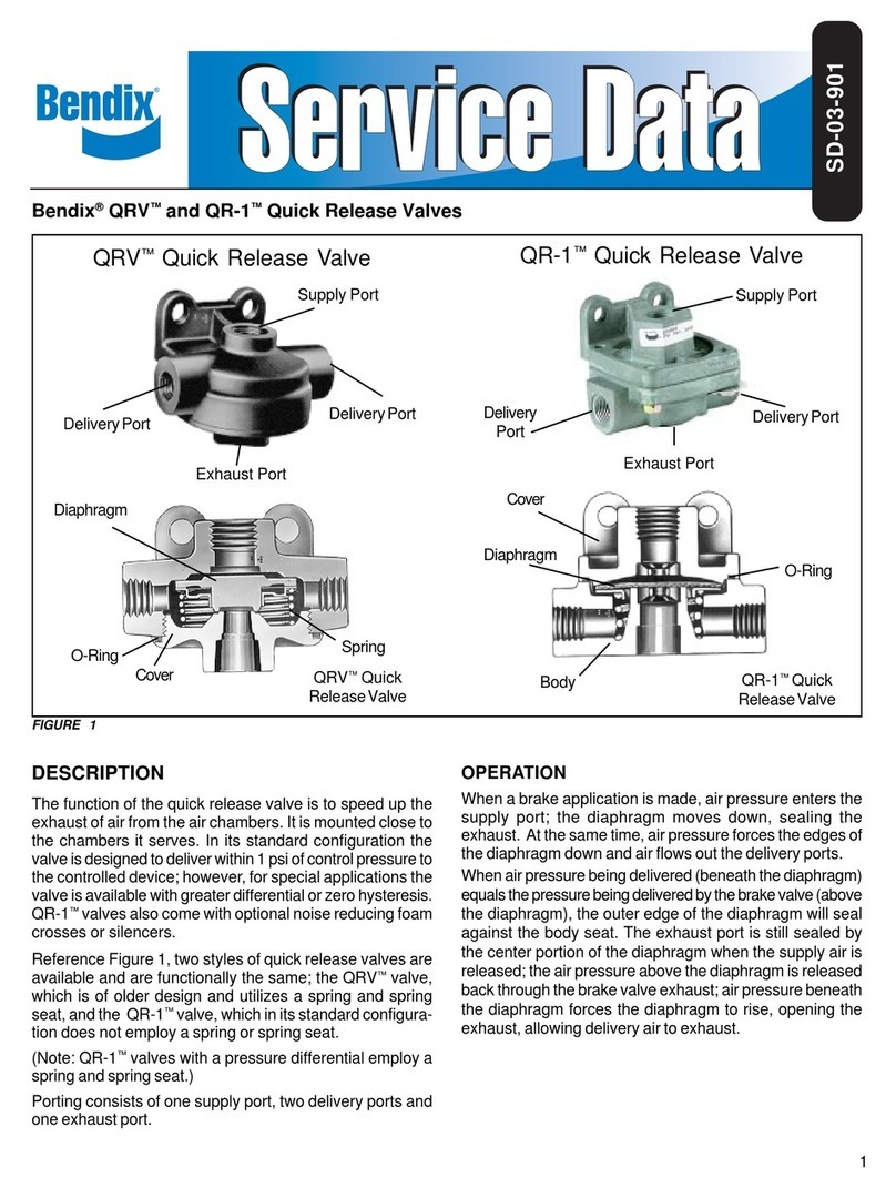
Bendix®PR-2™, PR-3™& PR-4™Pressure Protection Valves
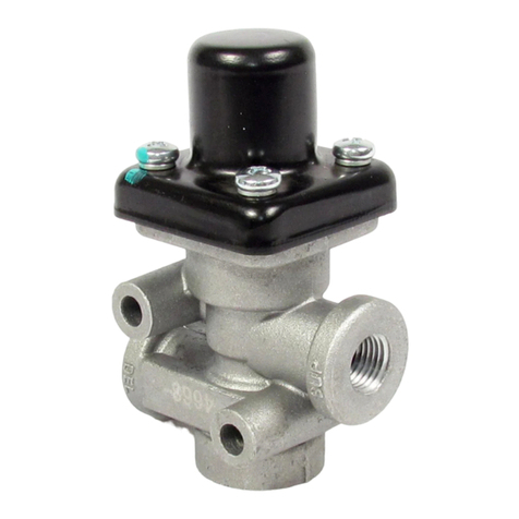
DESCRIPTION
Thepressureprotectionvalveisanormallyclosed,pressure
controlvalve whichcan bereferred toas anon-exhausting
sequence valve. These valves are used in many different
applications. An example would be in an air brake system
to protect one reservoir, or reservoir system from another,
by closing automatically at a preset pressure should a
reservoirsystemfailure occur.Thevalvescan also beused
todelayfillingofauxiliaryreservoirstoinsureaquickbuild-up
of brake system pressure.
ThePR-2™and PR-4™pressureprotectionvalveshave one
1/4"N.P.T.F.supply portand one1/4" N.P.T.F. deliveryport
whichareidentified.Bothvalvesareprovided with two 9/32"
mounting holes through the body. The closing pressure of
the PR-2™valve is externally adjustable while the PR-4™
valvehas a fixed setting.
DELIVERY
PORT
SUPPLY
PORT
PISTON
SPRING
INLET
VALVE
CAP
PR-4™PRESSURE PROTECTION VALVE
INLET
VALVE PISTON
SPRING
CHECK
VALVE
CAP
PR-3™PRESSURE PROTECTION VALVE
PR-3™OR PR-4™PRESSURE PROTECTION VALVES
INLET
VALVESPRING
INLET
VALVE
PISTON PLUG
O-RING
PRESSURE
REGULATING
SPRING
VALVESTEM
PISTON PLUG
PR-2™PRESSURE PROTECTION VALVE
EXHAUST
VENT
PISTON
O-RING
PISTON
SPRING
RETAINER
SUPPLY
PORT
DELIVERY
PORT
SUPPLY
PORT
DELIVERY
PORT
2
OPERATION
Air entering the supply port is blocked from flowing out the
deliveryportbytheinletvalve,which is normally heldclosed
by the pressure regulating spring above the piston. When
sufficientair pressurebuilds beneaththe piston,the piston
willmove,openingtheinlet valve and allowingairtoflowout
the delivery port.As long as air pressure at the supply port
remainsabovethespecifiedclosingpressure,theinletvalve
willremain open.
NOTE: The PR-2™and PR-4™valves closing pressure is
noted on the label affixed to the valve. Opening
pressures of the valves are higher than closing
pressures.Thepressure rangesarenoted below:
PR-2™valveOpeningpressure15-20psihigherthan
closingpressure.
PR-3™& PR-4™valves Opening pressure approx.
10 psi higher than closing pressure.
PR-3™valve Check valve will retain maximum
pressureindownstreamreservoir.
Ifsystemairpressuredecreasesbelowthespecifiedclosing
pressure,theregulatingspring will closetheinletvalve. The
remainingair pressureat either the supply or delivery side,
(depending on where the pressure drop occurs) will be
retained.
PREVENTIVE MAINTENANCE
Important: Review the Bendix Warranty Policy before
performinganyintrusivemaintenanceprocedures.Awarranty
maybevoided if intrusivemaintenance is performedduring
thewarrantyperiod.
No two vehicles operate under identical conditions, as a
result, maintenance intervals may vary. Experience is a
valuableguideindeterminingthe best maintenanceinterval
forairbrakesystemcomponents.Ataminimum,thePR valves
shouldbeinspectedevery6monthsor1500operatinghours,
whichevercomes first, for proper operation.Should thePR
valvesnotmeet theelementsof theoperationaltests noted
in this document, further investigation and service of the
valvemayberequired.
OPERATING AND LEAKAGE CHECKS
OPERATING CHECKS
1. Provide a pressuregauge anddrain valve atthe supply
side and delivery side of the pressure protection valve
being checked.
2. Charge the air system to full pressure and shut off the
engine.
3. Observingthegauges on the supply and delivery sides
of the valve, slowly exhaust pressure from the delivery
side.Notethatbothgauges will showpressurelossuntil
theclosing pressureof the pressure protection valve is
reached.
The pressure protection valve should close at
approximately (± 5 psi) the pressure indicated on the
valve’s label or in the vehicle handbook. The gauge on
the delivery side of the valve should continue to show
loss of pressure while the gauge on the supply side
should stop at the same pressure as the setting of the
valve.
4. (PR-3™valve only)Buildpressure upagainand shutoff
engine. Slowly exhaust air from the supply side of the
PR-3™valve.Thegaugeonthe delivery side of the valve
shouldremainatthehighestpressurepreviouslyattained.
LEAKAGECHECKS
1. Charge the air system to full pressure and shut off the
engine.
2. Apply a soap solution around the cap of the pressure
protection valve.A 1” bubble in 3 seconds or longer is
acceptable.PR-3™valve -No leakageis permissibleat
thebottom of thevalve.
3. Drain the air pressure from the delivery side of the
pressureprotection valveand disconnect the air line to
it.
4. Applyasoap solution tothe deliveryport.A1”bubble in
5 seconds or more is acceptable.
GENERAL
If the pressure protection valve does not function as
described,or leakageis excessive, it is recommendedthat
itbereplacedwith a neworremanufactured unit orrepaired
withgenuine Bendixparts availableat Bendixoutlets.
REMOVING AND INSTALLING
REMOVING
1. Blockorholdthevehiclebymeansotherthanairbrakes.
2. Drain all system reservoirs to 0 psi.
3. Disconnect and identify (supply and delivery) the air
linesleading toand fromthe pressure protection valve.
4. Remove the mounting bolts,ifany, that secure thevalve.
INSTALLING
1. Re-installthemountingboltsandsecurethereplacement
valvetothe vehicle.
2. Reconnect the supply delivery air lines to the proper
portsof the replacementvalve.
3
GENERAL
Afterinstallinga replacementvalve,it is recommendedthat
theoperatingandleakage checks beperformedasoutlined
in this manual. If the closing pressure does not conform to
thatshown onthe valvelabel orin the vehicle or a different
setting is desired, the PR-2™valve may be adjusted by
loosening the locknut and tightening or loosening the
adjusting cap as required; however, if the proper setting
cannotbe attainedby moderateadjustment of the cap, the
valve may have the wrong spring and will have to be
exchangedforthecorrectvalve.ThePR-3™andPR-4™valves
arenot adjustable.
GENERAL SAFETY GUIDELINES
WARNING! PLEASE READ AND FOLLOW
THESE INSTRUCTIONS TO AVOID
PERSONAL INJURYOR DEATH:
When working on or around a vehicle, the following
general precautions should be observed at all times.
1. Park the vehicle on a level surface, apply the
parking brakes, and always block the wheels.
Always wear safety glasses.
2. Stop the engine and remove ignition key when
working under or around the vehicle. When
working in the engine compartment, the engine
should be shut off and the ignition key should be
removed. Where circumstances require that the
enginebeinoperation,EXTREME CAUTION should
be used to prevent personal injury resulting from
contact with moving, rotating, leaking, heated or
electrically charged components.
3. Do not attempt to install, remove, disassemble or
assemble a component until you have read and
thoroughly understand the recommended
procedures. Useonly the proper tools and observe
all precautions pertaining to use of those tools.
4. If the work is being performed on the vehicle’s air
brake system, or any auxiliary pressurized air
systems,makecertainto drain the air pressure from
all reservoirs before beginning ANY work on the
vehicle. If the vehicle is equipped with an AD-IS®
air dryer system or a dryer reservoir module, be
sure to drain the purge reservoir.
5. Following the vehicle manufacturer’s
recommendedprocedures,deactivatetheelectrical
system in a manner that safely removes all
electrical power from the vehicle.
6. Never exceed manufacturer’s recommended
pressures.
7. Never connect or disconnect a hose or line
containing pressure; it may whip. Never remove a
component or plug unless you are certain all
system pressure has been depleted.
8. Use only genuine Bendix®replacement parts,
components and kits. Replacement hardware,
tubing, hose, fittings, etc. must be of equivalent
size, type and strength as original equipment and
be designed specifically for such applications and
systems.
9. Components with stripped threads or damaged
parts should be replaced rather than repaired. Do
not attempt repairs requiring machining or welding
unless specifically stated and approved by the
vehicle and component manufacturer.
10. Prior to returning the vehicle to service, make
certain all components and systems are restored
to their proper operating condition.
11. For vehicles with Antilock Traction Control (ATC),
the ATC function must be disabled (ATC indicator
lampshould be ON) prior toperforming any vehicle
maintenance where one or more wheels on a drive
axle are lifted off the ground and moving.
4BW1440 © 2006 Bendix Commercial Vehicle Systems LLC. All rights reserved. 7/2006 Printed in U.S.A.

This manual suits for next models

3

Other BENDIX Control Unit manuals

BENDIX TCS-9000 CONTROL BRAKE VALVE User manual

BENDIX

BENDIX TCS-9000 CONTROL BRAKE VALVE User manual

BENDIX PR-3 User manual

BENDIX

BENDIX PR-3 User manual

BENDIX TP-3 TRACTOR PROTECTION VALVE User manual

BENDIX

BENDIX TP-3 TRACTOR PROTECTION VALVE User manual

BENDIX AR-2 ANTILOCK RELAY VALVE User manual

BENDIX

BENDIX AR-2 ANTILOCK RELAY VALVE User manual

BENDIX R-12-R-14 RELAY VALVES User manual

BENDIX

BENDIX R-12-R-14 RELAY VALVES User manual

BENDIX QRV QR-1 QUICK RELEASE VALVES Service manual

BENDIX

BENDIX QRV QR-1 QUICK RELEASE VALVES Service manual

BENDIX TW-12 CONTROL VALVE User manual

BENDIX

BENDIX TW-12 CONTROL VALVE User manual

BENDIX E-5 BRAKE VALVE User manual

BENDIX

BENDIX E-5 BRAKE VALVE User manual

BENDIX R-8P PRESSURE EQUALIZING PILOTRELAY User guide

BENDIX

BENDIX R-8P PRESSURE EQUALIZING PILOTRELAY User guide

BENDIX ST-1 ST-3 SAFETY VALVE User manual

BENDIX

BENDIX ST-1 ST-3 SAFETY VALVE User manual

BENDIX TP-3 Mounting instructions

BENDIX

BENDIX TP-3 Mounting instructions

BENDIX TP-4 TRACTOR PROTECTION VALVE User manual

BENDIX

BENDIX TP-4 TRACTOR PROTECTION VALVE User manual

BENDIX ATR1DC ANTILOCK TRACTION RELAY User manual

BENDIX

BENDIX ATR1DC ANTILOCK TRACTION RELAY User manual

BENDIX TIM G2 User manual

BENDIX

BENDIX TIM G2 User manual

BENDIX ATR-1 ANTILOCK TRACTION RELAY User manual

BENDIX

BENDIX ATR-1 ANTILOCK TRACTION RELAY User manual

BENDIX QR-1C DBL CHECK QUICK RELEASE VALVE User manual

BENDIX

BENDIX QR-1C DBL CHECK QUICK RELEASE VALVE User manual

BENDIX TC-2 TRAILER CONTROL BRAKE VALVE User manual

BENDIX

BENDIX TC-2 TRAILER CONTROL BRAKE VALVE User manual

BENDIX TW-N TWO WAY CONTROL VALVE User manual

BENDIX

BENDIX TW-N TWO WAY CONTROL VALVE User manual

BENDIX R-12P PILOT RELAY VALVE User manual

BENDIX

BENDIX R-12P PILOT RELAY VALVE User manual

BENDIX TP-3DC TRACTOR PROTECTION VALVE User manual

BENDIX

BENDIX TP-3DC TRACTOR PROTECTION VALVE User manual

BENDIX E-10P DUAL BRAKE VALVES User manual

BENDIX

BENDIX E-10P DUAL BRAKE VALVES User manual

BENDIX TABS-6 TRAILER ABS MODULE Mounting instructions

BENDIX

BENDIX TABS-6 TRAILER ABS MODULE Mounting instructions

BENDIX AR-1 ANTILOCK RELAY VALVE User manual

BENDIX

BENDIX AR-1 ANTILOCK RELAY VALVE User manual

BENDIX RE-4 RELAY EMERGENCY VALVE User manual

BENDIX

BENDIX RE-4 RELAY EMERGENCY VALVE User manual

Popular Control Unit manuals by other brands

National Instruments NI PXI/e-4000 Series user guide

National Instruments

National Instruments NI PXI/e-4000 Series user guide

Kongsberg RSER200-4 Hardware description

Kongsberg

Kongsberg RSER200-4 Hardware description

Baker Hughes Consolidated Generation II 2900 Series instruction manual

Baker Hughes

Baker Hughes Consolidated Generation II 2900 Series instruction manual

Siemens SIMATIC ET 200SP manual

Siemens

Siemens SIMATIC ET 200SP manual

Omron CS1W-MCH71 - datasheet

Omron

Omron CS1W-MCH71 - datasheet

Omron SYSMAC C200H specification

Omron

Omron SYSMAC C200H specification

NEC LED-E012i user manual

NEC

NEC LED-E012i user manual

National Instruments IMAQ PXI-1428 user manual

National Instruments

National Instruments IMAQ PXI-1428 user manual

Sentiotec Pro B2 Instructions for installation and use

Sentiotec

Sentiotec Pro B2 Instructions for installation and use

Metasys NCM 200 Series Technical manual

Metasys

Metasys NCM 200 Series Technical manual

SEW-Eurodrive MOVISAFE DCS B Series manual

SEW-Eurodrive

SEW-Eurodrive MOVISAFE DCS B Series manual

ProFire PF3100 Series product manual

ProFire

ProFire PF3100 Series product manual

Sunsea AIoT SIMCom SIM7600NA user manual

Sunsea AIoT

Sunsea AIoT SIMCom SIM7600NA user manual

GF Piping Systems NeoFlow operating instructions

GF Piping Systems

GF Piping Systems NeoFlow operating instructions

SMART Embedded Computing RTM-ATCA-736x-10G Series Installation and use

SMART Embedded Computing

SMART Embedded Computing RTM-ATCA-736x-10G Series Installation and use

TLV P Series instruction manual

TLV

TLV P Series instruction manual

Captron CANEO 41 Series Original operating instructions

Captron

Captron CANEO 41 Series Original operating instructions

MG R3-NCIE1 instruction manual

MG

MG R3-NCIE1 instruction manual

manuals.online logo
manuals.online logoBrands
  • About & Mission
  • Contact us
  • Privacy Policy
  • Terms and Conditions

Copyright 2025 Manuals.Online. All Rights Reserved.