gAvilar gACC-499E/U User manual
gACC-499E/U
Communication Unit for Encoder/gAVC 1200
Manual
Rev. 30.05.2017
Please visit our website for the most recent version of this document www.gAvilar.nl

GA-02.035-EN-30.05.17
Page 2 of 46
gACC-499E/U Communication unit
gACC-499E_U_Manual_EN.doc
INHOUD
1. Introduction.............................................................................................................4
1.1 General............................................................................................................................................. 4
1.2 Basic construction ............................................................................................................................ 4
2. Construction ...............................................................................................................5
2.1 Build-up ............................................................................................................................................ 5
2.2 DIP-Switch........................................................................................................................................ 5
2.3 Battery connectors ........................................................................................................................... 6
2.4 Terminals intrinsically safe side ....................................................................................................... 6
2.5 Power supply.................................................................................................................................... 6
2.5.1 Battery supply .............................................................................................................................. 6
2.5.2 Mains power supply..................................................................................................................... 7
2.6 Modem Configuration....................................................................................................................... 7
2.7 The configuration IEC 62056-21...................................................................................................... 7
2.8 The readout with configuration file IEC 62056-21 for gAVC 1200................................................... 9
2.9 The readout with configuration file IEC 62056-21 for Encoder........................................................ 9
2.10 Explanation of the config file...................................................................................................... 10
2.11 The configuration program......................................................................................................... 14
2.12 Configuration read-out............................................................................................................... 15
2.13 The hidden functions.................................................................................................................. 16
2.15 Reading the archive (cache)...................................................................................................... 25
2.16 Internal caching.......................................................................................................................... 26
2.17 The Test Mode........................................................................................................................... 26
2.18 Status check............................................................................................................................... 26
3.0 Firmware update ...................................................................................................26
3.1 General........................................................................................................................................... 27
3.2 SMS update.................................................................................................................................... 27
3.3 GSM update ................................................................................................................................... 28
3.4 Local update................................................................................................................................... 28
3.5 Reset.............................................................................................................................................. 28
4.1 SIM card requirements................................................................................................................... 30
4.2 Inputs.............................................................................................................................................. 30
4.2.1 Encoder...................................................................................................................................... 30
4.2.3 Uniwire....................................................................................................................................... 30
4.2.4 Temperature (optional) .............................................................................................................. 30

GA-02.035-EN-30.05.17
Page 3 of 46
gACC-499E/U Communication unit
gACC-499E_U_Manual_EN.doc
4.2.5 Pulses ........................................................................................................................................ 30
4.3 Battery connections........................................................................................................................ 30
5.0 Installation.............................................................................................................31
5.1 Installation location......................................................................................................................... 31
5.2 Connections ................................................................................................................................... 31
5.2.1 Potential equalizing.................................................................................................................... 31
5.2.2 Signal lines and power lines ...................................................................................................... 31
5.2.3 Connections gACC-499E/U....................................................................................................... 31
5.2.4 The dividing wall ........................................................................................................................ 31
5.2.5 Inserting the SIM card................................................................................................................ 31
5.2.6 Scheme Zener Barrier................................................................................................................ 32
5.2.7Type plate .................................................................................................................................. 32
5.3 Repairs........................................................................................................................................... 33
5.4 The absorption pack....................................................................................................................... 33
5.5 Pressure relief valve....................................................................................................................... 33
6.0 The clock ...............................................................................................................34
6.1 Setting time locally ......................................................................................................................... 34
6.2 Setting time remotely...................................................................................................................... 34
6.3 Setting time using the IEC62056-21 protocol. ............................................................................... 36
7.0 Meter exchange.....................................................................................................37
7.1 Gas meter exchange...................................................................................................................... 37
7.2 gAVC 1200 exchange .................................................................................................................... 37
7.3 Battery exchange ........................................................................................................................... 38
7.4 Cache Reset................................................................................................................................... 38
8.0 EC-Type Examination Certificate.........................................................................40
9.0 Declaration of conformity.....................................................................................45

GA-02.035-EN-30.05.17
Page 4 of 46
gACC-499E/U Communication unit
gACC-499E_U_Manual_EN.doc
1. Introduction
1.1 General
The gACC-499E/U is specially developed for the so-called SME segment where the used gas meters or
gAVC 1200 can be read remotely to retrieve the actual meter readings. Essential is the use of optical
encoders with a NAMUR communication output. As a result, it is possible to perform a cyclic read-out of the
index value by using the IEC62056-21 protocol. Other communication methods are available on request. The
gACC-499E/U is available in mains power supply and battery power supply. The mains power supply version
can be used for short measuring cycles and frequently used communication, e.g. for feeding a web portal.
The battery power supply version is suitable for daily, weekly or monthly communication modes. In daily
communication, with good network coverage, the battery life span (2pack) will be approx. 6 years.
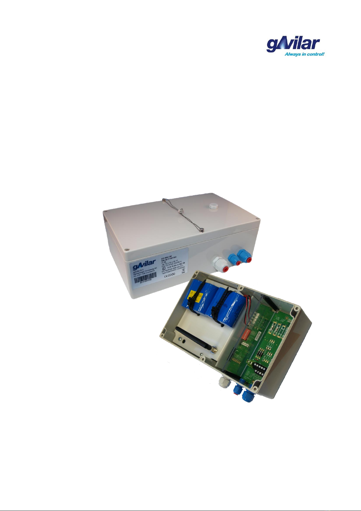
1.2 Basic construction
The modem gACC-499E/U consist of 2 main compartments whereby the largest compartment is equipped
with a mainboard on which the power supply terminals, inputs and the TC-65i or TC-65ix module carrier are
placed. The smaller compartment contains a multi-channel Zener barrier which complies with the ATEX
directive 94/9/EC for all possible input signals. The compartments are separated by a removable dividing
wall.
The Zener barrier EX-499-UW complies with an associated intrinsically safe apparatus in the form of a max.
5-channel Zener barrier. The number of channels depends on the application.
Normally the device is supplied completely configured, whereby the SIM card can be placed if requested by
the customer. The connection of the unsafe side is at the top of the Zener barrier performed by a plug
connection. The intrinsically safe outputs and terminals for the potential equalizing are located at the bottom,
so in the standard version in the terminal compartment of the housing.
The gACC-499E/U can be used for several applications whereby it can operate as a stand-alone data logger
for e.g. index readings of a gas meter with a NAMUR encoder, a simple pulse generator or as
communication unit for the gAVC 1200. For every application a specific configuration file is necessary. By
using an 8-pole DIP switch the device can be set to the desired application. Time windows can be applied to
let the gACC-499E/U login to the net at fixed intervals. After that there can be dialed-in by using a data
collection system. These settings are stored in a XML-file in the memory of the gACC-499E/U.
By using the gACC-499E/U in combination with an gAVC 1200 there will be a protocol conversion from
MODBUS RTU to IEC62056-21 performed. The specific settings of the gAVC 1200 can be performed in a
transparent mode via the gACC-499E/U. The configuration program of the gAVC 1200 can make a
transparent connection by using a modem, whereby all the parameters can be read. With the availability of
metrological rights all parameters can also be programmed.
The gACC-499 E/U can communicate data via the IEC62056-21 protocol where 3 main functions are
supported.
1. Billing data,
2. Load profile data
3 Time synchronization.
For this protocol is a separate detailed protocol description available (gAVC_1200_IEC62056-21.pdf). In
addition an access password (P1) can be used to prevent unwanted connections with measurement.

GA-02.035-EN-30.05.17
Page 5 of 46
gACC-499E/U Communication unit
gACC-499E_U_Manual_EN.doc
2. Construction
2.1 Build-up
2.2 DIP-Switch
No.
Function
1 - On/Off
ON = Operating mode
Should be switched ON at normal operating mode!!
2 - No Sleep
ON = Disable sleep mode, the device will not go to sleep.
Should be switched OFF at battery operating mode!!
3 - LEDs On
ON = Status display on.
Should be switched OFF at battery operating mode!!
4 - Test mode
ON = Activate test mode
Should be switched OFF at normal operating mode!!
5 - Config 1
ON = Encoder operating mode
OFF = gAVC 1200 operating mode
6 - Config 2
Can be used to activate Log Level 0. This function can only be activated by
restarting the device after setting the switch.
7 - Encoder On
ON = Interface gAVC 1200 or Encoder on.
Should be switched ON at normal operating mode!!
8 - MU Power
ON = Power supply to EVCD enabled. (By externally powered EVCD)
Should be switched OFF at battery operating mode!!
PA-Klemmen
Antenna connection
Connector USB
configuration cable
DIP-Switch
(See below for
description)
Status display (LED)
SIM card
Terminals intrinsically
safe side. ( For
connection details see
below)
PA-Terminals
Removable dividing
wall
Battery connector 2.1
Battery connector 1.1
Fuse power supply
EVCD (mains power
supply only)

GA-02.035-EN-30.05.17
Page 6 of 46
gACC-499E/U Communication unit
gACC-499E_U_Manual_EN.doc
DIP switch function: Active at position ON
All switches are in OFF position at delivery,
xcept for DIP switch 7. This will save energy of the batteries.
The internal clock will keep running at normal operating mode.
2.3 Battery connectors
The gACC-499 E/U is equiped with 6 battery connectors.
These are divided into 2 groups.
MAIN POWER
Group1: Connector 1.1; 1,2; 1,3 and 1,4 Main Power
RESERVE POWER
Group 2: Connector 2.1; and 2.2 Back-up and clock power
When applying 2 battery packs, connector 1.1 is used for main
power, and 2.2 is used for back-up.
2.4 Terminals intrinsically safe side
Terminal EX-499-UW
Function
1 GND
Signal line -
2 Encoder signal
Signal line +
3 GND
Signal line gAVC 1200 XP2 terminal B
4 UniWire
Signal line gAVC 1200 XP2 terminal A
9 GND
Signal line - (only possible with Safety Barrier channel 4)
10 Pulse signal
Signal line + (only possible with Safety Barrier channel 4)
Connection Encoder or gAVC 1200 or Pulse
Encoder
gAVC 1200
Puls
1 NAMUR (-)
3 UniWire B (klem XP2)
9 GND
2 NAMUR (+)
4 UniWire A (klem XP2)
10 Pulse signal
The PA-terminals are to be connected to the PA-connection of the installation.
This can be done by using 4mm2yellow/green wire or by using 2 wires of
1,5mm2.
2.5 Power supply
2.5.1 Battery supply
The standard battery supply consists of 2 identical battery packs with each
pack containing 2 Lithium batteries connected in series. The operating
voltage is 7,2 Vdc. The battery pack that is connected to connector 1.1 will
be used first for the modem and the battery pack that is connected to
connector 2.2 will be used for the internal clock. After pack 1.1 is
consumed it will switch to pack 2.2. For certain applications additional
battery packs can be applied. These will be connected to connectors 1.2;
1.3 and/or 1.4.
An additional pack can be connected to connector 2.1 for extended back-
up.
Warning: Always use batteries of the same type
DIP switch
Battery connectors
PA terminals

GA-02.035-EN-30.05.17
Page 7 of 46
gACC-499E/U Communication unit
gACC-499E_U_Manual_EN.doc
When replacing battery packs in a normal operating state, a new battery pack can be connected to an
available connector, before removing the already placed battery packs. If the battery packs are totally
consumed and the device is no longer in operation mode, remove the empty packs before placing new
battery packs. When inserting new battery packs, always connect the first battery pack to Group 1 (e.g.
connector 1.1) and the second battery pack to Group 2 (e.g. 2.2). Do not forget to set the clock. (see chapter
6.0 The clock for setting the clock.)
2.5.2 Mains power supply
The power supply consists of a power module with an operating voltage
of 7,2Vdc. De power supply will be connected to Group 1 (e.g. connector
1.1). If required, a back-up battery can be connected to Group 2 (e.g.
connector 2.2).
The power supply module is equiped with a IEC mains power connector.
The supply of voltage of 85Vac to 230Vac can be connected to this.
The housing of the device is equiped with an additional cable gland.
Once the gACC-499E/U is provided with mains power an optionally
connected EVCD from Flonidan (gAVC 1200) can also be powered.
The supply voltage is 4Vdc and intrinsically conducted.
2.6 Modem Configuration
The configuration of the required information can be done by using a simple XML file which determines
which data in which format should be sent. This requires a configuration program which can be used to
configure the modem locally and remotely. For local configuration of the modem a special USB-config cable
is available.
2.7 The configuration IEC 62056-21
To read-out the gAVC 1200 with the IEC62056-21 protocol a special configuration file is required which
contains specified settings for the protocol. The configuration file is written into the modem. The settings for
the provider are limited to the name of that provider and for GPRS-connection also the APN-data. Instead of
the name of the provider, “home” may also be entered. This sets the provider of the used SIM-card as
default provider which excludes roaming into other networks. The server type must be set to LOCAL.
Please note the protocol settings for the gAVC 1200. It must always remain at 2400 Baud and 8N1 to
communicate with an encoder or an gAVC 1200.
It is also possible to configure the gACC-499E/U remotely by using the configuration program in combination
with a local modem. For this, the corresponding COM-port must be selected. By entering a modem init string
e.g. AT&FX1&K0DT the program knows that it should dial the number that has been entered at “Phone
number” via a modem. For local communication there should not be a modem init string entered.
GA-02.035-EN-30.05.17
Page 8 of 46
gACC-499E/U Communication unit
gACC-499E_U_Manual_EN.doc
By clicking the symbol in the left upper corner a window will open which contains the special functions of the
program. At “Set Value” the index value of the pulse counter can be set to a start value (meter
synchronization) or to be reset. The “Name” must be entered as VB and the value as a decimal number.
The pre-setting of the index value can be done by using a config cable. If the modem is in “sleep” mode the
config cable must be plugged in the socket in order to activate it.
The modem will now come out sleep mode and will become active. At least 3 LEDs have to be on before a
value can be written. For battery modems this can be done by setting DIP switch 3 to ON. Make sure that
DIP-switch 3 is back in the OFF position before placing the cover. This is to save battery power.
The gACC-499E/U is equipped with a selection switch for the configuration. With DIP-switch 5 (to OFF) can
be chosen between the gAVC1200 application and (to ON) the Encoder application.
These functions will be described in more detail in chapter 2.13 The hidden functions.

GA-02.035-EN-30.05.17
Page 9 of 46
gACC-499E/U Communication unit
gACC-499E_U_Manual_EN.doc
2.8 The readout with configuration file IEC 62056-21 for gAVC 1200
An example of the config file for IEC62056-21:
<configuration>
<dual1>
<swversion req="2.01"/>
<general confversion="1" loglevelstdout="3" checkpwdlocal="y" readcfgallowed="n" sleepallowed="y" battlifeoffset="6"
dualmainbatt="n" otapurl="http://www.gasdatawarehouse.de/GprsUpdate/ClkGprs.jad"/>
<reset hour="17" minute="30" daylight="y"/>
<device name="gprs003" type="gAVC" key="UF1200L3" timesync="Y" fullsynctimediff="y" alarmlog="Y"
monthlog="Y" params="DevIdent=U1200_" modbusaddress="0" noonlinevalues="y" startupcachedays="2" >
</device>
<protocol type="iec62056-21" daylight="N" billingdaylight="Y" password="Y">
<archivechannel identifier="23.2.0" valuetype="VN" multiplier="1" unit="m3"/>
<archivechannel identifier="1:12.0.0" valuetype="SVB" multiplier="1" unit="m3"/>
<archivechannel identifier="13.1.0" valuetype="VB" multiplier="1" unit="m3"/>
<archivechannel identifier="1:13.0.0" valuetype="VBZ" multiplier="1" unit="m3"/>
<archivechannel identifier="0:41.0.0" valuetype="T" multiplier="10" unit="K"/>
<archivechannel identifier="0:42.0.0" valuetype="PABS" multiplier="1000" unit="mbar"/>
<archivechannel identifier="97.97.0" valuetype="ALRACT1" multiplier="1" unit=""/>
<billingchannel identifier="1:13.0.0" valuetype="VBZ" multiplier="1" unit="m3"/>
<billingchannel identifier="13.1.0" valuetype="VB" multiplier="1" unit="m3"/>
<billingchannel identifier="23.2.0" valuetype="VN" multiplier="1" unit="m3"/>
<billingchannel identifier="1:12.0.0" valuetype="SVB" multiplier="1" unit="m3"/>
<billingchannel identifier="0:41.0.0" valuetype="T" multiplier="10" unit="K"/>
<billingchannel identifier="0:42.0.0" valuetype="PABS" multiplier="1000" unit="mbar"/>
<billingchannel identifier="7-1:0.2.14" valuetype="FabNo" multiplier="1" unit=""/>
<billingchannel identifier="C.91.10" valuetype="Herst" multiplier="1" unit=""/>
<billingchannel identifier="C.91.11" valuetype="HerstJahr" multiplier="1" unit=""/>
<billingchannel identifier="97.97.0" valuetype="ALRACT1" multiplier="1" unit=""/>
<billingchannel identifier="1:13.0.0" valuetype="VBZlastMonth" multiplier="1" unit="m3"/>
<billingchannel identifier="23.2.0" valuetype="VNlastMonth" multiplier="1" unit="m3"/>
</protocol>
<uptime hourstart="18" minutestart="00" minutesduration="30" upaftercallin="5" daylight="y" NoIntermediateGSM="n" />
</dual1>
2.9 The readout with configuration file IEC 62056-21 for Encoder
<dual2>
<swversion req="2.01"/>
<general confversion="1" loglevelstdout="3" checkpwdlocal="y" readcfgallowed="n" sleepallowed="Y"
battlifeoffset="6" dualmainbatt="n" otapurl="http://www.gasdatawarehouse.de/GprsUpdate/ClkGprs.jad"/>
<reset hour="17" minute="30" daylight="y"/>
<device name="gprs003" type="CLKTENC" timesync="Y" clearonstartup="N" log_interval="60"
archive_config="T,ENC,IMP" persistentdata="n" params="DevIdent=U1200_">
</device>
<protocol type="iec62056-21" daylight="n" billingdaylight="Y" password="Y">
<archivechannel identifier="23.2.0" valuetype="VN" multiplier="1" unit="m3"/>
<archivechannel identifier="1:12.0.0" valuetype="SVB" multiplier="1" unit="m3"/>
<archivechannel identifier="1:13.1.0" valuetype="VB" multiplier="1" unit="m3"/>
<archivechannel identifier="1:13.0.0" valuetype="VO" multiplier="1" unit="m3"/>
<archivechannel identifier="0:41.0.0" valuetype="T" multiplier="10" unit="K"/>
<archivechannel identifier="0:42.0.0" valuetype="PABS" multiplier="1000" unit="mbar"/>
<archivechannel identifier="97.97.0" valuetype="ALR1" multiplier="1" unit=""/>
<billingchannel identifier="1:13.0.0" valuetype="VO" multiplier="1" unit="m3"/>
<billingchannel identifier="C.91.10" valuetype="Herst" multiplier="1" unit=""/>
<billingchannel identifier="7-1:0.2.14" valuetype="FabNo" multiplier="1" unit=""/>
<billingchannel identifier="C.91.11" valuetype="HerstJahr" multiplier="1" unit=""/>
<billingchannel identifier="97.97.0" valuetype="ALR1" multiplier="1" unit=""/>
<billingchannel identifier="1:13.0.0" valuetype="VBZlastMonth" multiplier="1" unit="m3"/>
</protocol>
<uptime daystart="01" hourstart="18" minutestart="00" minutesduration="120" upaftercallin="5" daylight="y"/>
<uptime daystart="04" hourstart="18" minutestart="00" minutesduration="120" upaftercallin="5" daylight="y"/>
<uptime daystart="07" hourstart="18" minutestart="00" minutesduration="120" upaftercallin="5" daylight="y"/>
</dual2>
GA-02.035-EN-30.05.17
Page 10 of 46
gACC-499E/U Communication unit
gACC-499E_U_Manual_EN.doc
</configuration>
2.10 Explanation of the config file
configuration
Open configuration file.
dual1
Here begins the first block of the configuration (DIP-switch 5 to ON)
swversion req=”2.01”
Minimum software version in the gACC-499E/U for this application
general
confversion=”1”
This is the current configuration version. This can be increased by 1, and then with the
next data transmission the available data in the current interval will be sent.
loglevelstdout=3”
Specifies the level of logging. 0 is the highest level and 3 is the lowest level. A choice can
be made between 0, 1, 2 and 3. During normal operation level “3” is selected. This is only
used for communication analysis .
checkpwdlocal=”Y”
Enter =”N” or “Y”. N is the choice of not applying a password. When Y is entered, a
password is used to gain access to the gACC-499E/U.
readcfgallowed=N”
Enter =”N” or “Y”. Y allows reading of the configuration and when N is entered, it’s not
possible to read the configuration without a password
sleepallowed=”Y”
Enter “N” or “Y”. For battery powered devices the “sleep” mode can be suppressed for a
fixed time. This affects the battery life span.
battlifeoffset=”6”
This determines the number of months on which a low battery warning will appear before
the end of the calculated life span of the batteries. 0/12 can be entered
dualmainbatt=”N”
In case of application of a battery at Bat2 and Bat3 here should be an ”Y” entered.
otapurl=
http://www.gasdatawarehouse.de/GprsUpdate/ClkGprs.jad Here is the update path (URL)
specified for automatic updates..
<reset hour="17"
minute="30"/>
daylight=”Y”
With mains powered or permanent powered modems an automatic reset must be
performed daily.. The time is entered at reset hour. This should preferably be done shortly
before the read-out takes place, in order to have the cache complete during read-out. The
daylight parameter ensures that summertime is applied.
device
The type of device is opened.
name=”gprs003”
The name of the device.
type=”gAVC”
This is the type of modem set for a gAVC 1200
key_”789”
The “key” is the password of the gAVC 1200 for writing data.
timesync=”Y”
Time synchronization is disabled or with “Y” enabled.
fullsynctimediff=”Y”
With fullsynctimediff=”Y” unlimited time changes can be made. With “N” this is max. 10
seconds.
alarmlog=”Y”
With Alarmlog=”Y” all the alarm status information of the gAVC 1200 will be saved in the
cache memory.
monthlog=”N”
With monthlog=”N” no information of the Month logger of the gAVC 1200 will be saved in
the cache memory. With “Y” it will be saved in the cache memory.
params= “DevIdent
=U1200_”
The identity of the device can be determined in the config. In many cases this will be
U1200_ in which after the identity the serial number of the device is transmitted. For
certain AMR systems FLO5UF12345678 will be used in which 12345678 is the serial
number the device.
modbusaddress=”0”
In some applications it is possible to communicate with 2 gAVC’s. The master MODBUS
address is 0 and the slave is 1. For a single gAVC this must always be 0.
noonlinevalues=Y”
For fast communication without internal data is being communicated this parameter is set
to ”Y”. If it’s necessary to always have the latest information read from the gAVC this
parameter can be set to “N”.
startupcachedays=”
2”
At commissioning of a new device with an empty cache can be cached up to the maximum
number of days entered. If a gAVC is already operating for several weeks or months, it is
possible that the memory is already quite full. To prevent that the caching will take long
(approx. 30 min.) a restriction can be applied.
/device
The device is closed.
protocol
The used protocol is opened.
type=”iec62056-21”
The type is IEC 62056-21 before IEC1107
daylight=”N”
Summertime is disabled or with “Y” enabled. The device operates throughout the year in
wintertime.
billingdaylight=”Y”
The index end of month will be displayed on the first of the month at 06:00 local time
password=”Y”
A P1 password is used by the IEC62056-21 protocol
GA-02.035-EN-30.05.17
Page 11 of 46
gACC-499E/U Communication unit
gACC-499E_U_Manual_EN.doc
Channel
OBIS code
Parameter
Factor
Unit
A1
23.2.0
VN
Volume converted
1
m3
A2
1:12.0.0
SVB
Vol. measured at error
1
m3
A3
13.1.0
VB
Volume measured
1
m3
A4
1:13.0.0
VBZ
Volume Encoder
1
m3
A5
0:41.0.0
T
Gas temperature
10
K
A6
0:42.0.0
PABS
Pressure gas
1000
mbar
A7
97.97.0
ALRACT1
Status information* gAVC1200
1
-
B1
1:13.0.0
VBZ
Volume Encoder
1
m3
B2
13.1.0
VB
Volume measured
1
m3
B3
23.2.0
VN
Volume converted
1
m3
B4
1:12.0.0
SVB
Vol. measured at error
1
m3
B5
0:41.0.0
T
Gas temperature
10
K
B6
0:42.0.0
PABS
Pressure gas
1000
mbar
B7
7-1:0.2.14
FabNo
Serial no. gas meter
1
-
B8
C.91.10
Herst
Manufacturer gas meter
1
-
B9
C.91.11
HerstJahr
Year of built gas meter
1
-
B10
97.97.0
ALRACT1
Status information* gAVC 1200
1
-
B11
1:13.0.0
VBZlastmonth
Vb index end of month 06:00 hour
1
m3
B12
23.2.0
VNlastmonth
Vn index end of month 06:00 hour
1
m3
* The status information of the gAVC 1200 concerns the current status information.
The units for temperature and pressure can be adjusted from K and mbar to C and bar.
The IEC62056-21 will be automatically adjusted after changes the units.
Channel
OBIS code
Parameter
Factor
Unit
A5
0:41.0.0
T
Gas temperature
1
C
A6
0:42.0.0
PABS
Gas pressure
1
bar
B5
0:41.0.0
T
Gas temperature
1
C
B6
0:42.0.0
PABS
Gas pressure
1
bar
/protocol
End of protocol. The order of the channels is defined in the table above.
uptime
hourstart="18"
minutestart="00" (at 18:00 hours the modem is switched on)
minutesduration="30" (The modem stays switched on for 30 minutes before dial-in)
upaftercallin="5" (After disconnecting the modems stays switched on for 5 minutes)
Note: The time set at “minutesduration’ can never be exceeded by “upaftercallin”
daylight="Y" (Summertime is enabled, with “N” it’s disabled
NoIntermediateGSM=”N” The TC65i module is enabled for data communication, with “Y”
only the internal measuring data will be moved to the system memory.
/dual1
End of the first block of the config file.
GA-02.035-EN-30.05.17
Page 12 of 46
gACC-499E/U Communication unit
gACC-499E_U_Manual_EN.doc
dual2
Here begins the second block of the configuration (DIP-switch 5 to OFF)
swversion req=”2.01”
Minimum software version in the gACC-499E/U for this application
general
confversion=”1”
This is the current configuration version. This can be increased by 1, and then with the
next data transmission the available data in the current interval will be sent.
loglevelstdout=3”
Specifies the level of logging. 0 is the highest level and 3 is the lowest level. A choice can
be made between 0, 1, 2 and 3. During normal operation level “3” is selected. This is only
used for communication analysis .
checkpwdlocal=”Y”
Enter =”N” or “Y”. N is the choice of not applying a password. When Y is entered, a
password is used to gain access to the gACC-499E/U.
readcfgallowed=N”
Enter =”N” or “Y”. Y allows reading of the configuration and when N is entered, it’s not
possible to read the configuration without a password
sleepallowed=”Y”
Enter “N” or “Y”. For battery powered devices the “sleep” mode can be suppressed for a
fixed time. This affects the battery life span.
battlifeoffset=”6”
This determines the number of months on which a low battery warning will appear before
the end of the calculated life span of the batteries. 0/12 can be entered
dualmainbatt=”N”
In case of application of a battery at Bat2 and Bat3 a ”Y” must be entered.
otapurl=
http://www.gasdatawarehouse.de/GprsUpdate/ClkGprs.jad Here is the update path (URL)
specified for automatic updates.
<reset hour="17"
minute="30"/>
daylight=”Y”
With mains powered or permanent powered modems an automatic reset must be
performed daily.. The time is entered at reset hour. This should preferably be done shortly
before the read-out takes place, in order to have the cache complete during read-out. The
daylight parameter ensures that summertime is applied.
device
The type of device is opened.
name=”gprs003”
The name of the device.
type=”CLKTENC”
This is the type of modem set for a encoder, temperature and pulse
timesync=”Y”
Time synchronization is disabled or with “Y” enabled.
fullsynctimediff=”Y”
With fullsynctimediff=”Y” unlimited time changes can be made. With “N” this is max. 10
seconds.
clearonstartup=”N”
During start-up of the modem all stored data will be deleted from the cache memory.
log_interval=”60”
The selected parameters will be archived with an interval of “60” minutes. Hourly values
are indicated with “60”.
archive_config=
”T,ENC,IMP”
For the here entered parameters Temperature, Encoder and Pulse a measurement must
be created. In the omission of a measurement the corresponding parameter must also be
omitted. T stands for Temperature, ENC for encoder and IMP for Pulses.
persistentdata=”N”
Persistent data “Y” indicates that the data remains intact and archived in such a way that
it will be available on a later date/time. This is for the ECG-499E/U not necessary.
params= “DevIdent
=U1200_”
The identity of the device can be determined in the config. In many cases this will be
U1200_ in which after the identity the serial number of the device is transmitted. For
certain AMR systems FLO5UF12345678 will be used in which 12345678 is the serial
number the device.
/device
The device is closed.
protocol
The used protocol is opened.
type=”iec62056-21”
The type is IEC 62056-21 before IEC1107
daylight=”N”
Summertime is disabled or with “Y” enabled. The device operates throughout the year in
wintertime.
billingdaylight=”Y”
The index end of month will be displayed on the first of the month at 06:00 local time
password=”Y”
A P1 password is used by the IEC62056-21 protocol

GA-02.035-EN-30.05.17
Page 13 of 46
gACC-499E/U Communication unit
gACC-499E_U_Manual_EN.doc
Note: The input of parameters is not case sensitive. For example “y” or “Y” can be applied.
In determining times for the call windows the start-up time of the gACC-499E/U should be taken in to
consideration. It will take approx. 3 minutes before a dial-in can be performed.
Channel
OBIS code
Parameter
Factor
Unit
A1
23.2.0
VN
Volume converted
1
m3
A2
1:12.0.0
SVB
Vol. measured at error
1
m3
A3
13.1.0
VB
Vol. measured
1
m3
A4
1:13.0.0
VO
Volume Encoder
1
m3
A5
0:41.0.0
T
Gas temperature
10
K
A6
0:42.0.0
PABS
Pressure gas
1000
mbar
A7
97.97.0
ALR1
Status information* gAVC1200
1
-
B1
1:13.0.0
VO
Volume Encoder
1
m3
B2
C.91.10
Herst
Manufacturer gas meter
1
-
B3
7-1:0.2.14
FabNo
Serial no. gas meter
1
-
B4
C.91.11
HerstJahr
Year of built gas meter
1
-
B5
97.97.0
ALR1
Status information* gAVC 1200
1
-
B6
1:13.0.0
VBZlastmonth
Vb index end of month 06:00 hour
1
m3
The units for temperature and pressure can be adjusted from K and mbar to C and bar.
The IEC62056-21 will be automatically adjusted after changes the units.
This is irrelevant for the encoder application because there are no meter readings.
Channel
OBIS code
Parameter
Factor
Unit
A5
0:41.0.0
T
Gas temperature
1
C
A6
0:42.0.0
PABS
Gas pressure
1
bar
B5
0:41.0.0
T
Gas temperature
1
C
B6
0:42.0.0
PABS
Gas pressure
1
bar
/protocol
End of protocol. The order of the channels is defined in the table above.
uptime
hourstart="18"
minutestart="00" (at 18:00 hours the modem is switched on)
minutesduration="120" (The modem stays switched on for 120 minutes before dial-in)
upaftercallin="5" (After disconnecting the modems stays switched on for 5 minutes)
Note: The time set at “minutesduration’ can never be exceeded by “upaftercallin”
daylight="Y" (Summertime is enabled, with “N” it’s disabled
NoIntermediateGSM=”N” The TC65i module is enabled for data communication, with “Y”
only the internal measuring data will be moved to the system memory.
/dual2
End of the second block of the config file.
</configuration>
Close configuration file

GA-02.035-EN-30.05.17
Page 14 of 46
gACC-499E/U Communication unit
gACC-499E_U_Manual_EN.doc
2.11 The configuration program
Modem
Com-port setting
Baud rate should always be
2400. The password applies to
the configuration.
The phone number is applied
to the used SIM-card.
The modem init string is
required when connecting via a
modem. When using a config
cable this field should be left
empty.
The data format has to be set
to 8n1 and the checkbox
Config adapter must be ticked.
With Reset pw the Config
password can be reset. This
requires the existing password.
Mobile network
Enter operator and when
required a PIN.
For GPRS connection enter an
APN. The server socket is
used in case of a GPRS socket
connection.
With “home” the provider of the
placed SIM-card is used as
default.
Server 1
The password is the P1
password for IEC62056-21
communication. The server
type must always be set to
LOCAL.
For GSM communication it’s
not allowed to enter a NTP-
server
With “Read” the configuration
is read form the gACC and
with “Write configuration into
the modem” the configuration
is written into the modem.
Password must be entered
when required.

GA-02.035-EN-30.05.17
Page 15 of 46
gACC-499E/U Communication unit
gACC-499E_U_Manual_EN.doc
2.12 Configuration read-out
Reading out the configuration and configuration file can be performed by using a config cable or through a
modem connection. In case a password is required for reading out the configuration and configuration file
this can be entered at the “Password” field (below the “Baud rate” field). The activation of the password is
arranged in the configuration file. During read-out the user will be prompted whether to save the
configuration file or not.
At the end of the read-out the below dialog appears.
This dialog shows:
a. The field strength in dB
b. Software version and compilation date
c. Device time (current time)
d. TC65 version number
e. The setting of the DIP-switches (x = not linked to CPU; 0 = OFF and 1= ON)
f. IMEI number of the TC65 (This number can be copied to the clipboard for further processing.
This can be used to find the modem serial number in the list.)
GA-02.035-EN-30.05.17
Page 16 of 46
gACC-499E/U Communication unit
gACC-499E_U_Manual_EN.doc
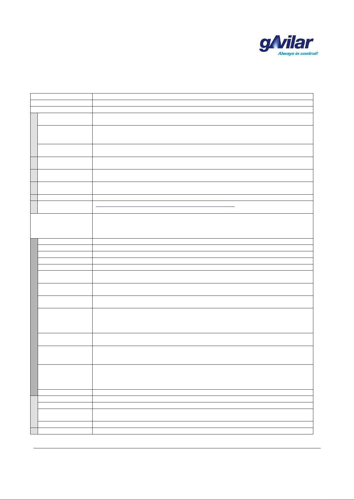
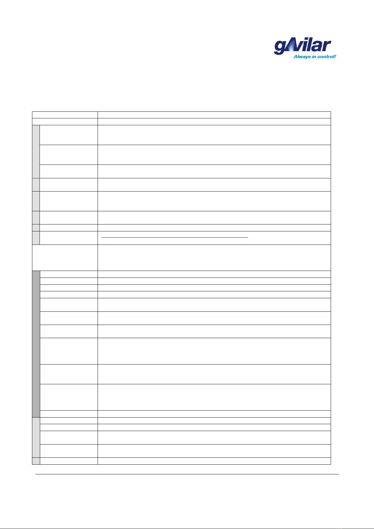
2.13 The hidden functions
The configuration program of the gACC-499 has some hidden functions. The hidden functions can be used
by clicking on the icon in the left corner of the configuration program. The here shown functions can be
executed both locally by using a config cable and also remotely via a modem.
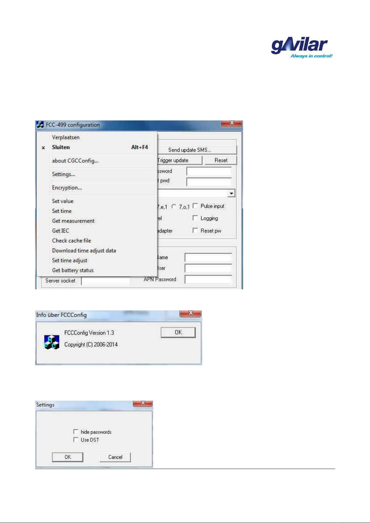
“about GACCconfig....”
Under “Settings” there is a dialogue in which a choice can be made to hide the passwords and to activate
summer / winter transitions.. This last function only affects the local readout of the cache memory of the
gACC-499E/U.
GA-02.035-EN-30.05.17
Page 17 of 46
gACC-499E/U Communication unit
gACC-499E_U_Manual_EN.doc
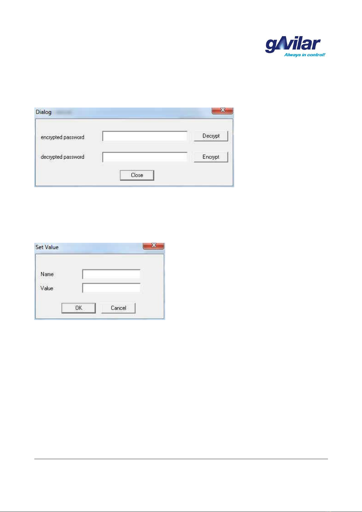
Encryption
Under “Encryption” there is a dialogue where the passwords can be encrypted and/or decrypted.
Set value
At “Set value” a pre-set index value can be entered for the logging of impulses of e.g. a gas meter. With this
function the index value of the gas meter can be synchronized with the commissioning of
the gACC-499E/U
Set time
At “Set time” the time of the connected PC can be written in the gACC-499E/U. It is important to check if the
time of the PC is the correct time before this is written into the gACC-499E/U. For more clock settings see
chapter 6..

GA-02.035-EN-30.05.17
Page 18 of 46
gACC-499E/U Communication unit
gACC-499E_U_Manual_EN.doc
Get measurement (Encoder)
At “Get measurement” can be checked, in case of direct communication with an encoder, if the encoder
function is operating correctly. Both A-telegram and B-telegram are read..
The index value of the gas meter
The information of the B-telegram

GA-02.035-EN-30.05.17
Page 19 of 46
gACC-499E/U Communication unit
gACC-499E_U_Manual_EN.doc
Get measurement (gAVC 1200)
At “Get measurement” can be checked, in case of direct communication with an gAVC 1200, if the
communication with the gAVC 1200 is functioning correctly. The clock of the gAVC 1200 is read and when
the UniWire is connected correctly it will reply with an Init OK. Also the B-telegram of the connected gas
meter will be read..
37 bytees are read
The communication with the gAVC is OK
The information of the B-telegram
GA-02.035-EN-30.05.17
Page 20 of 46
gACC-499E/U Communication unit
gACC-499E_U_Manual_EN.doc
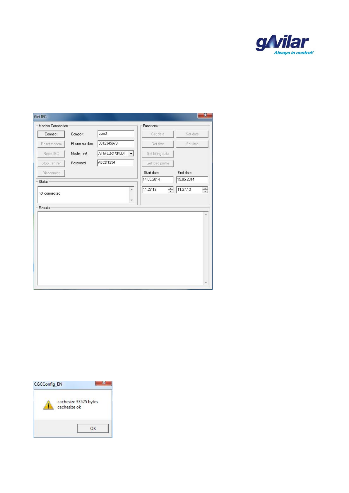
IEC622056-21 Communication
With the configuration program it is possible to communicate through the IEC62056-21 protocol by using a
modem connection. In order to do this select “Start IEC” from the menu. The COM-port for the modem needs
to be set, a phone number must be entered and a modem init string must be specified.
At “Status” the status of the communication is continuously displayed as well as the ICT (Inter Character
Time).
At “Functions” the date can be read and/or set, de time can be read and/or set, billing data can be retrieved
and an interval for a load profile can be set in order to read it afterwards. The default interval which is
displayed by the configuration program is always the latest current day. The program locks the buttons while
performing the last chosen action. This will prevent that the current processes will conflict with eachother.
In the window “Results” the communication will be displayed.
Control cache file
With "Control Cache File" can be checked whether the cache is properly created and also displays the file
size.
Table of contents


