SST GT200-3HT-MT User manual

3-channel HART/Modbus TCP Gateway
GT200-3HT-MT
User Manual
V 3.1
SST Automation
Email: [email protected]
www.SSTAutomation.com

User Manual
3-channel HART/Modbus TCP Gateway
GT 200-3HT-MT
www.SSTAutomation.com 2
Catalog
1 Product Overview ......................................................................................................................................................4
1.1 Product Function ............................................................................................................................................ 4
1.2 Product Features .............................................................................................................................................4
1.3 Technical Specifications .................................................................................................................................4
1.4 Related Products .............................................................................................................................................5
1.5 Revision History .............................................................................................................................................5
2 Quick Start Guide ...................................................................................................................................................... 6
2.1 Configuration of Gateway ..............................................................................................................................6
2.1.1 Connection Settings ............................................................................................................................ 6
2.1.2 Software Configuration .......................................................................................................................6
2.1.3 Configuration ...................................................................................................................................... 8
2.2 Communication with Modbus TCP Client ...................................................................................................11
2.3.1 Identifying HART Slave Addresses .................................................................................................. 16
2.3.2 Changing HART Slave Addresses .................................................................................................... 25
3 Hardware Installation .............................................................................................................................................. 36
3.1 Mechanical Dimension .................................................................................................................................36
3.2 Installation Method ...................................................................................................................................... 37
4 Hardware Descriptions ............................................................................................................................................38
4.1 Product Appearance ......................................................................................................................................38
4.2 Indicators ...................................................................................................................................................... 39
4.3 Configuration Switch/Button ....................................................................................................................... 39
4.3.1 Status Setting Switch .........................................................................................................................39
4.3.2 Internal / External Sampling resistor Switch .................................................................................... 40
4.4 Interface ........................................................................................................................................................40
4.4.1 Power Interface ................................................................................................................................. 40
4.4.2 Ethernet Interface .............................................................................................................................. 41
4.4.3HART Interface .................................................................................................................................. 41
4.5 Topology of GT200-3HT-MT and Fieldbus Devices ...................................................................................44
4.5.1 Point-to-Point Wiring ........................................................................................................................ 45
4.5.2 Multi-Drop Wiring ............................................................................................................................ 47
5 Software Instructions ...............................................................................................................................................48
5.1 Software Interface Description .................................................................................................................... 48
5.2 Software Functional Specifications ............................................................................................................. 50
5.2.1 Configure the Fieldbus ......................................................................................................................50
5.2.2 Configure the HART Fieldbus .......................................................................................................... 51
5.2.3 Conflict Detection ............................................................................................................................. 56
5.2.4 Auto Mapping ....................................................................................................................................58
5.2.5 Upload Configuration ........................................................................................................................59
5.2.6 Download Configuration ...................................................................................................................60

User Manual
3-channel HART/Modbus TCP Gateway
GT 200-3HT-MT
www.SSTAutomation.com 3
5.2.7 Memory Data Display ....................................................................................................................... 61
5.2.8 Diagnose ............................................................................................................................................62
5.2.9 Conversion Tools ...............................................................................................................................66
6 Working Principle ....................................................................................................................................................67
6.1 Address Table ............................................................................................................................................... 67
6.2 Flowchart of Executing One HART Command ...........................................................................................70
6.3 Trigger Command ........................................................................................................................................ 70

User Manual
3-channel HART/Modbus TCP Gateway
GT 200-3HT-MT
www.SSTAutomation.com 4
1 Product Overview
1.1 Product Function
GT200-3HT-MT gateway is designed to exchange data between multiple channel HART and Modbus TCP. HART
interface can be configured as a primary master or the secondary master. Modbus TCP side acts as a slave.
1.2 Product Features
Simple application: Users only need to refer to product manuals and application examples;
3 independent HART channels with transformers-isolated;
Rich debugging functions, command segmentation mapping function, visual display of data exchange, HART
slave's command diagnosis function facilitates user's communication test;
Ethernet 10/100M self-adaptive;
The HART command and TCP/IP parameters can be configured by configuration software.
1.3 Technical Specifications
[1] HART interface can be used as a primary master or a secondary master;
[2] Supports 3 independent HART channels, under multi-drop mode, each channel support connecting at most 13
instruments with gateway internal resistor and supports connecting 15 instruments with an external resistor
(250Ω/2W);
[3] HART interface supports single-point and multi-drop mode;
[4] Under single-point mode, supports HART slave device's data burst operation;
[5] Supports all commands of the HART protocol;
[6] Each HART command can be configured for change-of-state output, polling output, initialization output or
no output;
[7] Each channel of HART supports up to 100 HART commands, the output buffer is up to 2000 bytes, and the

User Manual
3-channel HART/Modbus TCP Gateway
GT 200-3HT-MT
www.SSTAutomation.com 5
input buffer is up to 3000 bytes;
[8] Each channel can choose to use an internal or external HART sampling resistor;
[9] Ethernet 10/100M self-adaptive. Supports IP address conflict detection and auto routing Modbus TCP slave
supports at most 36 connection and 512 command request simultaneously;
[10] The Ethernet side can be configured as a Modbus TCP slave station, supporting function codes: 03H, 04H,
06H, 10H;.
[11] Power: 24VDC (9V~30V), <100mA (24VDC);
[12] Working circumstance temperature: -4℉~140℉(-20℃~60℃), Rel Humidity: 5%~ 95% (non-condensing);
[13] External dimensions (W*H*D):1.33in*4.56in*4.21in (34mm*116mm*107mm);
[14] Installation: 1.38 in (35mm) DIN RAIL;
[15] Protection Level: IP20;
1.4 Related Products
The related products include: GT200-3HT-RS and GT200-HT-DP etc.
If you want to get more information about these products, please visit SSTCOMM website:
https://www.sstautomation.com.
1.5 Revision History
Revision
Date
Chapter
Description
V3.1
11/17/2023
Part
Updated the product picture and dimensions
V1.2 REV A
7/31/2017
Chapter 4
V1.2 REV A new release, enable the memory
data display, diagnosis, mode selection and other
functions, increase the 4.2.7, 4.2.8 chapters.

User Manual
3-channel HART/Modbus TCP Gateway
GT 200-3HT-MT
www.SSTAutomation.com 6
2 Quick Start Guide
The following example introduces the use of the Gateway GT200-3HT-MT.
2.1 Configuration of Gateway
2.1.1 Connection Settings
1. Use network cable to connect the gateway's Ethernet port (RJ45 interface) with that of computer;
2. Power on the gateway, now the IP address of the gateway is fixed: 192.168.0.10 and it is configurable.
2.1.2 Software Configuration
1. Open the SST-HE-CFG software installed on your computer.
2. Select GT200-3HT-MT model.
3. Cliclick “Upload” and “Upload” to the gateway.

User Manual
3-channel HART/Modbus TCP Gateway
GT 200-3HT-MT
www.SSTAutomation.com 7
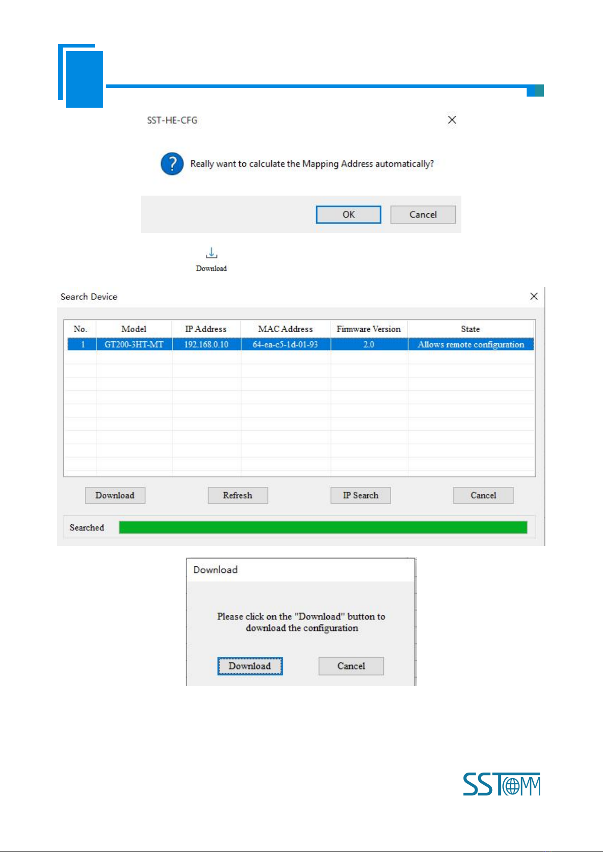
4. Select the gateway and click "Upload" in the following "device searching" dialog box;
5. You will see the factory default configuration settings are shown below:
Note: There are already two commands and an IP Address preset into the device. You can edit these parameters
for your needs.
Command ID1 is pre-configured to read the PV. (For your reference, the default configuration for this command is
shown below.)

User Manual
3-channel HART/Modbus TCP Gateway
GT 200-3HT-MT
www.SSTAutomation.com 8
Command ID3 is pre-configured to read the PV, SV, TV, and QV. (For your reference, the default configuration for
this command is shown below.)
2.1.3 Configuration
1. Open the SST-HE-CFG software installed on your computer.
2. Click Upload to upload the configuration.
3. Click “OK”. Select the gateway and Upload.

User Manual
3-channel HART/Modbus TCP Gateway
GT 200-3HT-MT
www.SSTAutomation.com 9
4. Select the “Fieldbus” on the left and configure the parameters as below:
5. Click the HART channel on the left and configure the parameters as below:
6. Click the AutoMap icon
User Manual
3-channel HART/Modbus TCP Gateway
GT 200-3HT-MT
www.SSTAutomation.com 10
7. Click the Download icon

User Manual
3-channel HART/Modbus TCP Gateway
GT 200-3HT-MT
www.SSTAutomation.com 11
2.2 Communication with Modbus TCP Client
The GT200-3HT-MT is able to connect HART instruments to Modbus TCP network as a Modbus TCP server. The
following example shows how the GT200-3HT-MT communicates with Modbus Poll (a Modbus simulator
software).
1. Configure the GT200-3HT-MT with some HART nodes and commands. In this example, the
GT200-3HT-MT is configured with HART commands 1, 3 and 6 for one node.
(1) Command 1: All the response data bytes can be read by the Modbus TCP client.
User Manual
3-channel HART/Modbus TCP Gateway
GT 200-3HT-MT
www.SSTAutomation.com 12
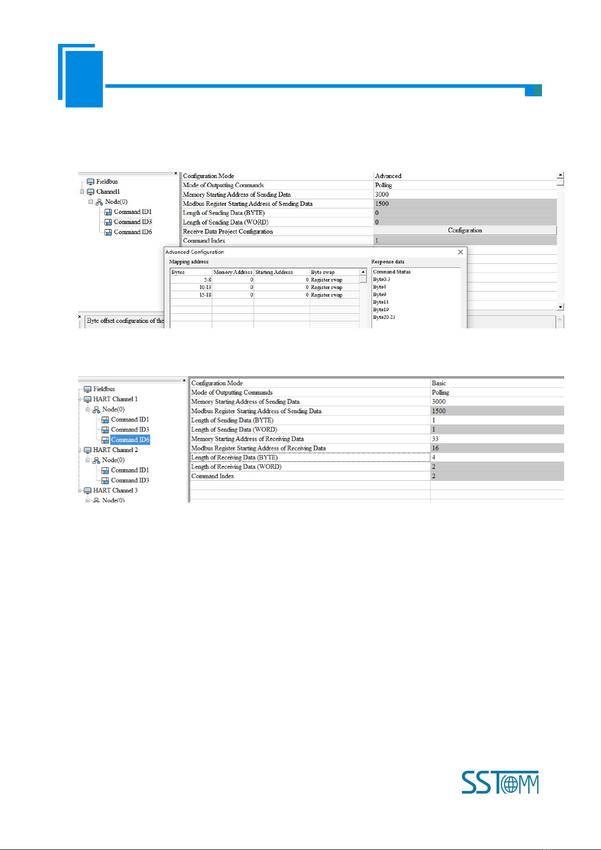
(2) Command 3: Advanced configuration mode. Double click any values to filter them out. Update the
configuration to read only bytes No.5-8, 10-13 and 15-18. The others can be filtered out. The remaining
bytes are the secondary, tertiary and quaternary variables.
(3) Command 6: 2-byte request and 2-byte response. The response data length includes the command status
bytes.

User Manual
3-channel HART/Modbus TCP Gateway
GT 200-3HT-MT
www.SSTAutomation.com 13
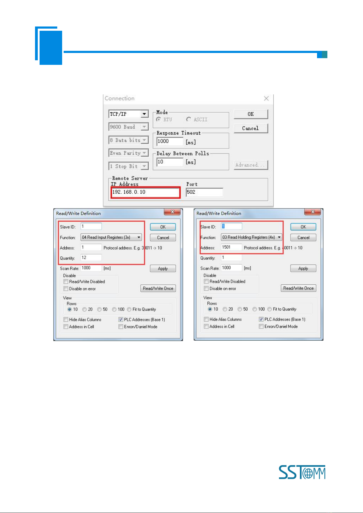
2. After mapping the data, check the buffer address in Conflict Detection window. The request data bytes of
command 6 are stored in 3000~3001 bytes. The response data bytes of command 1 are stored in 0~6 bytes,
command 3 in 7~18bytes and command 6 in 19~22 bytes.
According to the address table in chapter 6.1, Modbus TCP client should read/write the 4x1501 holding
register by function code 03 / 06 or 16, and read the 3x0001 to 3x0004 input registers by function code 04.
For Command 3 and 6, it’s 3x0005 to 3x0010 and 3x0011 to 3x0012.
User Manual
3-channel HART/Modbus TCP Gateway
GT 200-3HT-MT
www.SSTAutomation.com 14
This example uses Modbus Poll on the computer to simulate the Modbus TCP client. Set the correct server IP
and read/write parameters.

User Manual
3-channel HART/Modbus TCP Gateway
GT 200-3HT-MT
www.SSTAutomation.com 15
3. You can use the advanced function Memory Data Display (see chapter 5.2.7) or Diagnose (see chapter
5.2.8) to monitor the HART communication.
(1) Memory Data Display
(2) Diagnose: According to the specifications of HART command, you can convert the hexadecimal data to
float number.

User Manual
3-channel HART/Modbus TCP Gateway
GT 200-3HT-MT
www.SSTAutomation.com 16
2.3 Troubleshooting Multiple HART Devices
The GT200-3HT-MT can receive data from up to 15 HART devices connected on the same bus. The following
example shows how to configure the GT200-3HT-MT in multi-drop mode to receive data from multiple HART
nodes.
2.3.1 Identifying HART Slave Addresses
Each HART device can have an assigned slave address between 0-15. If the address of a HART device is
unknown, the SST-HE-CFG software can be used to identify the address with the following steps:
1. Select a single HART device to find the address for. Addresses will need to be found one at a time. Connect
the HART device to the GT200-3HT-MT using the wiring diagrams from Chapter 4.5.
2. Open the SST-HE-CFG software installed on your computer.
3. Click Upload to upload the configuration.
4. Select the gateway and click "Upload".

User Manual
3-channel HART/Modbus TCP Gateway
GT 200-3HT-MT
www.SSTAutomation.com 17
5. Select the "Fieldbus" on the left and configure the parameters as below:

User Manual
3-channel HART/Modbus TCP Gateway
GT 200-3HT-MT
www.SSTAutomation.com 18
6. Click the HART channel on the left, configure the parameters as below:
7. Right click the channel, select “Add Node”.
8. Right click on “Node(0)” and select “Add Command” and add Command ID3 box (double click on
“Command ID3” or select “Command ID3” and click “»”). Click OK.

User Manual
3-channel HART/Modbus TCP Gateway
GT 200-3HT-MT
www.SSTAutomation.com 19
9. Click “Command ID3” and configure the parameters as below:
10. Click the AutoMap icon
11. Click the Download icon

User Manual
3-channel HART/Modbus TCP Gateway
GT 200-3HT-MT
www.SSTAutomation.com 20
12. Check the LED indicators to verify the device status. If both TX and RX lights are flashing, then the device
is configured to slave address 0. If the RX light is not flashing, then change Network Mode to Multi-drop and
proceed to step 14.
13. Click the HART channel on the left and configure the parameters as below:
14. Right click the channel, select “Add Node”.
Table of contents
Popular Gateway manuals by other brands


Eaton
Eaton Moeller SmartWire-Darwin Series Hardware and engineering

Lucent Technologies
Lucent Technologies orinoco Getting started

ZyXEL Communications
ZyXEL Communications P-662H Series brochure

AudioCodes
AudioCodes Mediant 1000 Hardware installation manual

Grandstream Networks
Grandstream Networks GXW-4024 Technical specifications

HMS
HMS Intesis INMBSOCP 0100 Series Installation sheet