ST Fitness 8810 Use and care manual
A
ASSEMBLY
SSEMBLY
I
INSTRUCTIONS
NSTRUCTIONS
/ O
/ OWNERS
WNERS
M
MANUAL
ANUAL
Revision: CDate: 09/08
SERIAL NO. __________________________________________ PURCHASE DATE:_______________________
I
I
IMPORTANT
MPORTANT
MPORTANT:
:
:
READ ALL ASSEMBLY INSTRUCTIONS AND SAFETY PRECAUTIONS BEFORE USING THIS PRODUCT. REFERENCE ALL
SAFETY GUIDELINES AND WARNING LABELS. RETAIN PRODUCT LITERATURE FOR FUTURE REFERENCE.
S
SAFETY
AFETY
: PROPERLY WARM UP AND STRETCH BEFORE EXERCISING. IF YOU FEEL PAIN OR DIZZINESS AT ANY TIME WHILE
EXERCISING , STOP IMMEDIATELY AND CONSULT YOUR PHYSICIAN.
8810
8810
E
ELLIPTICAL
LLIPTICAL
T
TRAINER
RAINER
Part No. 06160

REFERENCE INFORMATION PAGE
Assembly Prep & Intro 2
PartsListing 3
HardwareChart 4
ProductExplodedView 5
Product Assembly Instruction 6-11
Computer Operation 12-18
Troubleshooting 19
Preventative Maintenance 20
WarrantyTerms 21
ProductRegistration 22
I
IMPORTANT
MPORTANT
P
PRECAUTIONS
RECAUTIONS
WARNING: To reduce the risk of injury, please read the following precautions before assembling or using this product.
1. It is the responsibility of the owner to ensure that all users of this equipment are adequately informed of stated precau-
tions.
2. Read all instructions and enclosed literature carefully. Understand the assembly and operation before using the equip-
ment.
3. Use equipment on a flat level surface. Use adjustment levelers on the bottom of equipment to help stabilize unit.
4. It’s recommended to place an exercise / product mat beneath the equipment for added protection of floors or carpets.
5. Keep children & pets away from equipment at all times. Unplug equipment for added safety while not in use.
6. Inspect product on a frequent basis. Tighten lose assemblies or hardware as needed. Replace worn or damaged parts.
7. This equipment is intended for internal home use only. Do not use in a non-residential environment.
Use in non- recommended environments can lead to serious injury and will void all related warranties & liabilities.
8. Recommended user weight should not exceed 350 lbs.
9. Frequently wipe equipment down with a dampened soft cloth.
10. Observe and adhere to all warning labels posted on equipment.
11. Properly warm-up and stretch before starting any strength training or cardio exercise routine.
12. If you feel pain or dizziness at any time while exercising, stop immediately and consult your physician.
Safety Warning: Before starting an exercise program, consult your physician. This is especially important for individuals over
the age of 35 or persons with pre-existing health problems. It’s important to read all instructions carefully. We assume no re-
sponsibility for personal injury or consequential damages sustained by or through the use of this equipment. Additional terms
& conditions are listed in the back of this manual or enclosed owners manual.
PAGE 1 TABLE OF CONTENTS
8810 E
8810 ELLIPTICAL
LLIPTICAL
T
TRAINER
RAINER

A
ASSEMBLY
SSEMBLY
P
PREPARATION
REPARATION
♦ The product assembly process has been documented in easy to follow stages. Please read all assembly
instructions carefully. Take time to reviewthe manual and familiarize yourself with the entire assembly
process before proceeding.
Assembly Tip: It is always helpful to pre-stage the items needed for each assembly step.
♦ To ensure ease of product assembly, please take time to verify the size and quantities of all required assem-
bly hardware. Use the itemized parts listing as reference.
♦ Perform product assembly in a 4ft. x 6ft. flat area. Note: After assembly is completed, allow a minimal of 2
-3ft. of space on each side of unit for user access and dismounting.
♦ The basic tools for assembling this product are included with main assembly hardware.
♦ Do not dispose of any packaging materials until assembly of the product is completed.
♦ If you experience problems with operation of the equipment after assembly, please review the troubleshoot-
ing reference page in this manual.
♦ Fill-out the product registration form and return it to us within 30-days of purchase.
♦ For added component life, follow the preventative maintenance tips listed in this manual.
♦ Please contact us if have additional questions or need service assistance.
PAGE 2ASSEMBLY PREP & INTRO.
C
CUSTOMER
USTOMER
S
SERVICE
ERVICE 1-877-530-7782

PARTS REFERENCE
PAGE 3
Item Part# Description QTY.
1 N/A MainBaseAssembly 1
2 ST23635 FrontStabilizerAssembly 1
3 ST23515 SideStabilizerAssembly 2
4 ST07347 Shroud/MastBoot 1
5 ST23649 Mast 1
6 12131 MainDataCable 1
7 ST10130 Computer 1
8 ST23637 RearStabilizerAssembly 1
9 ST31011 BottleTray 1
10 ST31012 TrayClamp 1
11 ST23517 LeftPedalArmAssembly 1
12 ST23519 RightPedalArmAssembly 1
13 ST23522 LeftSwingArmAssembly 1
14 ST23524 RightSwingArmAssembly 1
15 27112 Leveler 6
16 ST02153 CapScrewM8x1.25x25L 4
17 ST02131 CapScreww/LoctiteM8x1.25x15L 6
8810 P
8810 PARTS
ARTS
L
LISTING
ISTING
Item Part# Description QTY.
18 ST01897 CurvedWasher19x8.5x1.5t 8
19 ST02157 PhillipsScrewM6x1.0x35L 4
20 ST02140 TrussHeadScrewM5x.8x10L 12
21 ST02160 CapScrewM8x1.25x15L 8
22 14008 ACAdapter 1
23 ST02156 HexScrew M12x1.75x180L 2
24 ST02148 FlatWasher26x13x2.0t 4
25 ST02163 NylonNutM12x1.75x12t 2
26 ST01920 ShoulderBolt 2
27 ST02161 Flat Washer30x17x3.0 2
28 11109 PlasticWasher32x17x1.5t 2
29 01927 WaveWasher WW-16 2
30 ST02158 CapScreww/LoctiteM10x1.5x16L 2
31 ST05648 PivotCover 2
32 ST02152 FlatWasher16x8x2.0t 16
33 N/A
34 ST02159 Cap Screw
M8 x 1.25 x 20L 6
35 ST07413 ComputerBackCoverTop 1
36 ST07414 ComputerBackCoverBottom 1

8810 H
HARDWARE
ARDWARE
R
REFERENCE
EFERENCE
30
28
26
31
27 29
19
18
24 25
32
NOTE: Most of the listed assembly hardware has been packaged separately, but some hardware items have been preinstalled in the identified
assembly parts.In these instances, simply remove and reinstall the hardwareas assembly is required. Please reference theindividual assembly
steps and make note of all preinstalled hardware.
HARDWARE CHART PAGE 4
23
21
17 16
34

12
15
1
21
18
11
2
27
28
31
30
13
5
9
19
17
4
14
20
6
7
EXPLODED PARTS VIEW
PAGE 5
C
CUSTOMER
USTOMER
S
SERVICE
ERVICE 1-877-530-7782
8810 P
PARTS
ARTS
16
32
10
18
3
29
26
8
25
24
24
23
32
6
34
34
34
21
22
35
36
20

ASSEMBLY STAGE #1
Attach Stabilizers
Assembly Hardware Required:
#16 Cap Screw Qty. 4 #18 Curved Washers Qty. 2
#21 Cap Screw Qty. 4 #32 Flat Washer Qty. 16
#34 Cap Screw Qty. 6
Assembly Description:
A) Securely fasten the Front Stabilizer Assembly (#2) to the Base Assembly (#1) using 4-Cap Screws (#16) and 4-Flat
Washers (#32).
B) Attach the two Side Stabilizer Assemblies (#3) to the middle frame extrusion of the Base Assembly using 2- Cap Screws
(#21) and 2- Flat Washers (#32) from the front to back mounting location and 3- Cap Screws (#34) and 3- Flat Washers
(#32) from the top down and back to front locations (mounting instructions are per side) as shown above.
Assembly Notes: Use the Adjustable Levelers (#15) located on the bottom of the rear tracking frame and the Side Stabilizers to
level the equipment and prevent the base unit from rocking on an uneven surface.
♦ Assembly Stage #1 complete
ASSEMBLY INSTRUCTION PAGE 6
16
18
3
2 21
ADJUSTMENT LEVELER
1
15
32
8
32 34
34
21
3
21
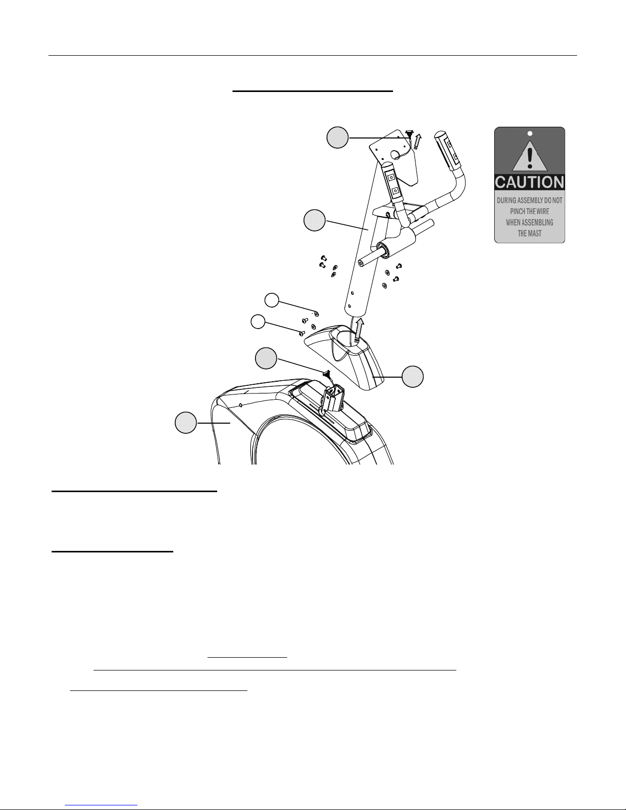
ASSEMBLY STAGE #2
Attach Mast
Assembly Hardware Required:
#17 Cap Screw w/ Loctite Qty. 6 #18 Curved Washer Qty. 6
Assembly Description:
A) Slide the Mast Boot (#4) over the lower end of the Mast (#5). For easier assembly, tape or hold the boot up out of the way of
the hardware mounting area.
B) Carefully route the Main Data Cable (#6) up through the Mast (#5). Gently pull the cable through while sliding the Mast
down onto the mounting area of the Main Base (#1). Note: Be careful not to pinch (damage) the cable during assembly.
C) Once the Mast (#5) is properly seated in the Base Frame, use the 2-Cap Screws(#17) and 2-Curved Washers(#18) to secure
the front mounting location. Note: Do not fully tighten the bolts until all hardware has been installed in the proper locations.
Also; Do not mount the “side” assembly hardware until the “front” mounting hardware is in place.
D) After the front assembly hardware is in place, carefully install 2-Cap Screws(#17) and 2-Curved Washers(#18) per side.
E) Leave the mounting hardware loose until the end of Assembly Step #5.
♦ Assembly Stage #2 completed
ASSEMBLY INSTRUCTIONPAGE 7
5
6
1
18
4
17
6
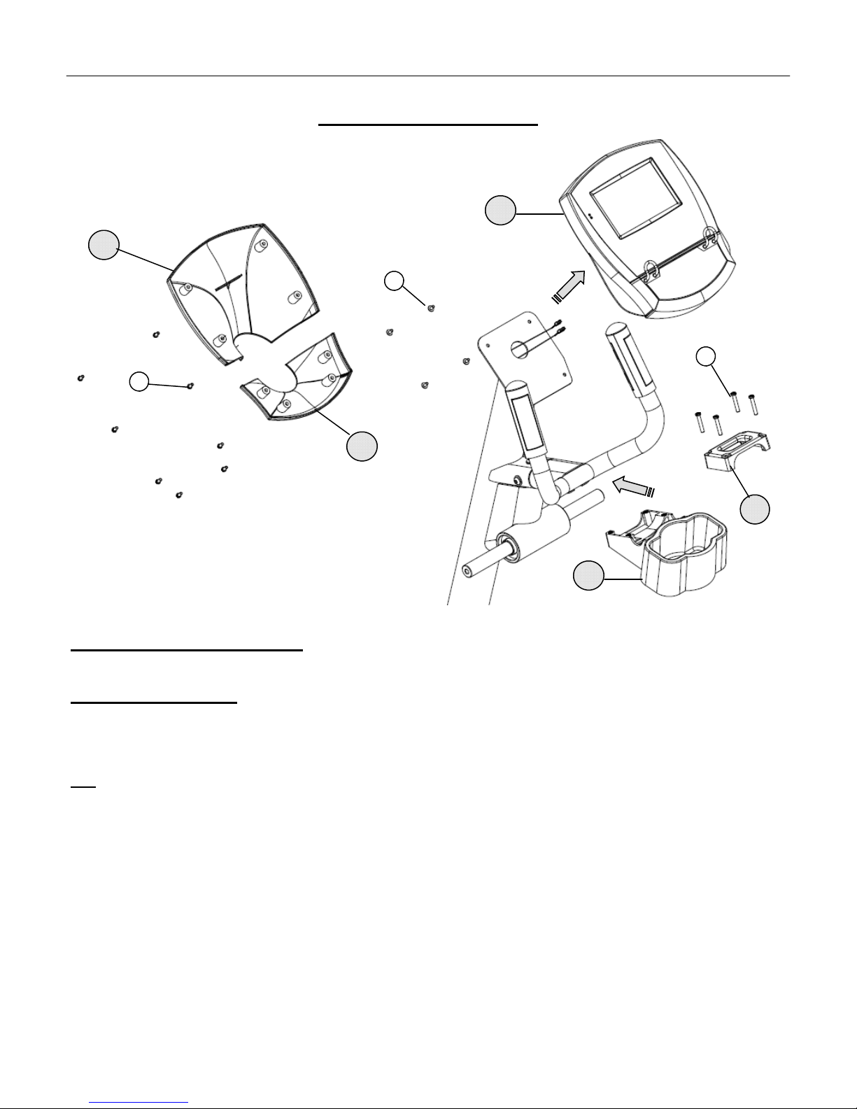
ASSEMBLY STAGE #3
Attach Computer
Assembly Hardware Required:
#20 Truss Head Screw Qty. 12 #19 Phillips Screw M6 x 35L Qty. 4
Assembly Description:
A) Remove the pre-installed hardware from the back of the Computer (#7). Install the supplied AA batteries in
the battery pack on the back of the Computer (#7).
B) Plug the connector ends of the Main Data Cable and 2-Heart Rate Cables into corresponding cable ends on the back of the
Computer Display (#7). Once the cables are connected, tuck the excess cable length down into the Mast. After tucking the
cable length away, align the Computer Display to the Mast mounting plate and secure it in place using 4-Truss Head
Screws (#20).
C) Install the computer back cover by first placing the Computer Back Cover Bottom (#36) in position and secure using 4-
Truss Screws (#20). Place the Computer Back Cover Top (#35) in position and secure using 4-Truss Screws (#20).
D) Align the Bottle Cage Lower (#9) and Bottle Cage Upper(#10) around the Mast and secure using 4 –Phillips Screws (#19).
♦ Assembly Stage #3 completed
ASSEMBLY INSTRUCTION PAGE 8
9
7
20
10
19
35
36
20

PAGE 9 ASSEMBLY INSTRUCTION
ASSEMBLY STAGE #4
Attach PedalArms
Assembly Hardware Required:
#23 Hex Screw Qty. 2 #24 Flat Washer Qty. 4
#25 Nylon Nut Qty. 2
Assembly Description:
A) Attach the Right Pedal Arm Assembly (#12) to the Right Roller Arm using 1-Hex Head Bolt (#23), 2-Flat Washers (#24),
and 1- Nylon Nut (#25) following the orientation shown above.
B) Attach the Left Pedal Arm Assembly (#13) to the Left Roller Arm using 1-Hex Head Bolt (#23), 2-Flat Washers (#24),
and 1- Nylon Nut (#25) following the same orientation used to mount the Right Pedal Arm.
♦ Assembly Stage #4 complete
24
23
12
11
25
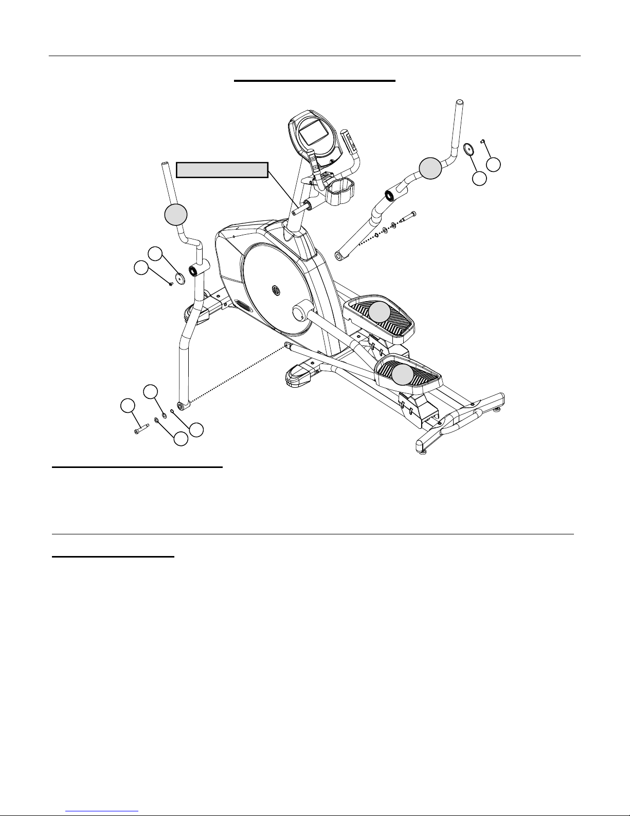
PAGE 10ASSEMBLY INSTRUCTION ASSEMBLY STAGE #5
Attach SwingArms
Assembly Hardware Required:
#26 Shoulder Bolt Qty. 2 #27 Flat Washer Qty. 2
#28 Plastic Washer Qty. 2 #29 Wave Washer Qty. 2
#30 Cap Screw w/ Loctite Qty. 2 #31 Pivot Cover Qty. 2
Safety Note: The Swing Arms will rotate freely on the Center Shaft until they have been attached to the corresponding Pedal Arm.
Assembly Description:
A) Slide the Left Swing Arm Assembly (#13) over the left end of the Center Pivot Shaft. Once the arm is in place, use 1-Cap
Screw w/ Loctite(#30) and 1-Pivot Cover(#31) to secure the arm on the shaft.
B) Slide the Right Swing Arm Assembly (#14) over the right end of the Center Pivot Shaft. Once the arm is on the shaft, secure
it in place using 1-Cap Screw w/ Loctite(#30) and 1-Pivot Cover(#31)
C) Connect the Left Swing Arm Assembly(#13) to the Left Pedal Arm Assembly(#11) using 1-Shoulder Bolt(#26), 1-Flat
Washer(#27), 1-Plastic Washer(#28) and 1-Wave Washer(#29).
D) Connect the Right Swing Arm Assembly(#14) to the Right Pedal Arm Assembly(#12) using 1-Shoulder Bolt(#26), 1-Flat
Washer(#27), 1-Plastic Washer(#28) and 1-Wave Washer(#29).
E) Go back and fully tighten the Mast mounting hardware that was installed in Assembly Step #2.
♦ Assembly Stage #5 completed
C
CUSTOMER
USTOMER
S
SERVICE
ERVICE 1-877-530-7782
14 31
13
26 28
29
27
30
CENTER PIVOT SHAFT
12
11
30 31
PAGE 11 ASSEMBLY INSTRUCTION
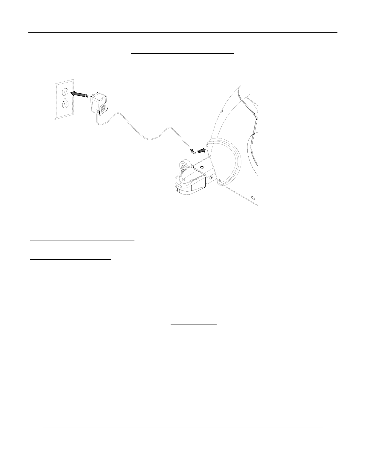
ASSEMBLY STAGE #6
Supplying Power
Assembly Hardware Needed: (NONE)
Assembly Description:
Note: This product requires AC voltage. Make sure bike is located near a wall outlet. (AC Adapter will have an
approximate cord length of 5 feet). Assembly Caution: The Adapter converts AC voltage to a low DC output. The
Adapter can be shorted if it is improperly grounded while plugging it into a wall outlet.
A) Plug in the cord end of the AC Adapter (#22) into the receptacle located on front of the Base Assembly-Shroud.
B) Plug the AC Adapter into an available wall outlet. SAFETY NOTE: For added safety around children, unplug the
AC Adapter from the wall when bike is not in use.
Helpful Reminders
♦ Before using the this product; please take the time to review the additional information regarding computer
operation, product maintenance, and related warranty information.
♦ Note the shroud orientation of AC Adapter receptacle. The receptacle (shroud) location will vary per product
model. Arrange placement of the unit so the AC adapter can easily reach the receptacle and an outlet plug.
C
CONGRATULATIONS
ONGRATULATIONS!
!
You have completed the assembly of this product and you are ready to start exercising toward a healthier lifestyle!

PAGE 12COMPUTER OPERATION
C
COMPUTER
OMPUTER
I
INSTRUCTION
NSTRUCTION
BUTTON INPUT & DISPLAY FUNCTIONS
NOTE: THESE ARE THE BASIC OPERATING FUNCTIONS OF EACH BUTTON. ACTUAL PROGRAMMING MAY REQUIRE A
ACTIVATION SEQUENCE OF MORE THAN ONE BUTTON (REFERENCE PROGRAM DESCRIPTIONS)
[A] QUICK START / PAUSE Activates & Stops Computer Functions. During a workout: 1) Pressing the button
once will pause the workout program. 2) Holding the button for 3 seconds will end the work
out program.
[B] ENTER Selects and sets display functions. This button will advance to the next display option.
[C] RESET Resets displayed values to zero. Holding the button down will activate a total display reset.
[D] LOWER DISPLAY This area will reference Time, Distance, Speed and all scrolling messages.
[E] DISPLAY GRID References the resistance level / profile.
[F] LEVEL References the resistance level value.
[G] WATTS References the user’s workload power output.
[H] RPM References the user’s pedal revolutions per minute.
[I] CALORIES References the user’s total accumulated calorie burn for the workout program and the
instantaneous calorie per hour burn rate.
[J] PULSE References the user’s heart rate (beats per minute).
[K] UP Increases displayed value settings. Increases resistance level during a workout program.
[L] DOWN Increases displayed value settings. Increases resistance level during a workout program.
[M]HEART RATE Quick access to only heart rate control programs during program selection.
[N] HEART RATE LOCK Begins heart rate control program by setting the current heart rate as the target.
[O] PROFILES Quick access to only preset profile programs during program selection.
[P] READING RACK Holds reading materials onto the face of the computer.
SPECIAL FEATURE
ENGLISH—METRIC This computer can be changed from English to Metric units by holding the Program Profiles
and Heart Rate Control buttons together during a total reset.

PAGE 13 COMPUTER OPERATION
C
COMPUTER
OMPUTER
I
INSTRUCTION
NSTRUCTION
DISPLAY FUNCTIONS / READINGS
TIME Computer display will accumulate total training time in 00:00 (minutes : Seconds). Computer will count
up to, or down from, a maximum value of 99:00.
Preset target training time: after selecting a workout program, the user is prompted via scrolling mes
sage in the lower display to “enter workout time”. The UP / DOWN buttons adjust the setting. Set
tings will be entered in 1:00 minute increments and the computer will count down from the set time.
The default time setting is 20 minutes. Once the desired time is set, press the ENTER button to lock
in the setting. Note: After a set training time is completed, the computer will “beep” for 8 seconds and
computer will reset to the initial setting.
SPEED The computer will register and display training speed. Units are either MPH or KPH
RPM The computer will read and display the user’s pedal revolutions per minute.
DISTANCE The computer accumulates training distance from 0.00 to a maximum of 99.9 units. Note: Units are
either miles or kilometer.
CALORIE The computer accumulates total calorie consumption (burn) during a training period and also and also
calculates the current calorie burn rate in calories per hour.
NOTE: THE REPORTED CALORIE DATA IS ONLY A REFERENCE GUIDE FOR THE USER.
IT SHOULD NOT BE USED IN COMPARISON OF CALIBRATED MEDICAL EQUIPMENT.
PULSE The computer will display the user’s heart rate reading. A blinking heart symbol and value will be dis
played when a heart rate signal is detected. This unit is equipped with two methods of detecting heart
rate. One method requires the use of a telemetric chest strap. The other method is by using the contact
heart rate grip sensors which require that BOTH hands make consistent contact with the grip sensors for
at least 30 seconds. Readings may become inconsistent if both hands are not in constant contact with the
sensors.
Preset target heart rate (heart rate control programs only): Once the prompt to “ENTER TAR-
GET HEART RATE” appears, use the UP / DOWNbuttons to adjust the setting from 30-240 BPM.
Press the ENTER button to lock in the setting. The default target heart rate value is 65% (220– AGE)
in the Fat Burn HR program and 85% (220-AGE) in the Cardio HR program. In the Heart Rate Inter-
val program there are two heart rate target settings, one peak heart rate and one recovery heart rate. The
default target heart rate is 90% (220-AGE) for peak and 70% (220-AGE) for recovery.
NOTE: HEART RATE READINGS ARE ONLY A REFERENCE OF A USER’S PULSE RATE
DURING TRAINING. THESE READOUTS SHOULD NOT BE USED IN COMPARISON WITH
CALIBRATED MEDICAL EQUIPMENT. SOME USERS MAY EXPERIENCE INCONSISTEN
CIES IN READINGS DUE TO THE NATURE OF THEIR PHYSICAL CONDITION.
WATT The computer will measure and display the user’s workload (power output) in Watts.
RESISTANCE The user can adjust the resistance level at any time during a workout program by pressing the UP &
DOWN buttons. A preset maximum resistance level may be set in all workout programs (except in
heart rate control programs). Once the prompt to “ENTER MAXIMUM RESISTANCE LEVEL” a
ppears, use the UP & DOWN buttons to adjust the setting from L1 to L20. Press the ENTER button
to lock in the setting.

COMPUTER OPERATION PAGE 14
C
COMPUTER
OMPUTER
I
INSTRUCTION
NSTRUCTION
1) ACTIVATION (START UP)
Start pedaling to activate the computer display. A beep will sound and the display will illuminate.
2) SET UP STEPS
2.1 Once activated, the display will show “U1” and the message “SELECT USER”. Use the UP OR
DOWN buttons to select either user ID 1 or user ID 2. Press the ENTER button to lock in the setting.
2.2 QUICK START FEATURE: Users may skip the ID set up and press the QICK START button to
begin training in the manual program. Only the resistance level will be adjustable in the quick start
mode, all other display values will default to zero.
QUICK START = FASTER SETUP PROCESS WITH LIMITED PROGRAMMING OPTIONS.
U1– U2 = ALLOWS USER TO SET UP CUSTOMIZED TRAINING PROFILE.
3) USING U1 - U2
3.1 TO BEGIN THE USER MAY CHOOSE U1 OR U2, The user has the option to press the RESET
button to modify the personalized user data (see 3.2) or to press the ENTER button to proceed to select
a training program (see 3.3).
3.2 ENTERING PERSONAL DATA:After pressing the RESET button the user will be prompted to set
GENDER, AGE, and WEIGHT. Press the ENTER button to lock in each setting.
3.3 SELECTING A TRAINING MODE (PROGRAM) : Once the user ID is chosen, the prompt
“SELECT WORKOUT PROGRAM” will appear followed by the program options (manual,
rolling hill, peak, plateau, mountain climb, hillinterval, strength interval, fat burn HR, cardio HR,
HR interval or custom profile). The user may press the UP OR DOWN buttons to select a training
program. Press the ENTER button to lock in the setting.
PRESETTING TARGET VALUES: Prompts for setting target values (time, resistance level, target
HR, etc.) will appear on the lower display. Prompts may vary depending on the chosen training pro
gram. The UP & DOWN buttons are used to adjust the target setting, the RESET button is used to zero
out a value. Press the ENTER button to lock in each setting.The user may skip adjusting the preset
target values by pressing the QUICK START button to begin the workout with the default setting.
4) OTHER DISPLAY FUNCTIONS
4.1 RESISTANCE This product is equipped with an adjustable resistance mechanism. This feature allows
the user to choose from varying resistance levels. At any time during a training program the resistance
may be changed by pressing the UP or DOWN buttons. NOTE: Heart Rate control programs
automatically adjust the resistance to control the user’s heart rate. In these programs the user may not
adjust the resistance.
4.2 WORKOUT SUMMARY: After completing a workout program the computer will dis
play a workout summary with the average speed and total distance travelled.
NOTE: Programs are completed when the preset time target reaches zero. For programs that do not
have a time count down the program may be stopped by holding the START/PAUSE button for 3
seconds.
PAGE 15 COMPUTER OPERATION
T
TRAINING
RAINING
P
PROGRAMS
ROGRAMS
♦ MANUAL PROGRAM
This is the basic training program and is the default program when the user selects the QUICK START feature.
If the MANUAL program is chosen after user ID selection, the user is able set Target Functions (Workout Time
& Maximum Resistance Level)
Resistance Adjustment: The display will reference 1-20 levels of training resistance. Level 20 will be highest
resistance setting. Use the UP & DOWN buttons to select a desired resistance setting. The display graph will
change as resistance levels are changed. Each row (segment) equals one level of resistance. The resistance level
value is displayed in the lower left corner of the screen. Note: Resistance levels can be adjusted anytime during
the training program.
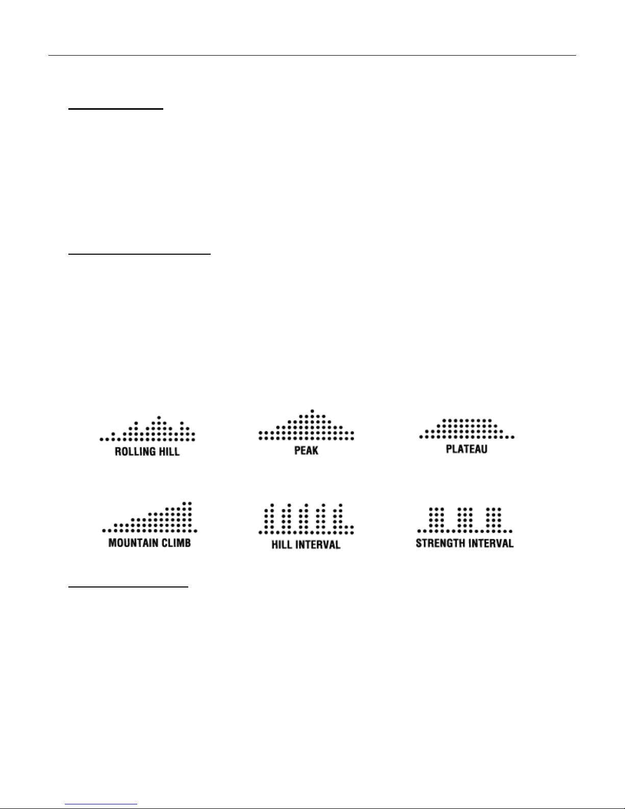
♦ PRESET PROFILE PROGRAMS -
ROLLING HILL, PEAK, PLATEAU, MOUNTAIN CLIMB, HILL INTERVAL, AND STRENGTH
INTERVAL
These training modes are based on preprogrammed course (resistance) profiles. The display grid will reference a
individual profile for each of the modes listed above. The resistance will automatically adjust to meet the grid
profile during a training session. These program are ideal for individuals who want to vary their training. Users
also have the option to set additional Target Functions (Workout Time & Maximum Resistance Level).
Resistance Adjustment: Though the resistance level is preset to match the training grid, the user is be able to
adjust the resistance level at any time by using the UP &DOWN buttons.
♦ CUSTOM (USER DEFINED)
This program mode allows a user to set up a customized user training profile (resistance grid). A individual
training grid can be set up for each user (U1 -U2). Note: The computer will default to the last customized training
profile until a user decides to set a new course profile.
Set up (Resistance Profile): In order to set a customized profile, the user must press the RESET button when
prompted to “ENTER WORKOUT TIME”. Upon proper activation the beginning grid segment will be
flashing. Each segment can be adjusted using the UP & DOWN buttons. The resistance can be set up to level
20. Once a segment is set, press the ENTER button to lock in the desired setting. After the first segment is set,
the next segment will be flashing. Repeat the set up steps for each segment until a desired profile is developed.
Once the complete profile is set the user must press and hold the ENTER button for 3 seconds. After a profile is
accepted, continue setting a Workout Time Target or simply press the START button to begin training. Note: If
no Workout Time is set the computer will default to 20 minutes.

PAGE 16
Computer Operation
T
TRAINING
RAINING
P
PROGRAMS
ROGRAMS
♦ TARGET HEART RATE MODES– FAT BURN , CARDIO AND HR INTERVAL TRAINING PROGRAMS
This training is base on Zone Training. This type training requires an individual to exercise within a set percent
age of their maximum heart rate. A users maximum heart rate is based on a basic formula; (220 BPM - Users
Age = Maximum HR). In order to accurately train in these modes the user should make sure to have entered
their Gender, Age, and Weight during USER ID set up. After selecting one of the Heart Rate Training Modes,
use the UP / DOWN button to enter a desired HR training value. Press the ENTER button to lock in the desired
zone setting. The defaults settings; 65% in the FAT BURN MODE, 85% in the CARDIO MODE, 90% in the
PEAK INTERVAL MODE, and 70% in the RECOVERY INTERVAL MODE. Users will also have the
option to set additional Target Functions (Workout Time).
Resistance Adjustment: The resistance will auto-adjust according to heart rate presets. If a user’s heart rates falls
under the preset targets, the resistance auto-adjust up one level approximately every 30-seconds until target rate is
achieved. If a users heart rate exceeds the target presets, the computer will auto-adjust down the resistance one
level until target is reached. For training safety, the computer will stop functioning and beep, if a user continues to
exceed a target heart rate for more than 30-seconds at the lowest resistance training level.. NOTE: At any time
during a Heart Rate Control Program you can use the UP & DOWN buttons to adjust the target HR value if you
find the current value is either too difficult to maintain or too easy.
HEART RATE LOCK key: The Heart Rate Lock key is a quick and easy way to begin a Heart Rate Training
Mode program. Once you are familiar with using the Heart Rate Training Modes and have determined your
preferred target HR value you can begin a Heart Rate Training Mode with two key strokes. Simply begin your
workout by pressing the QUICK START key and begin to warm up. Once your heart rate reaches your pre-
ferred target HR value, press the HEART RATE LOCK key to automatically switch to the Heart Rate Training
Mode. Workout Time will start at zero and count up.

PAGE 17 TRAINING CHART
T
TRAINING
RAINING
L
LOG
OG
DATE USER PRO-
GRAM
RESISTANCE
LEVEL TOTAL TIME TOTAL
DISTANCE
TOTAL CALO-
RIE HEART RATE

PAGE 18
TRAINING CHART
T
TRAINING
RAINING
L
LOG
OG
DATE USER PRO-
GRAM
RESISTANCE
LEVEL TOTAL TIME TOTAL
DISTANCE
TOTAL CALO-
RIE HEART RATE

PAGE 19 TROUBLESHOOTING
T
TROUBLESHOOTING
ROUBLESHOOTING
T
TIPS
IPS
PROBLEM DESCRIPTION SUGGESTED SOLUTION
1. NO DISPLAY 1.1 CHECK AC ADAPTER FOR PROPER VOLTAGE OUTPUT (9-12 VDC).
1.2 INSPECT PLUG-IN RECEPTACLE ON THE FRONT OF THE UNIT FOR
DAMAGE.
1.3 CHECK CABLE CONNECTIONS: MAKE SURE CONNECTIONS ARE SECURE
AND IN THE CORRECT ORIENTATION.
1.4 CHECK CABLE ASSEMBLIES FOR DAMAGE: PINCH POINTS & POSSIBLE
SHORTING OF WIRES.
1.5 CHECK FOR POSSIBLE COMPUTER DAMAGE: CRACKED DISPLAY
WINDOW (BLACK SCREEN).
* If computer still fails to operate after checking these suggestions, contact us for techni-
cal support.
2. PRODUCT WILL NOTSIT LEVEL 2.1 USE LEVELERS ON THE BOTTOM OF THE REAR STABILIZER AND THE
MIDDLE OF THE MAIN FRAME TO ADJUST EQUIPMENT STABILITY.
3. PEDAL WOBBLE 3.1 CHECK TO MAKE SURE PEDAL ARM MOUNTING HARDWARE IS IN-
STALLED CORRECTLY (ORIENTATION) AND TIGHT.
4. NO SPEED / RPM READING 4.1 CHECK COMPUTER CONNECTION: MAKE SURE ALL THE CONNECTORS
ARE SECURE AND IN THE CORRECT ORIENTATION.
5. ERRATIC HEART RATE 5.1 MAKE SURE PALMS OF HAND ARE CENTERED ON GRIP SENSORS.
5.2 CHECK CABLE CONNECTIONS FROM HANDLE BAR ASSEMBLY TO THE
COMPUTER.
NOTE: A USER'S PHYSICAL CONDITION CAN EFFECT THE ACCURACY OF
A READING, AS WELL AS, UNCONTROLLABLE INTERFERENCES.
Make sure to reference the assembly steps & parts informationin this manual when performing any troubleshooting.
If you experience other technical problems or have additional questions, please contact us at:
C
CUSTOMER
USTOMER
S
SERVICE
ERVICE
1
1-
-877
877-
-530
530-
-7782
7782
This manual suits for next models
1
Table of contents


