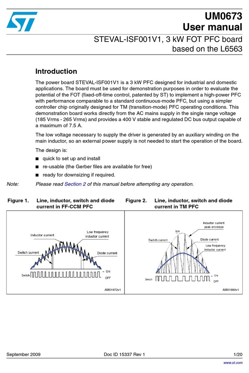
ST STEVAL-IFS013V2 User manual

August 2009 Doc ID15114 Rev 2 1/18
UM0602
User manual
ZigBee® USB dongle demonstration kit (STEVAL-IFS013V2)
1 Introduction
This document describes the hardware and software of the STMicroelectronics™ ZigBee®
USB dongle demonstration kit working under the Microsoft®Windows®98/2000/XP
operating systems.
The purpose of this design is to demonstrate the key features of STMicroelectronics ZigBee
PRO compliant wireless networking solutions. ZigBee PRO, the leading wireless control and
sensory network solution, stands apart from other RF solutions as the only standards-based
technology that:
■Addresses the unique needs of remote monitoring and control, and sensory network
applications
■Enables broad-based deployment of wireless mesh networks with low-cost, low-power
solutions
■Provides the ability to run for years on inexpensive primary batteries for a typical
monitoring application.
This particular demonstration kit primarly offers USB interface operating either under USB
communication device class (CDC) for virtual COM port connectivity or under device
firmware upgrade (DFU) class for reprogramming an application through USB. All design
source data are coming together with the kit and are ready to be reused in next
development. Target applications are: ZigBee network analysis and control through your PC,
universal PC based ZigBee “sink” node, low cost PC based node for rapid start of ZigBee
technology evaluation.
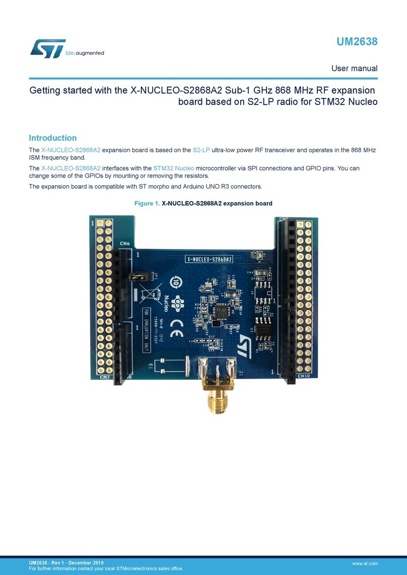
www.st.com

Contents UM0602
2/18 Doc ID 15114 Rev 2
Contents
1 Introduction . . . . . . . . . . . . . . . . . . . . . . . . . . . . . . . . . . . . . . . . . . . . . . . . 1
2 Description . . . . . . . . . . . . . . . . . . . . . . . . . . . . . . . . . . . . . . . . . . . . . . . . . 5
3 Getting started . . . . . . . . . . . . . . . . . . . . . . . . . . . . . . . . . . . . . . . . . . . . . . 6
3.1 System requirements . . . . . . . . . . . . . . . . . . . . . . . . . . . . . . . . . . . . . . . . . 6
3.2 Package contents . . . . . . . . . . . . . . . . . . . . . . . . . . . . . . . . . . . . . . . . . . . . 6
3.2.1 Hardware content . . . . . . . . . . . . . . . . . . . . . . . . . . . . . . . . . . . . . . . . . . 6
3.2.2 Software content . . . . . . . . . . . . . . . . . . . . . . . . . . . . . . . . . . . . . . . . . . . 6
3.2.3 Documentation . . . . . . . . . . . . . . . . . . . . . . . . . . . . . . . . . . . . . . . . . . . . . 6
3.3 Software driver installation . . . . . . . . . . . . . . . . . . . . . . . . . . . . . . . . . . . . . 6
3.4 Hardware installation . . . . . . . . . . . . . . . . . . . . . . . . . . . . . . . . . . . . . . . . . 7
3.4.1 Power supply . . . . . . . . . . . . . . . . . . . . . . . . . . . . . . . . . . . . . . . . . . . . . . 8
3.4.2 STM32 JTAG interface . . . . . . . . . . . . . . . . . . . . . . . . . . . . . . . . . . . . . . . 8
3.4.3 SPZB260-PRO debug and programming interface (SIF) . . . . . . . . . . . . . 8
4 Software equipment of the evaluation kit . . . . . . . . . . . . . . . . . . . . . . . . 9
4.1 Design firmware update . . . . . . . . . . . . . . . . . . . . . . . . . . . . . . . . . . . . . . . 9
4.2 Virtual COM port . . . . . . . . . . . . . . . . . . . . . . . . . . . . . . . . . . . . . . . . . . . . 9
4.3 Sensor - sink ZigBee application . . . . . . . . . . . . . . . . . . . . . . . . . . . . . . . . 9
4.3.1 Sensor . . . . . . . . . . . . . . . . . . . . . . . . . . . . . . . . . . . . . . . . . . . . . . . . . . 10
4.3.2 Sink . . . . . . . . . . . . . . . . . . . . . . . . . . . . . . . . . . . . . . . . . . . . . . . . . . . . 10
4.3.3 Serial commands supported on sensor and sink . . . . . . . . . . . . . . . . . . 10
4.3.4 Notes and limitations . . . . . . . . . . . . . . . . . . . . . . . . . . . . . . . . . . . . . . . 11
5 Running the USB to ZigBee dongle evaluation kit . . . . . . . . . . . . . . . . 12
6 Updating demonstration application in the evaluation kit . . . . . . . . . 14
7 Appendix . . . . . . . . . . . . . . . . . . . . . . . . . . . . . . . . . . . . . . . . . . . . . . . . . 15
8 Revision history . . . . . . . . . . . . . . . . . . . . . . . . . . . . . . . . . . . . . . . . . . . 17

UM0602 List of tables
Doc ID 15114 Rev 2 3/18
List of tables
Table 1. Serial commands supported on sensor and sink . . . . . . . . . . . . . . . . . . . . . . . . . . . . . . . . 10
Table 2. Serial commands supported on sink only . . . . . . . . . . . . . . . . . . . . . . . . . . . . . . . . . . . . . . 10
Table 3. Document revision history . . . . . . . . . . . . . . . . . . . . . . . . . . . . . . . . . . . . . . . . . . . . . . . . . 17

List of figures UM0602
4/18 Doc ID 15114 Rev 2
List of figures
Figure 1. Device manager window. . . . . . . . . . . . . . . . . . . . . . . . . . . . . . . . . . . . . . . . . . . . . . . . . . . . 7
Figure 2. USB to ZigBee dongle based on STM32 and SPZB260-PRO . . . . . . . . . . . . . . . . . . . . . . . 7
Figure 3. Control of sensor - sink demonstration application through Windows HyperTerminal . . . . 12
Figure 4. Windows HyperTerminal serial port settings. . . . . . . . . . . . . . . . . . . . . . . . . . . . . . . . . . . . 13
Figure 5. Evaluation board schematics - microcontroller part . . . . . . . . . . . . . . . . . . . . . . . . . . . . . . 15
Figure 6. Evaluation board schematics - ZigBee and interface connectors part . . . . . . . . . . . . . . . . 16

UM0602 Description
Doc ID 15114 Rev 2 5/18
2 Description
The ZigBee USB dongle demonstration kit tool is designed to demonstrate several
STMicroelectronics products:
■SPZB260-PRO is a low power consumption ZigBee module optimized for embedded
applications. It enables OEMs to easily add wireless capability to electronic devices.
The module is based on SN260 ZigBee network processor which integrates 2.4 GHz,
IEEE 802.15.4-compliant transceiver as well as IEEE 802.15.4 PHY and MAC. 24 MHz
high stability Xtal is available aboard the module to perform the timing requirements as
per ZigBee specifications. A single supply voltage is requested to power the module.
An integrated 2.5 GHz specific Murata antenna is aboard. The voltage supply also
determines the I/O ports level allowing an easy interface with the host system. The
module is controlled by means of a standard serial interface (SPI) allowing the
connections to a variety of host microcontrollers.
■The medium density devices STM32F103xx performance line family incorporates the
high-performance ARM®Cortex™-M3 32-bit RISC core operating at a 72 MHz frequency,
high-speed embedded memories (Flash memory up to 128 Kbytes and SRAM up
to 20 Kbytes), and an extensive range of enhanced I/Os and peripherals connected to two
APB buses. All devices offer two 12-bit ADCs, three general purpose 16-bit timers plus
one PWM timer, as well as standard and advanced communication interfaces: up to two
I2Cs and SPIs, three USARTs, an USB and a CAN. The STM32F103xx performance line
family operates from 2.0 to 3.6 V power supply. It is available in both the –40 to +85 °C
temperature range and the –40 to +105 °C extended temperature range.
A comprehensive set of power-saving mode allows designing low-power applications.
The complete STM32F103xx performance line family includes devices in 5 different
package types: from 36 pins to 100 pins.

Getting started UM0602
6/18 Doc ID 15114 Rev 2
3 Getting started
3.1 System requirements
In order to use the USB to ZigBee dongle evaluation kit with the Windows operating system,
a recent version of Windows, such as Windows XP, Windows 98, Windows Millennium or
Windows 2000 must be installed on the PC.
The version of the Windows OS installed on your PC may be determined by clicking on the
“system” icon in the control panel.
3.2 Package contents
The low-speed USB to ZigBee dongle evaluation kit includes the following items:
3.2.1 Hardware content
●One evaluation board with USB connector and ZigBee module
●One soldered STM32F103CBT6 ARM-based 32-bit microcontroller device (TQFP48
package). This is a Flash device allowing up to 10 thousands reprogramming cycles.
The STM32F103CBT6 is delivered already programmed with the evaluation firmware.
3.2.2 Software content
●STM32™ design firmware update (DFU) firmware
●STM32 DFU application for ZigBee sink node that collects data from a sensor network
●STM32 DFU application for ZigBee sensor node that simulates sensing node
3.2.3 Documentation
●STM32F103xx and SPZB260-PRO datasheets
●PCB production data
●STM32F103 and ZigBee flyers
●This user manual UM0602.
Note: Software content and documentation are on enclosed CD.
3.3 Software driver installation
To install the software driver of the virtual COM port, follow the following steps:
●Connect the ZigBee USB dongle to your PC/laptop USB port and let the Windows
recognize the CDC class device
●Indicate to the PC the location of the stmcdc.inf file (already provided in the kit)
At the end of the installation a new COM port appears in the device manager window as
shown in Figure 1.

UM0602 Getting started
Doc ID 15114 Rev 2 7/18
Figure 1. Device manager window
3.4 Hardware installation
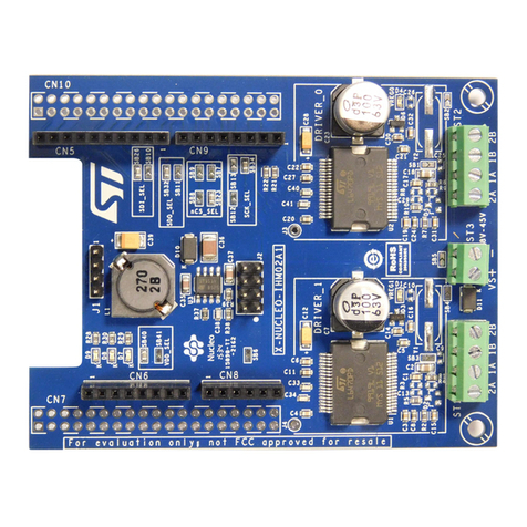
Figure 2 shows the location of the main components of the evaluation board. The schematic
drawing is given in Figure 5 and Figure 6.
Figure 2. USB to ZigBee dongle based on STM32 and SPZB260-PRO

Getting started UM0602
8/18 Doc ID 15114 Rev 2
3.4.1 Power supply
The USB to ZigBee dongle evaluation board is directly supplied by the USB connector (bus-
powered) and therefore does not require an external voltage supply.
3.4.2 STM32 JTAG interface
The 8-pin connector CN3 must be connected to a programming tool in order to program or
erase the microcontroller Flash memory.
For further information, please refer to both the Reference manual RM0008 - “Low-,
medium- and high-density STM32F101xx, STM32F102xx and STM32F103xx advanced
ARM-based 32-bit MCUs” and the Programming manual PM0042 - “STM32F10xxx Flash
programming”, available online from www.st.com/mcu.
Note: The USB cable must be plugged in to supply the board with voltage.
3.4.3 SPZB260-PRO debug and programming interface (SIF)
In order to program the integrated Flash and debug the software application within the
SPZB260-PRO, a synchronous serial interface, known as SIF, connects either Ember's™
InSight™ Adapter (ISA) or Ember's USB link programmer directly to the XAP2b core and
integrated memory bus. The SIF is a synchronous port which operates in a similar
command/response manner as JTAG. It uses four, dedicated pins (SIF_CLK, SIF_MISO,
SIF_MOSI and nSIF_LOAD) from the SPZB260-PRO. This interface is available through
optional connector CN1.

UM0602 Software equipment of the evaluation kit
Doc ID 15114 Rev 2 9/18
4 Software equipment of the evaluation kit
This part of the document presents key software techniques that are used and ready for
testing in the USB to ZigBee dongle evaluation kit.
4.1 Design firmware update
This paragraph describes the implementation of a device firmware upgrade (DFU) capability
in the STM32F103xx microcontroller. It follows the DFU class specification defined by the
USB Implementers Forum for reprogramming an application through USB. The DFU
principle is particularly well suited to USB applications that need to be reprogrammed in the
field: The same USB connector can be used for both the standard operating mode and the
reprogramming process.
This operation is made possible by the IAP capability featured by most of the
STMicroelectronics USB Flash microcontrollers, which allows a Flash MCU to be
reprogrammed by any communication channel.
The DFU process, like any other IAP process, is based on the execution of firmware located
in one small part of the Flash memory and that manages the erase and program operations
of the others Flash memory modules depending on the device capabilities: it could be the
main program/code Flash, data Flash/EEPROM or any other memory connected to the
microcontroller even a serial Flash (through SPI or I2C etc.). In case of the USB to ZigBee
dongle evaluation kit is DFU used to program the internal Flash memory.
Refer to the UM0412, DfuSe USB device firmware upgrade STMicroelectronics extension,
for more details on the driver installation and PC user interface.
4.2 Virtual COM port
In modern PCs, USB is the standard communication port for almost all peripherals. The
virtual COM port feature used in the standard firmware delivery provides a simple solution to
bypass need of dedicated PC software equipment or drivers for our evaluation board
control. It uses the USB as a COM port by affecting the legacy PC application designed for
COM port communication.
The target of virtual COM port feature in our evaluation design is to bridge ZigBee node
serial control port located on STM32 to USB and to provide communication between
a laptop (without RS-232 port) and our evaluation board. The PC application used in the
communication is Windows HyperTerminal.
4.3 Sensor - sink ZigBee application
An example of a complete application that implements a distributed sensor network with
1 or more data collection points (called “sensors”) and 1 or more data storage points (called
“sinks”) is partially included in your standard evaluation kit delivery. A sink node sends out
advertisements (SINK_ADVERTISE) at regular intervals using a multicast (after making
a many-to-one route request). When a sensor without a sink hears this multicast, it sends
a message (SENSOR_SELECT_SINK) requesting to use this sink (after setting its address
table entry to the sink). If the sink has a free address table entry it responds with a sink

Software equipment of the evaluation kit UM0602
10/18 Doc ID 15114 Rev 2
ready message (SINK_READY) and, at that point, the sensor is free to send data (DATA) to
the sink at fixed intervals (as set by SEND_DATA_RATE).
Note: The sink, sensor applications require the user interaction through the serial communication
channels (virtual COM through USB). Press the “?” key on the hyper terminal for printing the
user help menu. See the Section 4.3.3: Serial commands supported on sensor and sink for
a description of the available serial commands.
4.3.1 Sensor
A device that takes data readings from some input source and passes these readings to
a particular collection point. Many sensors report to a single sink. When the sensor
application joins the network, led LD2 on the board will blink (visual signal that the node is
active and joined to a network).
4.3.2 Sink
Sink is a device that serves as a collection point for 1 or more sensor devices. In this
example, the sink is set up to be the ZigBee coordinator device, and it forms the network
automatically on first startup and retains these settings across reboots. Once the sink
application starts running, led LD2 on your evaluation STEVAL-IFS013V2 board will blink
(visual signal that the node is active).
4.3.3 Serial commands supported on sensor and sink
Table 1. Serial commands supported on sensor and sink
Command Response / description
lTells the node to send a multicast hello packet
!Leave the ZigBee network so on node reset the sink can form a new network
iPrints info about this node including channel and power
?Prints the help menu
5Simulate button B1 press - turns permit join, allowing other nodes to join to this node
6Leave the ZigBee network
aPrints the address table
mPrints the multicast table
cPrint child table
kPrint the security keys
Table 2. Serial commands supported on sink only
Command Response / description
f Force the sink to advertise
* Switch the network key: send the key followed by a switch key command 30 s later
& Send a switch key command. This is needed only if the device sent a new key and then
reset before it was able to send the switch key command

UM0602 Software equipment of the evaluation kit
Doc ID 15114 Rev 2 11/18
4.3.4 Notes and limitations
●This application defaults to using a fixed set of network parameters, with a default
channel setting of 26.
(Remove the #define USE_HARDCODED_NETWORK_SETTINGS line in the
common.h header file to allow the application to dynamically select its network
parameters.)
●Although the example portrays a single sink node that acts as a ZigBee coordinator, the
application could be easily adapted to allow a variant of the sink node that joins the
network as an ordinary ZigBee router so that multiple sinks can be supported.
●This application uses a “push” style of communication, where the sensor sends reports
to the sink without needing to be asked for this data. This is more efficient than a “pull”
model, where a device only transmits data when asked to do so by another device,
because it cuts the amount of traffic in half, thereby reducing the number of collisions
and routing burden in the network.
●The data reports used in this example are fixed size packets (of a size defined by
SEND_DATA_SIZE). The data contents are simply a 16-bit actual temperature value,
measured at the sensor side.
●The application uses a constant called MISS_PACKET_TOLERANCE as a threshold
for fault tolerance. On the sensor, this controls how many message timeouts can be
permitted between the sensor and sink before the sensor decides to attach itself to
a different sink. For a sink, this controls how many data reports can be missed from
a sensor before the sink “forgets” about the sensor (stops maintaining a record of its
attachment). Although bindings are kept on the sink node to track the attached sensors,
these could easily be made temporary (used only for the SINK_READY message) to
allow the sink application to support more nodes without enlarging the binding table,
assuming that the sink application does not care which sensors and how many sensors
are attached to it.
●The sensor advertisement is a broadcast. The behavior of such a broadcast in the
network depends on the network topology and density. ZigBee limits the number of
broadcasts that can be active in a network to 10 to minimize the network disruption and
loss of bandwidth. As this network increases in size or density, the rate of the sensor
advertisement should be reduced in frequency.

Running the USB to ZigBee dongle evaluation kit UM0602
12/18 Doc ID 15114 Rev 2
5 Running the USB to ZigBee dongle evaluation kit
First, connect the evaluation board to the PC via the USB cable. As a result, the evaluation
board is enumerated as a STM™ virtual COM port device as shown in Figure 1, and is
ready to use.
To access the ZigBee serial control interface of pre-flashed “sink application” demonstration
you need to start Windows HyperTerminal (Figure 3) and setup port settings according to
the screenshot here below (Figure 4). UART communication speed 115200 kbps, 8 data bits
with no parity and 1 stop bit. Refer to Section 4.3: Sensor - sink ZigBee application for more
details about sink node behavior and control.
Figure 3. Control of sensor - sink demonstration application through Windows HyperTerminal

UM0602 Running the USB to ZigBee dongle evaluation kit
Doc ID 15114 Rev 2 13/18
Figure 4. Windows HyperTerminal serial port settings

Updating demonstration application in the evaluation kit UM0602
14/18 Doc ID 15114 Rev 2
6 Updating demonstration application in the evaluation
kit
For the STM32 the DFU mode is entered after an MCU reset if:
●The DFU mode is forced by the user: the user presses the key push-button during
a reset (while he is attaching the evaluation dongle to the USB).
●There is no correct code available in the applicative area: before jumping to the
applicative code, the DFU code tests if there is a correct top of stack address in the first
address in the applicative area of the internal Flash memory (for the STM32F103xx the
first applicative address is 0x0800 3000). This is done by reading the value of the first
applicative address and verifying if the MSB half-word is equal to 0x2000 (base
address of the RAM area in the STM32F103xx).
Once is the device in the DFU mode, you can simply update main application with support of
tools coming from STM in DfuSe package. For further information, please refer to user
manual UM0412 - Getting started with DfuSe USB device firmware upgrade
STMicroelectronics extension, available online from www.st.com/mcu.

UM0602 Appendix
Doc ID 15114 Rev 2 15/18
7 Appendix
Figure 5. Evaluation board schematics - microcontroller part
VDD_2 36
VSS_235
PA13 34
PA12 33
PA11 32
PA10 31
PA9 30
PA8 29
PB15 28
PB14 27
PB13 26
PB12 25
VBAT
1
PC13
2
PC14
3
PC15
4
PD0_OSC-IN
5
PD1_OSC-OUT
6
NRST
7
VSSA
8
VDDA
9
PA0-WKUP
10
PA1
11
PA2
12
VDD_3
48
VSS_3
47
PB9
46
PB8
45
PB7
43
PB6
42
PB5
41
PB4
40
PB3
39
PA15
38
PA14
37
BOOT0
44
PA3
13
PA4
14
PA5
15
PA6
16
PB0
18
PB1
19
PB2
20
PB10
21
PB11
22
PA7
17
VSS_1
23
VDD_1
24
STM32
U3
STM32F103CBT6
USBDP
USBDN
USBDN
USBDP
JTMS
JTCK
JTDI
JTDO
JTRST
NRST
C11
100 nF
2
1
B1
DFU / ZB
C7
100 nF
USB5V
R7 1 MΩ
C6 4.7 nF
C9
100 nF
UART_RX
UART_TX
SPI_MOSI
SPI_MISO
SPI_CLK
SPI_SEL0
HOST_INT
RSTB
WAKE_UP
BUTTON
USB_ACTIVITY
BUTTON
VBUS 1
D– 2
D+ 3
GND 4
SH1 5
SH2 6
USB_A
CN2
USB_1X90A
C10
20 pF (10 pf for EPSON)
C8
20 pF (10 pf for EPSON)
X1
EPSONFA-365,12 MHz SMD 30 pF
R11
1 MΩ
C12
100 nF
R4 4.7 Ω
R5
R3 1.5 kΩ
R10
10 kΩ
C13 C14
100 nF100 nF
R6
10 kΩ
R9 0 Ω
R8 0 Ω
BOOT1
BOOT0
DP_CON
DM_CON
DP_CON
DM_CON
AM00340a
3.3 V
3.3 V
3.3 V
3.3 V
3.3 V
3.3 V
3.3 V
3.3 V
4.7 Ω
(optional)

Appendix UM0602
16/18 Doc ID 15114 Rev 2
Figure 6. Evaluation board schematics - ZigBee and interface connectors part
C1
4.7 µF
3.3 V
USB5V
C2
1 µF
C3
1 µF
VIN
1
GND
2
INHB
3
VOUT
5
BYPASS 4
U2
LD3985XX33 C4
10 nF
AM00354a
SPI_MISO
SPI_CLK
RS TB
SPI_SEL0
PS_DATA
PS_FRAME
R2
10 KΩ
SIF_LOADB
SIF_MOSI
SIF_MISO
SIF_CLK
SPI_MOSI
LED_ACTIVE
SDBG
HOST_INT
WAKE_UP
RSTB
1
HOST_INT
2
SPI_SEL
3
SPI_MOSI
4
SPI_MISO
5
SPI_CL K
6
GND
7
VDD
8
SIF_CLK 9
SIF_MISO 10
SIF_MOSI 11
SIF_LOADB 12
PTI_EN 13
PTI_DATA 14
WAKE 15
ACTIVITY 16
SDBG 17
U1
SPZB260-PRO
R1
10 KΩ
C5
220 nF
3.3 V
3.3 V
3.3 V
3.3 V
JTRST
JTDI
JTMS
JTCK
JTDO
NRST
1
2
3
4
5
6
7
8
9
10
CN1
PS_FRAME
PS_DATA
RSTB
SIF_LOADB
SIF_MOSI
SIF_CLK
SIF_MISO
UART_RX
UART_TX
Internal pull-up
Internal pull-up
Internal pull-up
Internal pull-down
SDBG
1
2
3
4
5
6
7
8
CN3
JTAG (optional)
1
2
3
4
5
CN4
BOOT0
UART_RX
UART_TX
1
2
3
4
5
CN5
BOOT0
ZigBee debug I/F (optional)
PROG I/F (optional)
PROG I/F2 (pogo pads)
3.3 V
3.3 V
3.3 V
3.3 V
1 2
2.3 VLD1
LED_ACTIVE12
LD2 R13
220 Ω
R12
470 Ω
USB_ACTIVITY
USB activity green Link active red
3.3 V

UM0602 Revision history
Doc ID 15114 Rev 2 17/18
8 Revision history
Table 3. Document revision history
Date Revision Changes
13-Nov-2008 1 Initial release.
26-Aug-2009 2
Document reformatted, replaced devices: STEVAL-IFS013V1 by
STEVAL-IFS013V2, STM32F103C6T6 by STM32F103CBT6 and
SPZB260 by SPZB260-PRO, SN260 debug interface by SPZB260-
PRO debug interface, removed STEVAL-IFS009V1, updated
Section 3.2.2, Section 4.3.1, Section 4.3.3, Figure 2, Figure 5,
Figure 6 and Tab le 1 , added Table 2 .

UM0602
18/18 Doc ID 15114 Rev 2
Please Read Carefully:
Information in this document is provided solely in connection with ST products. STMicroelectronics NV and its subsidiaries (“ST”) reserve the
right to make changes, corrections, modifications or improvements, to this document, and the products and services described herein at an
y
time, without notice.
All ST products are sold pursuant to ST’s terms and conditions of sale.
Purchasers are solely responsible for the choice, selection and use of the ST products and services described herein, and ST assumes no
liability whatsoever relating to the choice, selection or use of the ST products and services described herein.
No license, express or implied, by estoppel or otherwise, to any intellectual property rights is granted under this document. If any part of this
document refers to any third party products or services it shall not be deemed a license grant by ST for the use of such third party products
or services, or any intellectual property contained therein or considered as a warranty covering the use in any manner whatsoever of such
third party products or services or any intellectual property contained therein.
UNLESS OTHERWISE SET FORTH IN ST’S TERMS AND CONDITIONS OF SALE ST DISCLAIMS ANY EXPRESS OR IMPLIED
WARRANTY WITH RESPECT TO THE USE AND/OR SALE OF ST PRODUCTS INCLUDING WITHOUT LIMITATION IMPLIED
WARRANTIES OF MERCHANTABILITY, FITNESS FOR A PARTICULAR PURPOSE (AND THEIR EQUIVALENTS UNDER THE LAWS
OF ANY JURISDICTION), OR INFRINGEMENT OF ANY PATENT, COPYRIGHT OR OTHER INTELLECTUAL PROPERTY RIGHT.
UNLESS EXPRESSLY APPROVED IN WRITING BY AN AUTHORIZED ST REPRESENTATIVE, ST PRODUCTS ARE NOT
RECOMMENDED, AUTHORIZED OR WARRANTED FOR USE IN MILITARY, AIR CRAFT, SPACE, LIFE SAVING, OR LIFE SUSTAINING
APPLICATIONS, NOR IN PRODUCTS OR SYSTEMS WHERE FAILURE OR MALFUNCTION MAY RESULT IN PERSONAL INJURY,
DEATH, OR SEVERE PROPERTY OR ENVIRONMENTAL DAMAGE. ST PRODUCTS WHICH ARE NOT SPECIFIED AS "AUTOMOTIVE
GRADE" MAY ONLY BE USED IN AUTOMOTIVE APPLICATIONS AT USER’S OWN RISK.
Resale of ST products with provisions different from the statements and/or technical features set forth in this document shall immediately void
any warranty granted by ST for the ST product or service described herein and shall not create or extend in any manner whatsoever, any
liability of ST.
ST and the ST logo are trademarks or registered trademarks of ST in various countries.
Information in this document supersedes and replaces all information previously supplied.
The ST logo is a registered trademark of STMicroelectronics. All other names are the property of their respective owners.
© 2009 STMicroelectronics - All rights reserved
STMicroelectronics group of companies
Australia - Belgium - Brazil - Canada - China - Czech Republic - Finland - France - Germany - Hong Kong - India - Israel - Italy - Japan -
Malaysia - Malta - Morocco - Philippines - Singapore - Spain - Sweden - Switzerland - United Kingdom - United States of America
www.st.com

X-ON Electronics
Largest Supplier of Electrical and Electronic Components
Click to view similar products for Zigbee / 802.15.4 Development Tools category:
Click to view products by STMicroelectronics manufacturer:
Other Similar products are found below :
USB-KW41Z FRDM-KW41Z STEVAL-IFS013V2 STM32W108B-KEXT A2530R24A-LPZ ATRCB256RFR2-XPRO ATREB233-XPRO
ATZB-A-233-XPRO ATZB-X-233-USB ATZB-X-233-XPRO XB24-DKS XB24-DKS-INT XB24-DKSJ XBP09-DMDK XBP24-DKS
XKA2C-Z7T-W XKB2-A2T-WWC XKB2-AT-WWC XKB2-Z7T-WTZM XKB2-Z7T-WZM XKP9-DM-0 XKP9-DM-2 XKP9-DMB0
XK-Z11-M XK-Z11-M-W XK-Z11-M-WA XK-Z11-S XK-Z11-S-W XK-Z11-S-WA 410-201 410-201P-KIT ATREB231ED-EK ATZB-X-
233-USB MIKROE-1599 MIKROE-290 MIKROE-987 1323XNSK-SFTW EM35X-BBRD EM35X-DEV EM35X-DEV-IAR RD-0039-
0201 RD-0085-0401 STEVAL-IDZ301V1 STEVAL-IDZ302V1 STZB-SK/RAIS CC2430DB CC2538-CC2592EMK
Table of contents
Other ST Computer Hardware manuals

ST
ST X-NUCLEO-STMODA1 User manual

ST
ST TIP122FP User manual

ST
ST ST10R272L User manual

ST
ST X-NUCLEO-6283A1 User manual

ST
ST STM32 Nucleo User manual

ST
ST X-NUCLEO-53L1A1 User manual

ST
ST CLT01-38SQ7 User manual

ST
ST X-NUCLEO-BNRG2A1 User manual

ST
ST STEVAL-STWINMA2 User manual

ST
ST X-NUCLEO-AMICAM1 User manual