ST DELTA 1000/400A AC DC User manual

DELTA 1000/400A AC DC


1

Contents Page
1. Introduction A p plication and Features ..........................................................................3
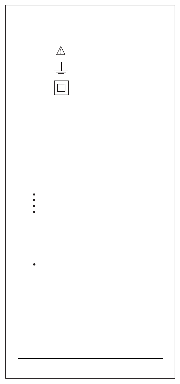
2. Safety features and safety precautions...........................................3
3. Switching the Power Clamp meter "ON".....................................................5
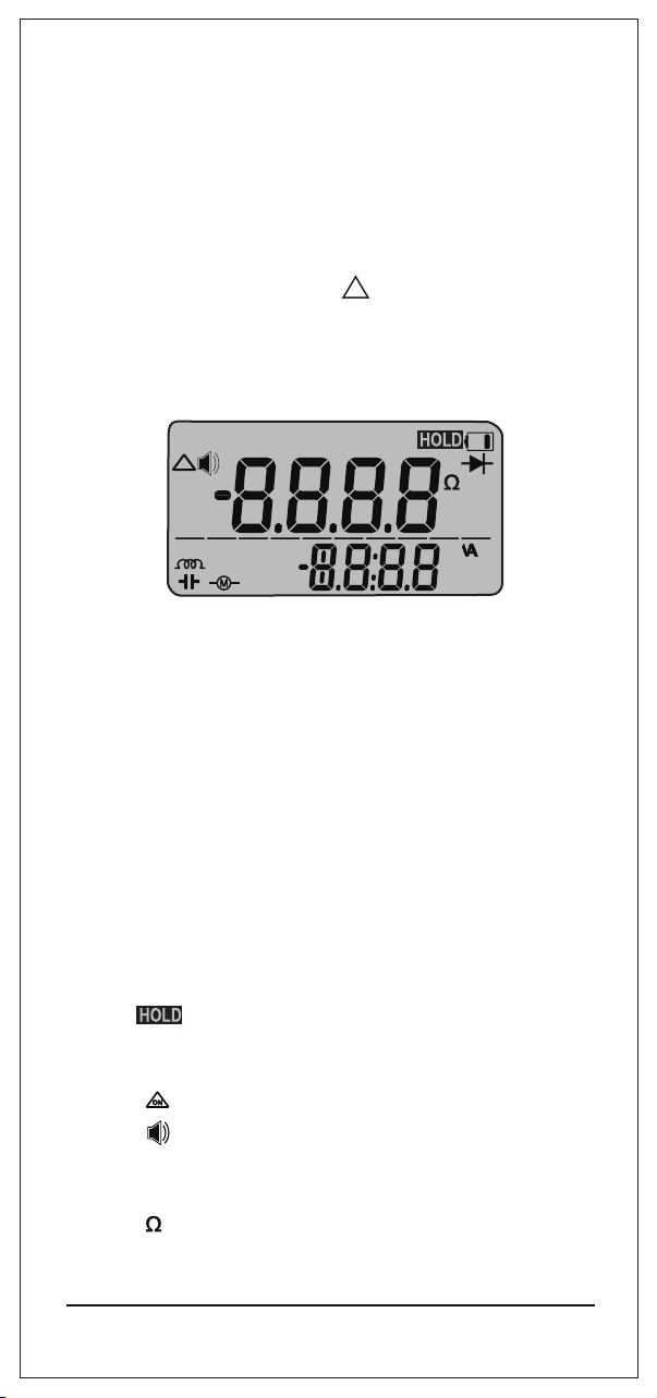
4 Liquid crystal display and backlit.......................................................................6
5.
Advanced Data “HOLD” Facilit y ......................................................7
6.
Minimum value and maximum value"MIN/MAX storage facility
. ...........8
7. Relative Function ............................................................................9
8. V oltage measurement ....................................................................10
9. Current measurement.....................................................................13
10. 1Ph Power measurement .............................................................19
11. 3-Phase 4 wire Power measurement ........... ................................23
13. NCV Detection.................................................................................31
................................31
14. Resistance, continuity & Diode measurement
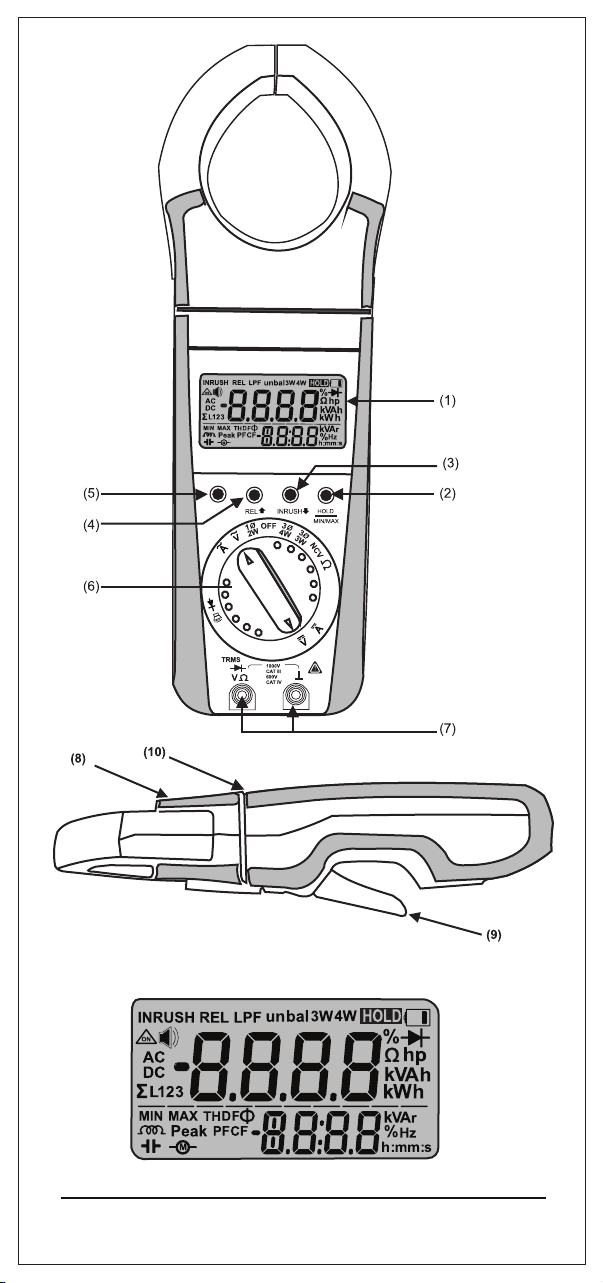
(1) Liquid crystal display
(2) Push button for data hold
(3) Push button for Down and Inrush
and MIN/MAX storage functions
(4) Push button for Up and Relative
Function
(5) Multifunction push button
(6) Function selector switch.
(7) T erminal sockets
................................33
16. Specifications...................................................
15. Empty Positions...............................................................................32
17.1 Battery .................................................................................37
17.2 Periodic Check-up ...................................................................37
(8) Rotary mechanism for clamp jaws.
(9) Safe trigger mechanism.
17. Maintainance ..................................................................................37
18. Servicing ..........................................................................................37
(10) Limit of safe access for hand held.
8.1 T HD .................... ....................................................................10
8.2 DF ......................
....................................................................10
8.3 CF ...........................................................................................11
8.4 Peak Min/ Peak Max
................................................................11
8.5 Frequency................................................................................11
8.6 Individual Harmonic measurement
8.7 LPF...........................................................................................11
9.1 T HD ................... .....................................................................14
9.2 DF ......................
9.3 CF ......................
9.4 Peak Min/ Peak Max
9.5 Frequen cy
9.6 Individual Harmonic measurement
9.7 LP F ..........................
9.8 Inrush Current measurement
9.9 A mpere hour measurement
....................................................................15
....................................................................15
...............................................................15
...............................................................................15
.........................................15
...............................................................15
.................................................17
.....................................................18
10.1 kVA,kW ,kVAr
10.2 PF & Ф..............
10.3 H P......................
10.4 DC Power
10.5 kWh measurement
........................................................................19
....................................................................19
....................................................................19
............................................................................19
...............................................................22
11.1 3 Ph 4W unbalance Load Power
11.2 3 Ph 4W balance Load Power
..........................................23
. . . . ..........................................25
12. 3 Phase 3 Wire Power measurement ........... ................................27
12.1 3 Ph 3W unbalance Load Power
12.2 3 Ph 3W balance Load Power
..........................................27
. ..............................................29
2
..........................................11

1. Introduction , Application and Features:
Power Clamp meter is a Portable Digital multi functional measuring instrument .
designed for Measuring selected power network p a r a m e t e r s , AC/DC V oltage,
AC/DC current, Resistance, Co n t in u i t y , Diode and Freque n c y Apart From
basic quantities meter enables the measurement of additional quantities
calculated from values of voltage and current.
Power clamp meter is innovatively designed for increasing safety and comfort of
use r Rotating clamp jaws facilitate the measurement at physically awkward
position, vertical bus bars, conductors placed at position diffcult to access.
Clamp jaws can be opened or closed with the triggered placed at bottom side
placed away from the j a w s . This allows the user to place his/her hand at safer
distance from live cond. u ctor
.
Location and design of trigger eliminates fatigues caused by single finger
operation. It allows spreading the force required to open the jaws over more
than one finger to ensure comfortable operation.
Power Clamp meter have following f e atures
2. Safety features and safety precautions
Please note the following safety precautions:
Power Clamp meter provides a very high degree. of safety
The digital power clamp meter
in compliance with the safety standard IEC 61010-1:2010.
In case of incorrect use or careless handing, the safety of both user and power
clamp meter is not assured.
For proper use and safe handling,it is absolutely necessary to read and
understand the operating instructions before using the c. lamp meter
400A/1000A manufactured and tested
The
clamp meter must be
operated only by persons who understand
the danger of shock hazards and are aware of the necessary safety
precautions.Shock hazards exist wherever voltages of more than
30V(TRMS) are present.
Do not work alone in shock hazardous environment while carrying
out measurement.
Operators must use individual protective equip ment if
hazardous live parts of installation could be access.ible
Keep hands/fingers behind the edge that separates ro tating
jaws with hand held part(1 0 ) . This is the limits of the ha nd
held part during measurement.
The maximum permissible voltage between any of the terminal
sockets (7) and ground is 1000V.
3

voltages can occur on devic
e
voltage.
s with
environmental conditions are not
T ake into account that unexpected
under test (e.g.defective instrument).For example, capacitors may
be charged to a dangerously high
in good condition, e.g.no crac kedV erify that the test leads are
insulation, no open circuits in the leads or connectors.
This clamp meter must not be used for measurements on circuit
corona discharge (high voltage).
on HF circuits. Dangerous
composite voltages may exist there.
Be particularly careful when measuring
Measurements under moist
permitted.
Do not overload the measuring ranges beyond their allowable
capacities. Limit values are given in specifications. Ref. Chapter 16.
Please verify the performance of clamp meter after repairing
of the mete r before using it for actual measurement.
Do not use the clamp meter if obvious wear in jaw opening
is visible.
Protection provided by the digital clamp meter may be
impaired if the clamp meter is not used in a manner
specified in this user manual.
Measurements at power sources for low-voltage installations,
consumers, distributor terminals, devices connected permanently
Measurements in electrical circuits which are not directly
connected to the mains: for example electrical systems in motor
Measurements in building installations, stationary power
eters, mains terminals, primary over voltage protection devices.
Meaning of categories and their significance as per IEC61010-1
vehicles and aircraft, batteries etc.
to the distributor.
CAT III:
CAT IV:
CAT I:
which are electrically
connected to the low-voltage mains:with plugs, e.g. at home, in the
Measurements in electrical circuits
office or laboratory etc.
II:CAT
m
4

Repair, replacement of parts:
When opening the mete r , live parts may be exposed . Therefore , the
meter must be disconnected from the measuring circuit prior to opening
its case for repair or replacement of parts. If repair cannot be avoided
unless the meter is opened and live, this work must only be per
formed
by a qualified person who understands the danger involved.
Faults and abnormal stress:
When it is realized that the safe operation is no longer possible, take the
meter out of service and secure it against accidental use.
Safe operation may not be possible,
when the meter shows obvious signs of damage,
when the meter no longer functions, correctly
after prolonged storage under adverse conditions,
due to severe stress during transportation.
3. Switching the Power Clamp meter "ON"
Battery
W e have already fitted your meter with a 9V flat cell battery according to
IEC 6F22 or IEC 6R61. It is ready for operation. Before you use the meter
Meaning of the symbols on the device
Warning of a danger point
(Attention, refer to the user
manual)
Earth (ground)terminal.
Double or reinforced insulation
Instrument for over voltage
category III OR IV
CAT III/IV
for the first time or after storage, refer to section “ 17.1 Maintenance battery”
Switching the meter "ON"
Note:
Electric discharges and high-frequency influence may cause incorrect
information to be displayed and block the measuring process
meter by switching it OFF and ON again otherwise, check the battery
connections.
Rotate the function selector switch or knob from “OFF" posi.tion to another
Switch-"ON" is acknowledged by a sound signal.
.Reset the
Disconnect the clamp meter from the measuring circuit before
you open it, and see section "17. Maintenance".
5

Automatic TURN-OFF
The meter turns off automatica,lly when neither a push button nor the
function selector switch is operated for about 10 minutes.
How to prevent automatic TURN-OFF
In order to prevent automatic "TURN OFF" select "CONTINUOUYSL
ON" mode. For this, press “Down and Inrush” push button and the “Min/Max
and Hold " pushbutton together. The function “ CONTINUOUSLY ON ”
is shown on the LCD by the symbol
Turning the clamp meter OFF
Rotate the function selector switch to “OFF” position
ON
4. LCD & Backlit
s:
ON
Ф
RELINRUSH
k
Peak
h
A
Hz
:m
k
D
TH F
CFPF
AC
DC
hp
V
W
h
r
V
k
%
%
4W
3W
unbal
321
ΣL
m
MAXMIN
LPF
h
LCD of Clamp meter is as shown above, The digital display shows measured
value with sign. Description of remaining
symbol is as fol.l o w .
INRUSH
AC Inrush Current Measurement
REL
Relative Measurement
LPF
Low Pass Filter
unbal
Un Balance
bal
Balance
3W
Three Wire
4W
Four Wire
Continuous ON
Continuity Mode
AC
Alternating current
DC
Direct current
Resistance Measurement
hp
Horse Power
4W
Hold function
A
V
W
V
A
Ar
V
Ah
Wh
V olts
Amperes
Active Power
Reactive Power
Apparent Power
Ampere Hour
W att Hour
6

Backl it
The instrument is provided with Back-lit for taking
measurements in poor lighting conditions/dark areas.
Switching the Backlit ON
by pressing "M U L TIFUNCTION (YELLOW)" an d " U P / REL" keys
simultaneously the Backlit can be switched ON.
Switching the Backlit OFF
simultaneously the Backlit can be switc. hed OFF
by pressing "M U L TIFUNCTION (YELLOW)" an d " U P / REL" keys
5. Advanced Data
“HOLD”
facility
The HOLD function allows to automatically hold the measured values.
The meter holds the measured value on the digital display with a sound
signal and displays “ HOLD ” on LCD di.s p l a y The probes or clamp
measuring point and the measured value
on the digital display can be read.
can now be removed from the
1
L
Phase 1 Readings
2
L
Phase 2 Readings
3
L
Phase 3 Readings
ΣL1 32
Three phases system parameters
MIN
Minimum Value
MAX
Maximum Value
Low Battery
Diode Measurement
Inductive
Capacitive
D
TH
T otal Harmonic Distortion
DF
Distortion Factor
CF
PF
Power Factor
Crest Factor
Phase A ngle
Ф
Peak
Hz
Hertz
k
Multiplied by 1000(Kilo)
Peak Value of Current or voltage
Why W e Call this a s ADV ANCED HOLD Funct ion ?
s::mh m
Hours:Minutes:Seconds
Motor application
armonics Up to 49.
7

6.
Minimum value and Maximum value "MIN / MAX"
storage faci l i t y .
With the MIN/MAX function, we can hold the minimum and the maximum
measured value which was applied to the input of the clamp meter after
activating MIN/MAX function.The most important application is the
determination of the minimum and the maximum value for long-term
monitoring of measured quantities.
The data “MIN MAX ” function is switc h e d O F F , when
The “HOLD / MIN MAX”
pushbutton is pressed for approx.2s.
(long press ) This is acknowledged by sound signals.
The function selector switch is operated
The Clamp meter is turned OFF and ON again.
To activate “MIN MAX ” function, press the “HOLD / MIN MAX” key twice.
Σ
ON
INRUSH
AC
DC
L
MIN
Peak
21
MAX
3
M
REL
TH
RIPPLE
D
PF
Ф
F
CF
LPF unbal3W4W
k
:
kV
W
h
V
k
%
%
A
Hz
m
hp
m s:
h
r
h
Now if we press hold key on any one of the parameter screen then not
only that parameter but all other measured parameter gets hold. including
all 49 harmonics.
So Advanced Hold feature benefits user to make data analysis of different
T o activate “HOLD ” function, momentarily press (short press)
the “HOLD / MIN MAX” key.
The data HOLD function is switch e d O F F , when
is
This is acknowledged by sound signals.
The “HOLD”
pushbutton pressed for approx. 2sec (long press).
The function selector switch is operated.
The Clamp meter is turned OFF and ON again.
parameters even after removal of input .
The “HOLD / MIN MAX” key will not be enabled in 3 phase power
measurement unless and until measurement of power is done.
The “HOLD / MIN MAX” key will be disabl e d i n N C V , kWh , Ahr functions.
Note : HOLD function not ap p l i c a b l e f o r 3 P 4 , 3P3W unbalanced system,
Diode and Continuity .
Figure 6.1 will show procedure for entering in hold and min max functions
“MIN MAX” is not applicable for Harmonics and the parameters on sub display
“MIN MAX” is also not applicable for 3P3W and 3P4W unbalanced load.
8

ON
DC A
ON
DC A
ON
DC
MIN
A
ON
DC
MAX
A
A
A
Short pressing of
Short pressing of
Short pressing of
Long pressing of
“HOLD / MIN MAX”. key
Short pressing of
“HOLD / MIN MAX”. key
Long press
Hold /Min /Max key
HOLD
Function
MIN/MAX
Function
MIN/MAX
Function
Fig 6.1: Screens for HOLD/MIN/MAX
9
7. Relative Function(REL)
With the R E L function, we can see the measured value with respect to
some value.
REL function is applicable for Voltage, Current and Resistance functions only.
The “RE L ” function is switched O F F , when
The “UP / REL”
pushbutton is pressed (short press)
This is acknowledged by sound signals.
The function selector switch is operated
The Clamp meter is turned OFF and ON again.
T
o activate “Relative” function, press the “UP/ REL” key .

8. V oltage measurement
According to the voltage to be measured, set the function selector
switch to V
Connect the test leads as shown in fig 8 . 1 . The socket
should be connected to the lowest potential ground available.
Select the appropriate working m o d e i . e . AC or DC o r ACDC by long
pressing Y ellow key (Function key).
For A C voltage mode following parameters measured.
8.1 THD (Total Harmonic Distortion)
th
Power Clamp meter can measure THD up to 49 Harmonic.
By default meter is prese n t o n THD measurement screen.
THD = n=2
49
2
th
( n order harmonic voltage RMS value)
2
( Fundamental wave voltage RMS value)
X 100 %
8.2 DF ( Distortion Factor)
th
Power Clamp Power can measure DF u p t o 4 9 Harmonic.
DF = n=2
49
2
th
( n order harmonic voltage RMS value)
2
( Voltage RMS value)
X 100 %
“
“
Fig 8 .1 V oltage measurement on electrical systems up to 1000V
FU C
NT
AU O
N
MA
A
DTA
NX
MI /MA
ON
OFF
L
MU IER
TME T
HHIN TUET
AB
SRMNS
FU C
NT
AU O
N
MA
A
DTA
NX
MI /MA
ON
OFF
L
MU IER
TME T
HIN TET
AB
SRMNS
FUNC AUTO
N
MA
DATA
MN
I/MAX
ON
OF
F
MULI
TME
INST MENTS
H
FUNC AUTO
N
MA
DATA
MN
I/MAX
ON
OF
F
MULI
TME
INST MENTS
H
1000V
CAT III
600V
CAT IV
INRUSH HOLD
MIN/MAX
REL
OFF
NCV
D
TH
AC
V
%
10

8.3 CF ( Crest Factor)
Power Clamp meter can meas. u r e C F CF is the ratio between the value
the peak voltage and corresponding RMS voltage.
CF = V (Peak Voltage Value)
m
V (RMS Voltage Value)
RMS
8.4 Peak Max / Peak Min
Peak Max /Min is the Positive / Negative peak value of measuring
waveform. It updates continuously as per measuring waveforms peak.
8.5 Frequency
Power Clamp meter measures frequency from 45 to 65 Hz.
8.6 Individual Harmonic measurement
th
Power Clamp meter can measure individual harmonic vol t a ge up to 49
Harmonic. Measured harmonic can also be seen in p e r c e n t ( % ) w .r.t.
fundamental voltage.
8.7 LPF measurement mode
Power Clamp meter have LPF mode for voltage measurement.
In LPF mode meter measures voltage bellow cut off frequency. The
cuto fff frequency of clamp meter for LPF mode i s 4 0 0 H z . This means
that meter will measure voltage having frequency bellow 400 Hz.
Note :
Note :
1) If display sho w s O L then it indicate s V oltage Overload
1) “----”” is displayed for THD, DF, CF, Freq and Harmonics if voltage level
2) “----” is disp l a y e d for THD, DF and Harmonics if signal frequency is
3) Meter will display 0 V if V <0.5V and in LPF mode meter will display
out of measuring band i.e. Freq Except 45Hz....65Hz
0 V if V < 1V
is below measurement band or applied v o l t a g e i s O L value i.e. 1020 V
i.e > 1020 V .
AC
V
LPF
Fig 8.2 Low Pass Filter mode
11
To enter in LPF mode Simultaneously press “yellow function key”
and “Hold/Min/Max” keys.

D
TH
AC
V
%
DF
AC
V
%
CF
AC
V
Peak
AC
V
V
MAXMIN
Peak
AC
V
V
MAX
Peak
AC
V
V
MAXMIN
Peak
AC
V
V
MIN
Hz
AC
V
AC
V
AC
%
AC
V
AC
%
ABAB
V
DC
TT
RH
IS
RH
IS
SS
Yellow key
Long Press
REL key
Short Press
REL
REL key
Short Press
REL
Yellow key Short Press
TT
RH
IS
RH
IS
SS
Yellow key Short Press
TT
RH
IS
RH
IS
SS
Yellow key Short Press
TT
RH
IS
RH
IS
SS
Yellow key Short Press
TT
RH
IS
RH
IS
SS
Yellow key Short Press
TT
RH
IS
RH
IS
SS
Yellow key Short Press
TT
RH
IS
RH
IS
SS
Yellow key Short Press
TT
RH
IS
RH
IS
SS
Yellow key Short Press
TT
RH
IS
RH
IS
SS
DC VoltageAC Voltage / THD
Distortion
Crest Factor
Max Peak
Min Peak
Frequency
Individual Harmonics Amplitude
Individual Harmonics in %
T
NS
T
NS
INSTRUMENTS
INSTRUMENTS
OFF
NCV
Knob Position
Voltage measurement
Fig 8.3 V oltage measurement screens
V
DC
AC DC Voltage
Factor
AC
Yellow key
TT
RH
IS
RH
IS
SS
Long Press
TT
RH
IS
RH
IS
SS
Yellow key
Long Press
12

9. Current measurement
Set the function selector switch t o A .
Connect the Clamp as shown in figure 9.1 for current measurement.
Select the appropriate working mode i.e. AC or DC or ACDC by long
Note :- For better accuracy of current, position conductor at the marking on
the jaw (center of the jaw)
pressing yellow key (Function key).
Unique design for safety and comfort
Rotary mechanism for clamp jaws:
In conventional clamp meters, d is p l a y , keys and clamp jaws are in the same plane.
When current measurement is to be done on vertical bus bars, over head cables,
cables in congested places user connect the clamp meter but the keys and display
may not be visible, hence not able to take the readings or operate the keys.
T o over come the above mentioned problem has a
unique feature called “Rotary mechanism for clamp jaws”. In this, the clamp jaws
are rotating. Hence it is possible to align the clamp jaws as the orientation of
bus bar/conductor while keeping Display and keys fa c i n g t h e u s e r , so that user can
take the readings and operate the keys.
Rotary clamp jaws can be rotated at different angles with the step of 30, maximum
up to 90 in both clock-wise as well as anti-clock wise direction as shown in
figure 9.2
400A/1000A
Clamp meter
º
T o measure current through cable push the trigger (present at back )
to open the jaws and clamp the jaws around the cable as shown in fig 9.1
Figure 9.1
13
º

For DC an d ACDC current measurement m o d e , Auto Zero adjustment
functionality is available for DC current up t o + / - 5 A.
To make zero adjustment , long Press HOLD key on meter.
9.1 THD (Total Harmonic Distortion)
th
Power Clamp meter can me a s u r e THD up to 4 9 Harmonic.
By default meter is prese n t o n THD measurement screen.
THD = n=2
49
2
th
( n order harmonic Current RMS value)
2
( Fundamental wave Current RMS value)
X 100 %
The meter acknowledge zero setting by a sound signal,
For AC Current mode following parameters are measured.
Ω
RYB
90 º
90º
Ω
Figure 9.2
14

9.2 DF ( Distortion Factor)
th
Power Clamp Meter can measure DF u p t o 4 9 Harmonic.
DF = n=2
49
2
th
( n order harmonic Current RMS value)
2
( Current RMS value)
X 100 %
9.3 CF ( Crest Factor)
Power Clamp meter can meas. u r e C F . CF is the ratio between the value
the peak current and corresponding RMS current.
CF =
I (Peak Curren t V alue)
m
I (RMS Curren t V alue)
RMS
9.4 Peak Max / Peak Min
Peak Max /Min is the Positive / Negative peak value of measuring
waveform. It updates continuously as per measuring waveforms peak.
9.5 Frequency
Power Clamp meter measures frequency from 45 to 65 Hz.
9.6 Individual Harmonic measurement
th
Power Clamp meter can measure individual harmonic cur r e nt up to 49
Harmonic. Measured harmonic can also be seen in p e r c e n t ( % ) w .r.t.
fundamental current.
9.7 LPF measurement mode
Power Clamp meter have LPF mode for current measurement.
In LPF mode meter measures current below cutoff frequency. The
cuto f f frequency of clamp meter for LPF mode is 400 Hz. This means
that meter will measure current having frequency below 400 Hz.
Note :
1) If display shows OL then it indicates Current Overload.
Overload. i.e. > 1 020A
AC
LPF
A
Figure 9.3
Note :
1) “----” is display for THD, DF, CF, Freq and Harmonics if current level
2) “----” is displayed for THD, DF and Harmonics if signal frequency is
3) Meter will dis p l a y 0 A if I <0.5 A and in LPF mode meter will display
4) For better accuracy of harmonic do not apply voltage at input terminal
out of measuring band i.e. Freq Except 45Hz....65Hz
0 A if I < 1 A
is below measurement band or applied c u r r e n t is O L V alue,
10 2 0 A for Power clamp 10 0 0 A and 415 A for Power Clamp 400A
15
To enter in LPF mode Simultaneously press “yellow function key”
and “Hold/Min/Max” keys.

D
TH
AC
%
DF
AC
%
CF
AC
Peak
AC
V
V
MAXMIN
Peak
AC
MIN
Hz
AC
AC
AC
%
AC
AC
%
ABAB
REL key
Short Press
REL
REL key
Short Press
RELREL
Yellow key Short Press
TT
RH
IS
RH
IS
SS
Yellow key Short Press
TT
RH
IS
RH
IS
SS
Yellow key Short Press
TT
RH
IS
RH
IS
SS
Yellow key Short Press
TT
RH
IS
RH
IS
SS
Yellow key Short Press
TT
RH
IS
RH
IS
SS
Yellow key Short Press
TT
RH
IS
RH
IS
SS
Yellow key Short Press
TT
RH
IS
RH
IS
SS
Yellow key Short Press
TT
RH
IS
RH
IS
SS
AC Current / THD
Crest Factor
Max Peak
Min Peak
Frequency
Individual Harmonics Amplitude
Individual Harmonics in %
A
A
A
Peak
AC
MAXMIN
Peak
AC
MAX
A
A
A
A
A
AA
NNTS
TS
Knob Position
Current measurement
INSTRU ENTS
INSTRU ENTS
OFF
NCV
Fig 9.4 Cu rrent measurement screens
DC
TT
RH
IS
RH
IS
SS
Yellow key
Long Press DC Current
Distortion
DC
AC DC Current
Factor
AC
Yellow key
TT
RH
IS
RH
IS
SS
Long Press
TT
RH
IS
RH
IS
SS
Yellow key
Long Press
A
A
16

9.8 Inrush current measurement
Power Clamp meter can me a s u r e AC Inrush curren t . T his function allows
us to easily measure inrush current that occurs when starting a motors
Just clamp the clamp meter to line of motor and set meter in inrush
mode before starting of motor so that after starting of motor meter will
automatically measure and hold inrush Current value that occurred in
Step2: Clamp the meter around live conductor of motor
would look like
Step3: Pres s INRUSH key to set the meter in inrush mode
Step4: Start the m. o t o r Clamp meter will be triggered by inrush
Note: In harmonics screen INRUSH key is used to scroll harmonics
Inrush mode can not be activated in harmonics screen
current > 5A. Inrush current for 100 ms is measured.
Now meter will wait for trigger to occur and display
100 ms (measurement period ). Refer fig 9.5
TS
TS
INSTRU ENTS
INSTRU ENTS
OFF
NCV
Keep Knob Position on A AC
Step1:
INRUSH
A
AC
INRUSH
A
AC
INRUSH
A
AC
M
Motor
FU C
NT
AU O
N
MA
A
DTA
NX
MI /MA
ON
OFF
L
MU IER
TME T
RHIN TUET
AB SRMNS
FU C
NT
AU O
N
MA
A
DTA
NX
MI /MA
ON
OFF
L
MU IER
TME T
RHIN TUET
AB SRMNS
FUNC AUTO
N
MA
DATA
MN
I/MAX
ON
OF
F
MULI
INSTRUMENTS
H
FUNC AUTO
N
MA
DATA
MN
I/MAX
ON
OF
F
MULI
INSTRUMEN
H
1000V
CAT III
600V
CAT IV
INRUSH HOLD
MIN/MAX
REL
OFF
NCV
ON
A
AC
M
INRUSH
Inrush Current
Fig 9.5
100 ms
Motor ON Time
100A
0.0A
A 10A
Trigger
Point
17

9.9 A mpere hour measurement
Power Clamp Meter can me a s u r e Ahr for A C and DC curr .e nt
Clamp meter can accum u l a t e Ahr for max time of 23:59 Hrs .
Maximum value of accumu l a t e d Ahr can be 999 . 9 A hr. A fter
999.9 Ahr meter will display OL.
Step2: Fo r Ahr in AC current Pre s s REL and INRUS H key simultaneously
Step1: Keep Knob position on AAC
clamp meter will start measuring AC Ampere hours.
Note : For A hr in DC curre n t , long press (>2 Secs) yellow function key
clamp meter enters In DC current mode. N o w P r e s s REL and INRUS H
key simultaneou s l y , clamp meter will start measuring DC Ampere hours
T o measure A hr go through following steps
s:
A
mm
h
DC
s:
A
m
AC
m
h
TS
TS
INSTRU ENTS
INST ENTS
OFF
NCV
18
ON
ON
Table of contents
Other ST Measuring Instrument manuals