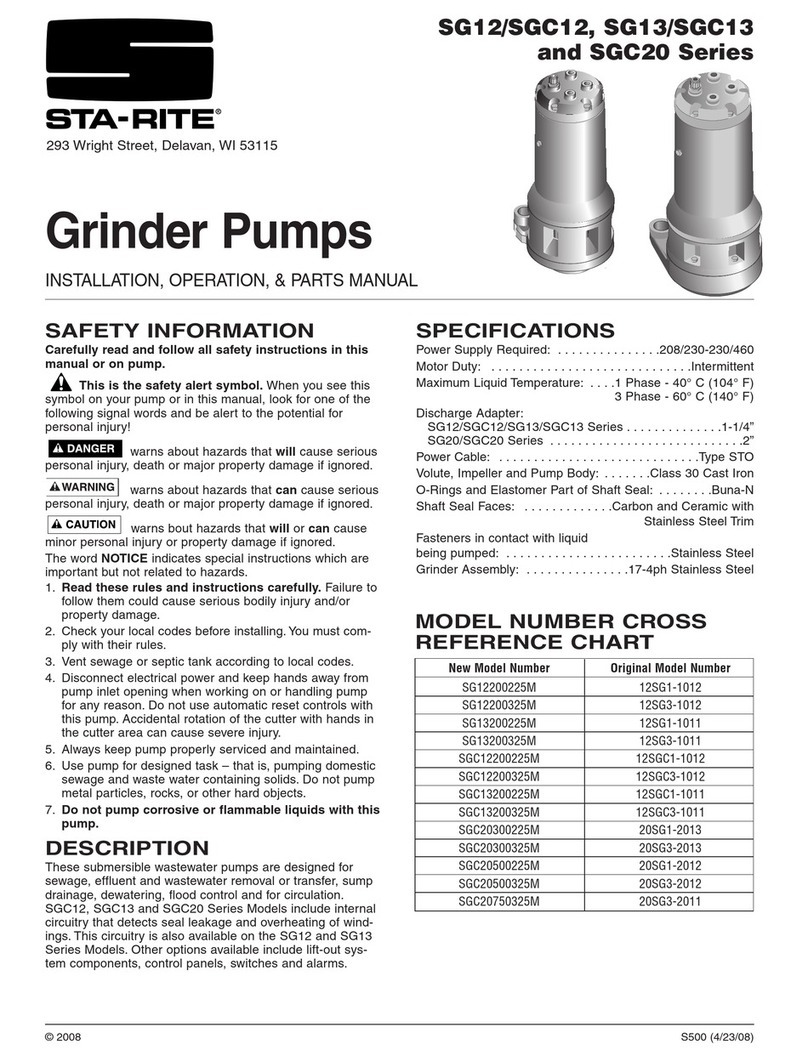
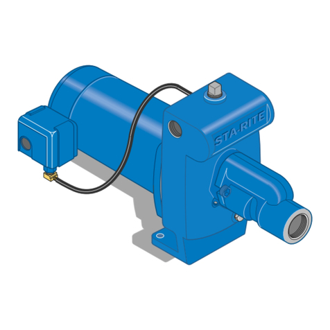
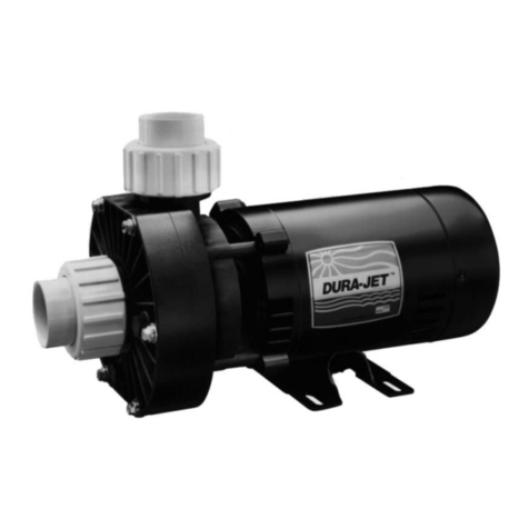
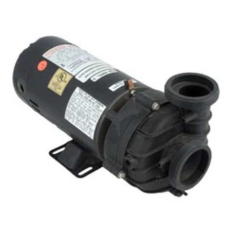
manuals.online logo
Brands
  1. Home
  2. •
  3. Brands
  4. •
  5. STA-RITE
  6. •
  7. Water Pump
  8. •
  9. STA-RITE E440 Series Guide

STA-RITE E440 Series Guide

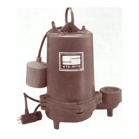
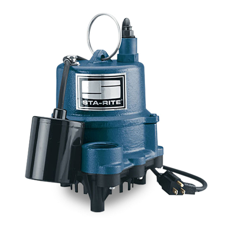
E440 / S440 Series
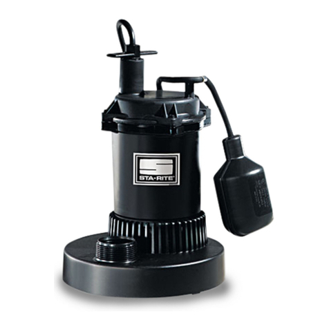
Submersible Solids and
Effluent Handling Pumps
INSTALLATION, OPERATION, & PARTS MANUAL
SAFETY INFORMATION
Carefully read and follow all safety instructions in this
manual or on pump.
This is the safety alert symbol. When you see this
symbol on your pump or in this manual, look for one of the
following signal words and be alert to the potential for
personal injury!
warns about hazards that will cause serious
personal injury, death or major property damage if ignored.
warns about hazards that can cause serious
personal injury, death or major property damage if ignored.
warns about hazards that will or can cause
minor personal injury or property damage if ignored.
The word NOTICE indicates special instructions which are
important but not related to hazards.
1. Read these rules and instructions carefully. Failure to
follow them could lead to serious bodily injury and/or
property damage.
2. Check your local codes before installing. You must com-
ply with their rules.
3. Vent sewage or septic tank according to local codes.
4. Do not install pump in any location classified as
hazardous by the National or Canadian Electrical Code.
Risk of cord damage and electrical
shock. Can burn or kill. Do not lift pump by power
cord. See “Cord Lift Warning” on Page 2.
Hazardous voltage. Can shock, burn,
or cause death. During operation the pump is in water.
To avoid fatal shocks, proceed as follows if pump needs
servicing:
5A. Disconnect the power to the outlet box before unplug-
ging the pump.
5B. Take extreme care when changing the fuses. Do not
stand in water or put your finger in a fuse socket.
5C.Do not modify the cord and plug. When using the cord
and plug, plug into a grounded outlet only. When wiring
to a system control, connect the pump ground lead to
the system ground.
6. Do not run the pump dry. Dry running can overheat the
pump, (causing burns to anyone handling it) and will
void the warranty.
7. Pump normally runs hot. To avoid burns when servicing
pump, allow it to cool for 20 minutes after shut-down
before handling it.
8. In normal service, motor should not need oiling. Motor
has been filled at the factory with a special oil.
DESCRIPTION
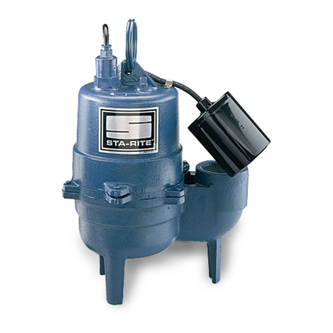
These submersible solid and effluent handling pumps are
designed for waste water removal and for draining ground
water from excavations. All units come with a 3-prong
grounding type power cord. Pump is permanently lubricated
and includes an automatic overload protector in the motor.
© 1999 Sta-Rite Industries, Inc. Printed in U.S.A. S503 (8/3/99)
293 Wright Street • Delavan, WI 53115
GPM (LPM) AT TOTAL FEET (m)
510152025
Model (1.5m) (3m) (4.6m) (6.1m) (7.6m)
CAPACITY GALLONS(L)/MINUTE
E440 65 57 48 38 28 37 Ft.
(246) (216) (182) (144) (106)
(11.3m)
S440 72 52 34 14 – 23 Ft.
(273) (197) (129) (53) (–) (7.0m)
No flow
at height
shown
below
Motor Motor Full Load Cord *Switch Setting in inches (mm)
Series HP Amps Length On Off
E440115T 4/10 8.5 15’ 15"(381) 7"(178)
E440115M 4/10 8.5 15’ – –
S440115T 4/10 10.0 15’ 15-1/2”(394) 7-1/2”(191)
PERFORMANCE
ELECTRICAL & SWITCH SPECIFICATIONS
SPECIFICATIONS
Power Supply Required.....................................115V, 60 HZ
Motor Duty...........................................................Continuous
Liquid temperature Range..............................130° F (55° C)
Circuit Requirement.................................................15 Amps
Discharge Pipe Size..............................................2” (51mm)
INSTALLATION
NOTICE: Install pump on a hard, level surface (cement,
asphalt, etc.). Never place pump directly on earth, clay or
gravel surfaces. Basin must be at least 13” (330mm) in diam-
eter. Be sure that switch can swing through its entire arc
without any obstruction.
Piping
Effluent Applications (for 3/4" (19.1mm) or less solids)
Piping must be 1-1/2" (38.1mm) minimum to carry volume of
pump discharge. Check local codes to determine if a check
valve is required in your system. In cold climates, check
valves are not used to prevent effluent from freezing in pip-
ing.
If using as sump pump, a check valve is recommended.
Sewage Applications (for 2" (51mm) or less solids)
In any case, piping must not be smaller than pump dis-
charge.
When installed in a sewage system, pipe must be capable of
handling semi-solids of at least 2" (51mm) diameter.
The rate of flow in the discharge pipe must keep any solids
present in suspension in the fluid. To meet minmimum flow
requirements (2 feet (.6 m) per second in discharge line) size
pipe as follows:
A Pipe Size Of: Will Handle a Flow Rate Of:
1-1/2" (38.1mm) 12 GPM (45 LPM)
2" (51mm) 21 GPM (79 LPM)
2-1/2" (63.5mm) 30 GPM (114 LPM)
3" (76.2mm) 48 GPM (182 LPM)
Use a 2" (51mm) swing check valve in pump discharge to
prevent backflow of liquid into sump basin. Check valve
should be a free flow valve that will easily pass solids.
NOTICE: For best performance of check valve when han-
dling solids, do not install it with discharge angled more than
45° above the horizontal. Do not install check valve in a ver-
tical position as solids may settle in valve and prevent open-
ing on startup.
Drill a 3/16" (4.8mm) hole in discharge pipe about 1–2"
(25.4 - 51mm) above pump discharge connection (but below
check valve) to prevent airlocking the pump.
Electrical
Hazardous voltage. Can shock, burn, or
cause death. When installing, operating, or servicing this
pump, follow safety instructions listed below.
1. DO NOT splice the electrical power cord.
2. DO NOT allow electrical cord plug to be submerged.
3. DO NOT use extension cords. They are a fire hazard
and can reduce voltage sufficiently to prevent pumping
and/or damage motor.
4. DO NOT handle or service pump while it is connected to
power supply.
5. DO NOT remove grounding prong from plug or modify
plug. To protect against electrical shock, the power cord
is a three-wire conductor and includes a 3-prong ground-
ed plug. Plug pump into a 3-wire, grounded, grounding-
type receptacle. Connect pump according to electrical
codes that apply.
For automatic operation, plug or wire pump into an automatic
float switch or duplex controller. For manual operation plug
pump directly into an electrical outlet.
Connect or wire pump to its own circuit with no other outlets
or equipment in the circuit. Size fuses or circuit breakers
according to the Electrical and Switch Specifications Chart,
on Page 1.
Risk of electrical shock and fire. Be sure
that power supply information (Voltage/ Hertz/Phase) on
pump motor nameplate matches incoming power supply
exactly. Install pump according to all electrical codes that
apply.
OPERATION
NOTICE: Do not allow pump to run in a dry sump. It will void
the warranty and may damage the pump.
An automatic overload protector in the motor will protect
motor from burning out due to overheating/overloading.
When motor cools down, overload protector will automatically
reset and start motor.
If overload trips frequently, check for cause. It could be a
stuck impeller, wrong/low voltage, or electrical failure in
motor. If an electrical failure in the motor is suspected,
replace pump.
Pump is permanently lubricated. No oiling or greasing is
required.
2
1. Attempting to lift or support pump by
power cord can damage cord and
cord connections.
2. Cord may pull apart, exposing bare
wires with possibility of fire or electri-
cal shock.
3. Lifting or supporting pump by power
cord will void warranty.
4. Use lifting ring or handle on top of
pump for all lifting/lowering of pump.
Disconnect power to pump before
doing any work on pump or attempt-
ing to remove pump from sump.
1476 0195
Risk of electrical shock.
Can burn or kill.
Do not lift pump by
power cord.
WARNING
MAINTENANCE
General
Hazardous voltage. Can shock, burn, or
cause death. Before removing pump from basin for ser-
vice, always disconnect electrical power to pump and
control switch.
Submerge complete pump in a disinfectant solution
(chlorox or chlorine) for at least one hour before disas-
sembling pump.
The pump motor contains a special lubricating oil which
should be kept clean and free of water at all times.
Impeller Replacement
1. Unplug cord from power source.
2. Remove screws from lower volute housing (Key #1)
and separate volute halves.
3. Hold shaft with screwdriver in slot in end of shaft;
unscrew impeller (Key #2) counterclockwise from
shaft.
4. Thread new impeller onto shaft. Hold shaft with
screwdriver and tighten impeller firmly hand tight.
5. Remount lower volute housing (Key #1).
6. Plug in unit.
7. Pump is ready for operation. To avoid flooding, test
pump before operating by filling sump and running
pump through one complete cycle to be sure that
switch works.
3
Key Part E440115T E440115M S440115T
No. Description Qty 115 Volt 115 Volt 115 Volt
1 Lower Volute 1 PW1-12P PW1-12P PW1-11P
2 Impeller 1 PW5-14P PW5-14P PW5-15P
3 Upper Volute 1 PW1-10P PW1-10P PW1-10P
4 Power Cord 1 PS17-51 PS17-51 PS17-51
5 Automatic Float Switch (Incl. Clamp) 1 PW217-107B – PW217-107B
REPAIR PARTS LIST
IF MOTOR FAILS, REPLACE PUMP.
3
2
1
5
Motor
4
770 0993
EXPLODED VIEW
4
Sudden Starts. If power is on to pump
when thermal overload resets, pump may start without
warning. If you are working on pump, you may get an
electrical shock or impeller may catch fingers or tools.
Disconnect power before servicing pump.
A. Pump fails to operate: 1. Check to be sure that power cord is securely plugged into outlet.
Disconnect power to outlet before handling pump or motor.
2. Check to be sure you have electrical power.
3. Check that liquid fluid level is high enough to activate switch or controller.
4. Check to be sure that there is a 3/16" (4.8mm) vent hole in discharge pipe and
it is not plugged.
5. Check for blockage in pump inlet, impeller, check valve or discharge pipe.
6. Thermal overload may have tripped. Test start pump; if it starts and then
stops immediately, disconnect from power source for 30 minutes to allow
motor to cool, then reconnect to power source. Check for cause of
overheating/overloading.
B. Pump fails to empty sump: 1. Be sure all valves in discharge pipe are fully open.
2. Clean out discharge pipe and check valve.
3. Check for blockage in pump inlet or impeller.
4. Pump not sized properly. A higher capacity pump may be required.
C. Pump will not shut off: 1. Check automatic float switch or controller for proper operation and
location. See manufacturer’s installation instructions for switches/controller.
2. If pump is completely inoperative or continues to malfunction, consult your
local serviceman.
TROUBLES-REMEDIES
LIMITED WARRANTY
Sta-Rite Industries, Inc., warrants to the original consumer of the products listed below, that they will be free from defects in
material and workmanship for the Warranty Period from the date of original installation or manufacture as noted.
Product Warranty Period
Water Systems Products – jet pumps,
whichever occurs first:
small centrifugal pumps, submersible pumps 1 year from date of original installation, or
and related accessories 2 years from date of manufacture
Hydro-Flow Filters 1 year from date of purchase
Signature 2000 Fibrewound Tanks 5 years from date of original installation
Pro-Source Steel Pressure Tanks 5 years from date of original installation
Pro-Source Epoxy-Line Tanks 3 years from date of original installation
Sump/Sewage/Effluent Products 1 year from date of original installation, or
2 years from date of manufacture
Our warranty will not apply to any product that has been subject to negligence, misapplication, improper installation or main-
tenance. In the event a three phase submersible motor is operated with single phase power through a phase converter, or if
three-leg ambient compensated, extra-quick trip overload relays of recommended size are not used, our warranty is void.
Buyer’s only remedy and Sta-Rite Industries, Inc.’s only duty is to repair or replace defective products (at Sta-Rite Industries,
Inc.’s choice). Buyer agrees to pay all labor and shipping charges associated with this warranty and to request warranty ser-
vice through the installing dealer as soon as a problem is discovered. If warranty service is requested more than 30 days after
the Warranty Period has ended, it will not be honored.
STA-RITE INDUSTRIES, INC. SHALL NOT BE LIABLE FOR ANY CONSEQUENTIAL, INCIDENTAL, OR CONTINGENT
DAMAGES WHATSOEVER.
THE FOREGOING WARRANTIES ARE EXCLUSIVE AND IN LIEU OF ALL OTHER EXPRESS WARRANTIES. IMPLIED
WARRANTIES, INCLUDING BUT NOT LIMITED TO THE IMPLIED WARRANTIES OF MERCHANTABILITY AND FITNESS
FOR A PARTICULAR PURPOSE, SHALL NOT EXTEND BEYOND THE WARRANTY PERIOD PROVIDED HEREIN.
Certain states do not permit the exclusion or limitation of incidental or consequential damages or the placing of limitations on
the duration of an implied warranty, therefore, the limitations or exclusions herein may not apply. This warranty sets forth spe-
cific legal rights and obligations, however, additional rights may exist, which may vary from state to state.
Supersedes all previous publications.
Sta-Rite Industries, Inc. 293 Wright St., Delavan, WI 53115

This manual suits for next models

4

Other STA-RITE Water Pump manuals

STA-RITE SG11200 Series User manual

STA-RITE

STA-RITE SG11200 Series User manual

STA-RITE PC13316V-01 Guide

STA-RITE

STA-RITE PC13316V-01 Guide

STA-RITE DURA-JET 5DJAFB-0001 User manual

STA-RITE

STA-RITE DURA-JET 5DJAFB-0001 User manual

STA-RITE DURA-GLAS P2R Series Guide

STA-RITE

STA-RITE DURA-GLAS P2R Series Guide

STA-RITE DURA-JET 5JTAC-A User manual

STA-RITE

STA-RITE DURA-JET 5JTAC-A User manual

STA-RITE DB10018T User manual

STA-RITE

STA-RITE DB10018T User manual

STA-RITE 300E Series User manual

STA-RITE

STA-RITE 300E Series User manual

STA-RITE D Series User manual

STA-RITE

STA-RITE D Series User manual

STA-RITE LT Series User manual

STA-RITE

STA-RITE LT Series User manual

STA-RITE PE Series User manual

STA-RITE

STA-RITE PE Series User manual

STA-RITE TPEA Series User manual

STA-RITE

STA-RITE TPEA Series User manual

STA-RITE US425125M-01 Guide

STA-RITE

STA-RITE US425125M-01 Guide

STA-RITE MPRA6D-146L Guide

STA-RITE

STA-RITE MPRA6D-146L Guide

STA-RITE S5P1R-VS User manual

STA-RITE

STA-RITE S5P1R-VS User manual

STA-RITE DYNA-WAVE MPRA Series User manual

STA-RITE

STA-RITE DYNA-WAVE MPRA Series User manual

STA-RITE ABG Series User manual

STA-RITE

STA-RITE ABG Series User manual

STA-RITE HC-01 User manual

STA-RITE

STA-RITE HC-01 User manual

STA-RITE Max-E-Pro Series User manual

STA-RITE

STA-RITE Max-E-Pro Series User manual

STA-RITE DURA-JET 5JSAC-A User manual

STA-RITE

STA-RITE DURA-JET 5JSAC-A User manual

STA-RITE C Series User manual

STA-RITE

STA-RITE C Series User manual

STA-RITE Dura-Jet User manual

STA-RITE

STA-RITE Dura-Jet User manual

STA-RITE DPC User manual

STA-RITE

STA-RITE DPC User manual

STA-RITE Signature 2000 User manual

STA-RITE

STA-RITE Signature 2000 User manual

STA-RITE DC13318V User manual

STA-RITE

STA-RITE DC13318V User manual

Popular Water Pump manuals by other brands

SKC AirChek XR5000 operating instructions

SKC

SKC AirChek XR5000 operating instructions

Bosch Rexroth 11 Series instruction manual

Bosch

Bosch Rexroth 11 Series instruction manual

Alcatel IPUP A100 instruction manual

Alcatel

Alcatel IPUP A100 instruction manual

Xylem Bell & Gossett e-82SC instruction manual

Xylem

Xylem Bell & Gossett e-82SC instruction manual

Super Ego RP50-S Directions for use

Super Ego

Super Ego RP50-S Directions for use

Ingersoll-Rand ARO 650408-X-B Operator's manual

Ingersoll-Rand

Ingersoll-Rand ARO 650408-X-B Operator's manual

Lincoln SKF FlowMaster II A Series Operation guide

Lincoln

Lincoln SKF FlowMaster II A Series Operation guide

DAB E.SYBOX MINI 3 Instruction for installation and maintenance

DAB

DAB E.SYBOX MINI 3 Instruction for installation and maintenance

Hydromatic SHEF100 Installation and operator's manual

Hydromatic

Hydromatic SHEF100 Installation and operator's manual

Power-flo PFSE51 Series Installation, service & parts manual

Power-flo

Power-flo PFSE51 Series Installation, service & parts manual

GORMAN-RUPP PUMPS SF4B Installation, operation and maintenance manual

GORMAN-RUPP PUMPS

GORMAN-RUPP PUMPS SF4B Installation, operation and maintenance manual

sauermann Si-10 Assembling Instruction

sauermann

sauermann Si-10 Assembling Instruction

WOERNER GMG-LEZ Translation of the original operation manual

WOERNER

WOERNER GMG-LEZ Translation of the original operation manual

GORMAN-RUPP PUMPS PA Series Installation, operation and maintenance instructions manual

GORMAN-RUPP PUMPS

GORMAN-RUPP PUMPS PA Series Installation, operation and maintenance instructions manual

ARVEN TURBO-LG operating instructions

ARVEN

ARVEN TURBO-LG operating instructions

PYD Electrobombas POOL Series Operating and maintenance manual

PYD Electrobombas

PYD Electrobombas POOL Series Operating and maintenance manual

Pfeiffer Vacuum MVP 020-3 AC operating instructions

Pfeiffer Vacuum

Pfeiffer Vacuum MVP 020-3 AC operating instructions

ProMinent gamma/l Installation and configuration manual

ProMinent

ProMinent gamma/l Installation and configuration manual

manuals.online logo
manuals.online logoBrands
  • About & Mission
  • Contact us
  • Privacy Policy
  • Terms and Conditions

Copyright 2025 Manuals.Online. All Rights Reserved.