Stabila Laser LA-P+L User manual

Laser LA-P+L
LA-P+L-A 05/99 32 14097
Please read these instructions before use!
GB

2 - 9
10 - 17
18 - 25
26 - 33
34 - 41
D
GB
F
I
E
42 - 49
NL
1
12
4b
4a
7
1
3
25 6
11
8
10
11
9

Operating instructions
The STABILA levelling and line laser LA-P+L is an easy-to-use laser unit
which self-adjusts in the range of +5°. It permits both levelling and fast,
precise vertical alignment.
We have tried to explain the handling and functioning of the unit in an
easy-to-understand and logical way. If, however, you still have any questi-
ons, please do not hesitate to contact us for further advice on the following
phone numbers:
GB
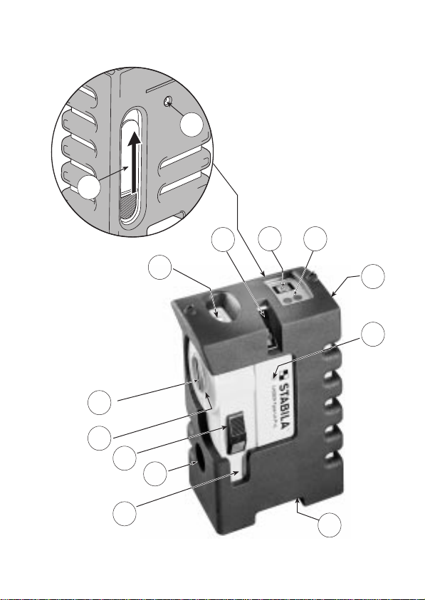
Elements of the unit
GB 01-21-7057987 01-8362828 847-4880050
IRL
USA
10
E.mail: [email protected]
(1) Exit aperture for spot
(2) Exit aperture for vertical laser line
(3) Vial for transverse inclination control
(4) a) On switch
b) Off switch ( Transport lock )
(5) Selection switch (Spot/Line)
(6) LEDs for measuring range indication (red), status on/off (green)
(7) Prism holder
(8) Protective cover
(9) Battery compartment cover
(10) Tripod connecting thread
(11) Suspension eyelets
(12) Cover plugs

N.B.
When using Class 2 laser instru-
ments, the lid-closing reflex protects
the eye against accidental short term
eye contact with the laser beam.
These units can therefore be used
without additional protective measu-
res. Nevertheless, you should not
look directly into the laser beam.
a) Levelling
Place the unit on a firm base so that the bubble of the transverse vial (3)
does not touch the edge of the vial. To ensure that the self-levelling range
is not exceeded during all-round measurement, rotate the unit by 90° and
check that the transverse vial does not touch the edge. This vial is solely
used to check that the transverse inclination does not exceed 5°. If the
admissible longitudinal inclination is exceeded, the laser starts to flash.
Set the On/Off switch to position (4a). Switch over to spot mode by pres-
sing the selection switch (5).
The laser aligns itself automatically and can be set to the desired direction
simply by rotating it on the base surface.
Always rotate the unit as close to the centre as possible to ensure that no
incorrect measurements are caused by parallel offset on sloping surfaces.
Keep out of the reach of children!
Main applications:
The laser spectacles available with our laser instruments are not goggles
(i.e. for protection). They serve for a better visibility of the laser light!
EN 60825-1:97-03
11

c) Finding plumb points
b) Marking vertical lines
Set On/Off switch (4) to position (4a). Simply place the unit on the floor in
front of the desired point on the wall (check transverse inclination on the
vial); the unit projects a vertical line onto the wall. If the inclination in the
longitudinal direction of the unit is excessive, the laser starts to flash.
d) Marking of Vertical Planes
(vertical levelling)
(using beam separator penta prism = optional extra)
Creating reference planes at a right angle to the horizontal reference plane.
There are many applications, and these can be divided into two basic me-
thods. To this end, attach the prism and set up the unit so that the direction
of the vertical laser plane defined by the prism is aligned roughly parallel to
or at a right angle to the wall.
1.
2.
12
Set up the laser so that the first 50 cm of the laser line on the floor, for ex-
ample, meet the point which is to be transferred to the ceiling. Accordingly,
mark the last visible 50 cm of the laser line on the ceiling.
Move the unit so that the first 50 cm of the laser line on the floor meet the
point again, but (for example) offset by 90° relative to the first position.
The point at which the laser line intersects the marked line is the sought
plumb point.
(points on a vertical plumb line between floor and ceiling or vice-versa)

At a right angle to wall:
Creatingverticalreference planes;
e.g. for positioning of partitions
Parallel to the wall:
e) Alignment
(Setting screw connections, plugged boreholes etc. to the same height)
For rapid marking of points at the same height, the unit can be hung on the
wall via the suspension eyelets (11) on a nail or screw (for example) at the
desired height. By inserting the following screws or the drill directly in the
laser beam, the user can ensure fast screw connections at the identical
height without the need to mark the position.
Positioning of tiles, panels,parquet
(floor, ceiling, wall), marking of
right angles simply by swivelling
Swivel until
S1 = S2
Swivel until S1 = S2
Deflection
beam
Continuous beam
Deflection
beam
Continuous
beam
13
S1
S2

Checking calibration
The automatic spot and line laser LA-P+L is designed for on-site use and left our
company in perfectly adjusted condition. As with any precision instrument, how-
ever, it is necessary to check calibration at regular intervals. Each time before
starting work, particularly if the unit has been exposed to vibrations, you should
check the calibration.
If the unit has been subjected to impacts, you should check the calibration over
the entire self-levelling range.
a) Checking spot calibration
The accuracy of the system is 3 mm over 10 metres or 0.3 mm/metre in the
self-levelling range of +5°.
Set up the unit in a room directly in front of a wall with the spot exit aper-
ture pointing towards wall A. (Ensure that the bubble of the transverse vial
does not contact the edge.) Mark the centre of the laser spot on wall A
(point (1)).
Rotate the unit by 180° and mark the centre of the laser spot on wall B
(point (2)).
Set up the unit in front of the opposite wall B with the spot exit aperture
pointing towards wall B. Align the laser so that the centre of the laser spot
exactly coincides with point (2).
Rotate the unit on the base surface by 180° and mark the new point (3) on
wall A.
If the two walls A and B are 10 metres apart, the distance between points
(1) and (3) must not exceed 6 mm 2 x 3 mm / 10 metres. If the distance
is greater than this, the unit can be adjusted as described below.
14

Adjustment
As described in the section “Checking spot calibration”, mark the deviation
of the laser using the points (1) and (3) on a wall. If no alterations have
been made to the laser beam, the corresponding target point is exactly
between the two points.
• Remove the cover plug (12). Secure the pendulum (4) using the
transport lock (position 4b).
• Use a screwdriver to adjust the adjusting screws through the opening.
Turning the adjusting screw in a clockwise direction moves the beam
upwards, while turning anticlockwise moves it downwards.
• Loosen the transport lock (4) and check the adjustment. If the centre-
point of the beam is exactly between the two points (1) and (3), the laser
is accurately adjusted.
• Check the calibration once again as described in the section “Checking
spot calibration”.
b) Checking line calibration
To perform this check, you must first generate a reference - for example,
by fixing a plumb line near to a wall or by marking several points vertically
below one another using the beam separator prism (optional extra) after
checking spot calibration.
Set up the unit in front of the reference mark (plumb line or points) and
compare the beam with the reference. The deviation between the centre of
the line and the reference mark should not exceed 1 mm over a line length
of 2 metres.
N.B.
If the deviation is excessive (e.g. following the effect of impact on the unit)
despite the fact that the spot calibration is inside the tolerance, the unit
should be taken to the dealer in the original case for repair.
15
Battery changing
Push the battery compartment cover in an upward direction and remove.
Slightly pull out the battery holder. Pull off the clip-on contacts and remove
the battery holder. Insert new batteries in accordance with the instructions
in the battery holder. Only use 1.5 V mignon (size AA) batteries.

Care and maintenance
• Soiled windows on the laser beam aperture have a negative influence on
the quality of the beam; clean using a soft cloth (use glass cleaning de-
tergent if necessary).
• Clean the unit using a moist cloth. Never spray or immerse in liquid! Do
not use solvents or thinners!
Handle the spot and line laser LA-P+L with extreme care - as you would
any precision optical instrument.
Technical data
Laser type: red diode laser, wavelength 635 nm,
output < 1 mW, laser class 2
in line with EN 60825 -1 : 97 - 03
Self-levelling range: approx. +5° in longitudinal direction with a
transverse inclination < 5°
Levelling accuracy: +0.3 mm/metre
Batteries 3 x 1.5 V size AA mignon batteries
Operating life: approx. 30 hours
Operating temperature range: 0°C to +40°C
The unit starts to turn itself off automati-
cally at temperatures > 40°C
Storage temperature range: -20°C to +60°C
Subject to technical modification.
16

Warranty terms
STABILA extends a warranty for defects and the absence of assured pro-
perties of the unit resulting from material or production faults for a period of
12 months from date of purchase. Remedy of defects is effected at
STABILA’s own discretion by repair or replacement of the unit. STABILA is
not liable for any claims extending beyond the above.
Liability is excluded by defects caused by incorrect handling (e.g. damage
due to dropping, operating using incorrect voltage/current, use of unsuitable
power sources) as well as by modifications to the unit effected by the user
or third parties.
Moreover, no liability is assumed for natural wear and tear or for minor
defects which do not impair functioning of the unit to any great degree.
Please initiate warranty claims by taking the unit to your dealer together
with the completed warranty certificate (see last page).
17

Kunde:
Customer:
Client:
Cliente:
Cliente:
Klant:
Kaufdatum:
Date of purchase:
Date d'achat:
Data d'acquisto:
Fecha de compra:
Aankoopdatum:
Garantieschein für STABILA-Laser LA-P+L
Warranty Certificate for STABILA Laser LA-P+L
Bon de garantie du Laser LA-P+L STABILA
Cartolina di garanzia per laser LA-P+L STABILA
Certificado de garantía para el STABILA laser LA-P+L
Garantiebewijs voor STABILA laser LA-P+L
Händler (Stempel, Unterschrift)
Dealer (stamp, signature)
Revendeur (cachet, signature)
Timbro e firma del rivenditore
Comerciante (selo, assinatura)
Handelaar (stempel, handtekening)
Adresse:
Address:
Adresse:
Indirizzo:
Endereço:
Adres:
--------------------------------------------------------------------
I
F
GB
D
E
NL

STABILA Messgeräte
Gustav Ullrich GmbH & Co. KG
P.O. Box 13 40 / D-76851 Annweiler
Landauer Str. 45 / D-76855 Annweiler
Tel.: +49-63 46 30 90
Fax: +49-63 46 30 989
Table of contents
Other Stabila Laser Level manuals

Stabila
Stabila Laser LAR 120 G User manual

Stabila
Stabila LA-5PG User manual

Stabila
Stabila LAR-200 User manual

Stabila
Stabila Laser FLS 90 User manual

Stabila
Stabila LAPR-150 User manual

Stabila
Stabila OLS 26 User manual

Stabila
Stabila LAR-250 User manual

Stabila
Stabila LA 90L User manual

Stabila
Stabila 196 electronic IP65 User manual

Stabila
Stabila LAX 300 G User manual


