Stagnoli ALPHEO 230V User manual


Istruzioni, instructions Instrucciones
4
Il presente manuale è destinato solamente al personale tecnico qualificato per l’installazione
e non all’utilizzatore finale; è compito dell’installatore informare successivamente
l’utilizzatore, sulle modalità d’uso dell’automatismo, sui possibili pericoli che ne possono
derivare e sulla necessità di una manutenzione periodica.
L’installazione deve essere effettuata solo da personale qualificato e rispettando le vigenti
normative riguardanti le chiusure automatizzate. In particolare la conformità
dell’installazione prevede il rispetto della direttiva 89/392 e delle norme EN 12453 e EN
12445.
ALPHEO è stato realizzato appositamente per gestire l’automazione di cancelli a battente,
quindi, è vietato utilizzare il prodotto per scopi diversi da quelli previsti o in modo improprio.
Utilizzare componenti originali. La ditta Stagnoli non si assume alcuna responsabilità per
danni dovuti all’utilizzo di componenti non originali.
Accertarsi che la struttura del cancello sia solida e adatta ad essere motorizzata.
Accertarsi che il cancello durante il suo movimento non subisca punti di attrito, ne abbia la
possibilità di deragliare .
Prima di intervenire sul dispositivo, assicurarsi che l’alimentazione sia staccata.
Collegare il cavo della tensione solo a linee di alimentazione dotate di adeguate protezioni
elettriche; in particolare prevedere un dispositivo per assicurare la disconnessione
onnipolare dalla rete, con una distanza tra i contatti di almeno 3.5 mm.
Valutare con particolare attenzione i dispositivi di sicurezza da installare ed il luogo in cui
devono essere posizionati, inoltre, inserire sempre un dispositivo di arresto di emergenza che
permetta il distacco obbligato dell’alimentazione.
Le operazioni di manutenzione e in particolare l’accesso alle parti interne del motoriduttore
devono essere svolte solo ed esclusivamente da personale qualificato.
L’irreversibilità del motoriduttore evita l’installazione di elettroserrature e, in caso di black-out,
il dispositivo di sblocco (protetto da chiave personalizzata) permette di aprire e di chiudere il
cancello manualmente. L’utilizzo dell’elettroserratura è comunque consigliato per assicurare
una chiusura più efficace, soprattutto nel caso di battenti di lunghezza superiore ai 2.5 metri.

Istruzioni, instructions Instrucciones
5
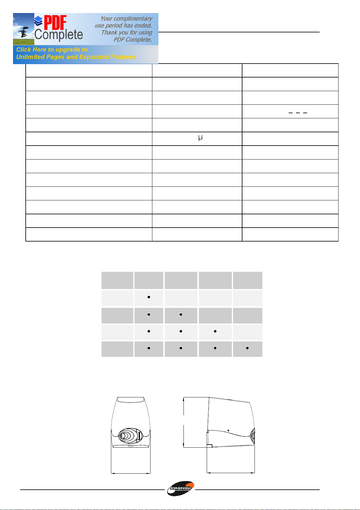
Caratteristiche tecniche ALPEHO
Dati tecnici ALPHEO 230V ALPHEO 24V
Alimentazione 230V~ (50 Hz) 230V~ (50 Hz)
Corrente assorbita max.(A) 1,3 1
Alimentazione motore 230V~ 24V –––––
Potenza assorbita max. (W) 160 W 120 W
Condensatore 10 F -
Tempo manovra 90° (sec) 16 - 20 16 - 20
Coppia 180 Nm 180 Nm
Temperatura operativa (°C) -20 … +60 -20 …+60
Termoprotezione (°C) 150 -
Ciclo di lavoro (%) 30 70
Livello di protezione IP 44 44
Peso* (Kg) 9 10
Limiti di impiego
Ingombri
209 256
263
ANTA 1 m 1.5 m 2 m 2.3 m
300 kg
250 kg
225 kg
200 kg

Istruzioni, instructions Instrucciones
6
Verifiche preliminari
Controllare che la struttura del cancello sia sufficientemente robusta e che non ci siano punti
di attrito.
Controllare che le cerniere del cancello siano efficienti e siano adeguatamente lubrificate.
Verificare che ci sia un fermo meccanico d’arresto in chiusura per evitare l’oltrecorsa
dell’anta;
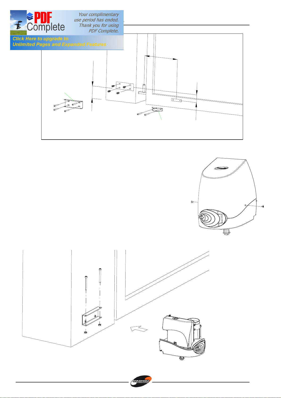
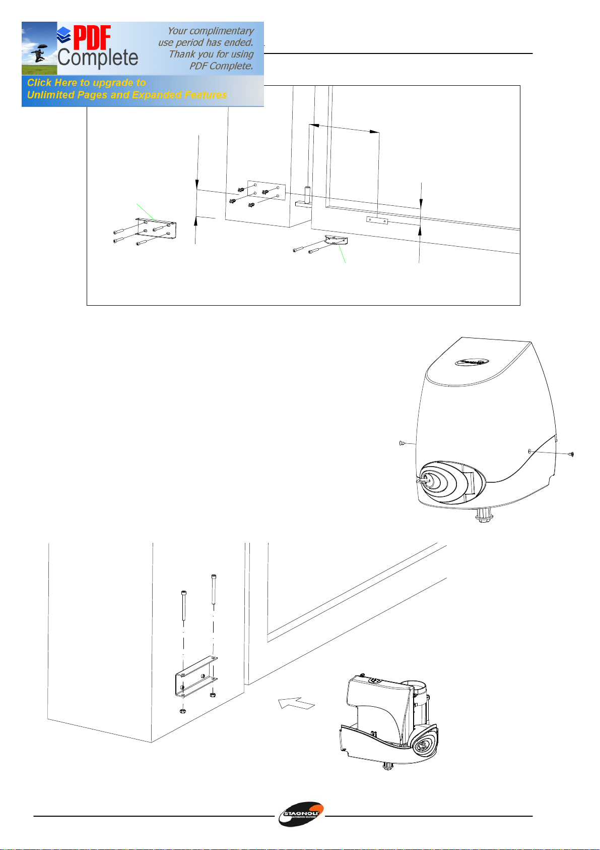
Fissaggio delle staffe al pilastro e al cancello (Figura 1 e figura 2)
Dopo aver verificato le condizioni ottimali per l’installazione, fissare la Piastra Base al pilastro con
tasselli 14 e viti M8 rispettando la distanza minima di 100mm da terra; bloccare la Piastra di
aggancio all’anta con viti M6, rispettando le quote indicate e i valori specificati nella tabella 1.
Figura 1
Tabella 1
APERTURA A B C D
90 155 210 0 430 230 max
90 155 210 50 430 230 max
90 155 210 75 430 230 max
90 155 210 100 430 230 max
90 155 210 125 430 230 max
90 155 210 150 400 230 max
90 155 210 175 400 230 max
90 155 210 200 400 230 max
105 190 210 0 430 230 max
105 200 30 430 230 max
Istruzioni, instructions Instrucciones
7
100min.
78
M8M6
C
Piastrabase
Ø14
Piastradi
aggancio
all'anta
Figura 2
Fissaggio del motoriduttore
Svitare le viti 4,2x9,5, quindi togliere il coperchio (figura 3).
Inserire il motoriduttore nella piastra base in corrispondenza
dei fori e bloccarlo con le viti M8x90 e relativi dadi (figura 4).
Figura 3
M8x80
M8
Figura 4
Istruzioni, instructions Instrucciones
8
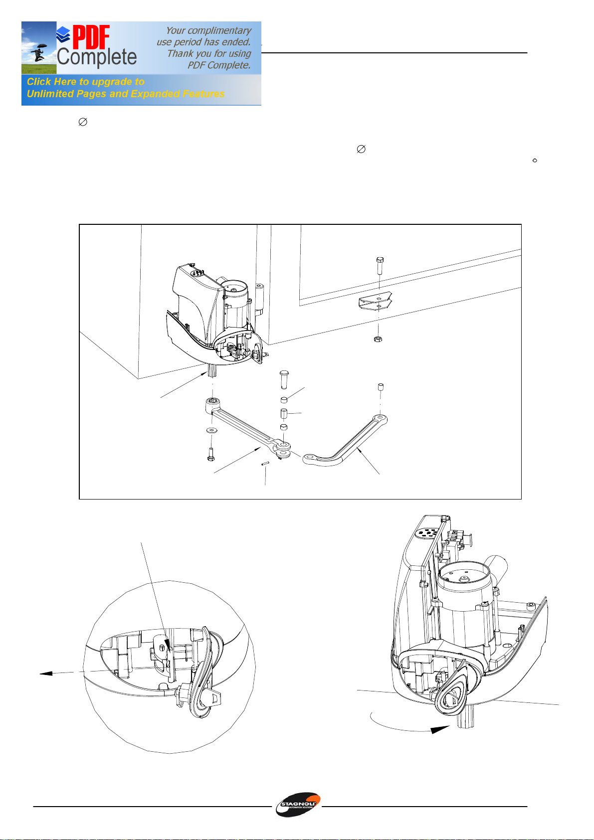
Installazione del braccio snodato (figure 5, 6, 7)
1. Inserire il braccio diritto in corrispondenza dell’albero calettato, posizionare la rondella
11x30 e bloccare il braccio con la vite M10x28.
2. Prendere il braccio curvo, metterlo nella forcella del braccio diritto, introdurre le tre
boccole e il perno, quindi fissare il tutto con la spina 4x24.
3. Sbloccare il motoriduttore girando la chiave in senso orario, aprendo lo sportello di 90 e
tirando la manopola di sblocco.
4. Sull’altra estremita’ inserire la boccola relativa e bloccare il braccio curvo alla staffa del
cancello con la vite M12x40 e relativo dado M12.
Ø11x30
M10x28
SpinaØ4x24
M12x40
M12
BOCCOLA
14-12-15
BOCCOLA
18-16-10
n.2
18-16-15
Albero
Braccio
dritto Braccio curvo
Figura 5
9
0
°
Figura7 Figura 6
Manopola
disblocco
Istruzioni, instructions Instrucciones
9
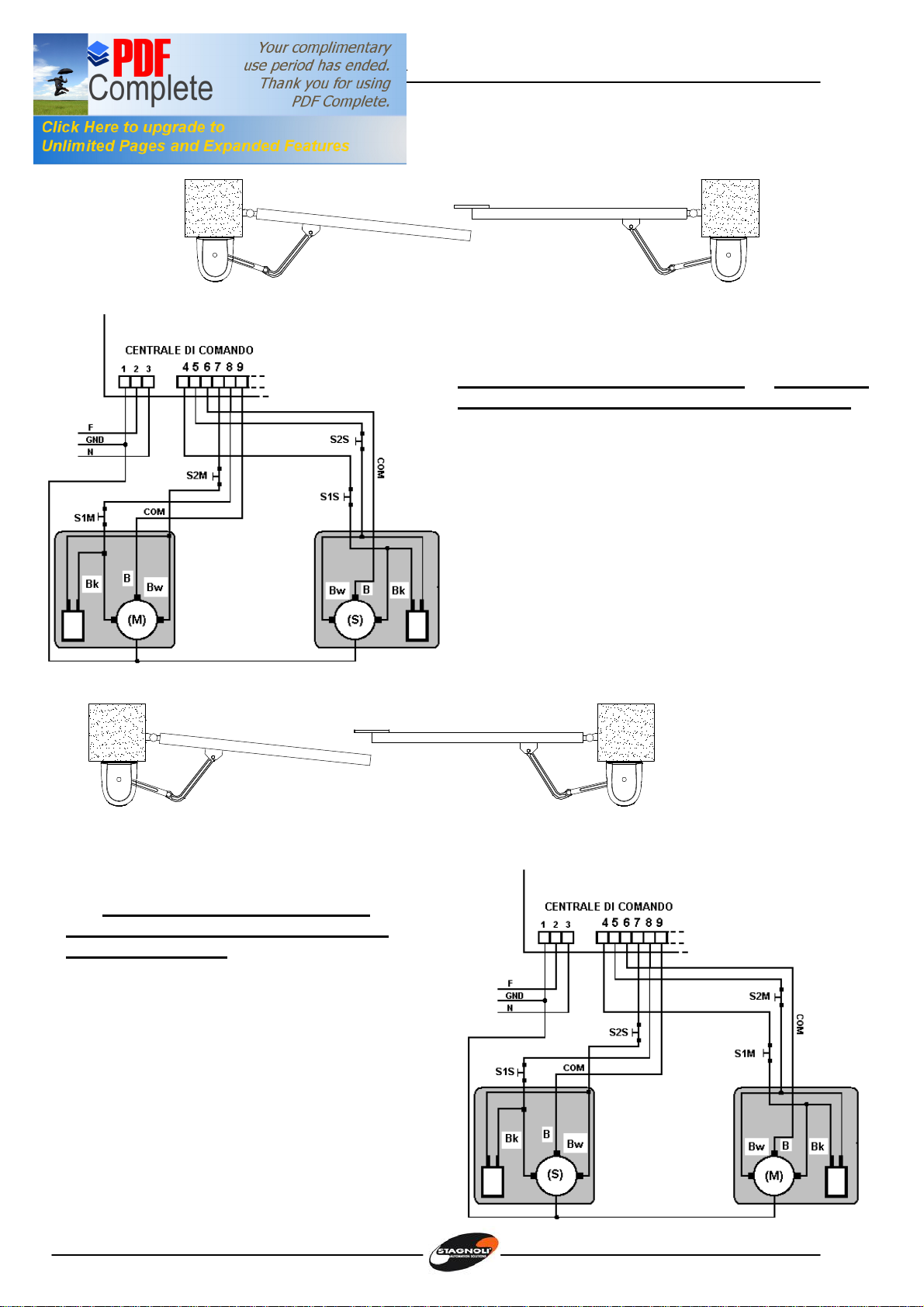
COLLEGAMENTI ELETTRICI ALPHEO 230V
ALPHEO 230 (M)
ALPHEO 230 (S)
SX DX
Collegamenti elettrici per cancello a battenti con
anta sinistra ritardata in chiusura e centrale di
comando sul motore sinistro (ALPHEO 230V (M))
M: motore con centrale di comando (Master)
S: motore senza centrale di comando (Slave)
Bk: cavo motore nero
Bw: cavo motore marrone
B: cavo motore blu
S1M: microinterruttore superiore Master
S2M: microinterruttore inferiore Master.
S1S: microinterruttore superiore Slave
S2S: microinterruttore inferiore Slave
ALPHEO 230 (S) ALPHEO 230 (M)
SX DX
Collegamenti elettrici per cancello a battenti
con anta sinistra ritardata in chiusura e
centrale di comando sul motore destro
(ALPHEO 230V (M)).
M: motore con centrale di comando (Master)
S: motore senza centrale di comando (Slave)
Bk: cavo motore nero
Bw: cavo motore marrone
B: cavo motore blu
S1M: microinterruttore superiore Master
S2M: microinterruttore inferiore Master.
S1S: microinterruttore superiore Slave
S2S: microinterruttore inferiore Slave
Istruzioni, instructions Instrucciones
10
ALPHEO 230 (M)
SX
ALPHEO 230 (S
)
DX
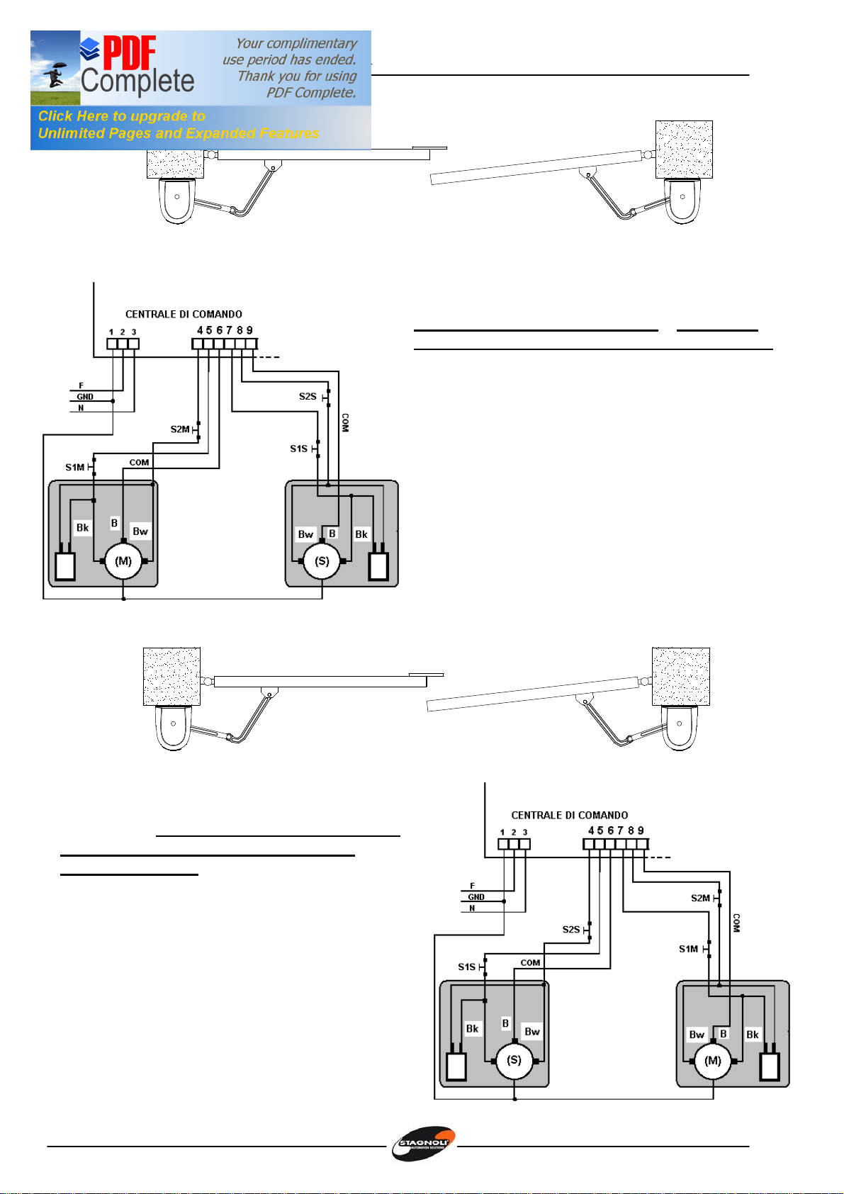
Collegamenti elettrici per cancello a battenti con
anta destra ritardata in chiusura e centrale di
comando sul motore sinistro (ALPHEO 230V (M))
M: motore con centrale di comando (Master)
S: motore senza centrale di comando (Slave)
Bk: cavo motore nero
Bw: cavo motore marrone
B: cavo motore blu
S1M: microinterruttore superiore Master
S2M: microinterruttore inferiore Master.
S1S: microinterruttore superiore Slave
S2S: microinterruttore inferiore Slave
ALPHEO 230 (M)
DX
ALPHEO 230 (S)
SX
DEFAULT - Collegamenti elettrici per cancello a
battenti con anta destra ritardata in chiusura e
centrale di comando sul motore destro
(ALPHEO 230V(M))
M: motore con centrale di comando (Master)
S: motore senza centrale di comando (Slave)
Bk: cavo motore nero
Bw: cavo motore marrone
B: cavo motore blu
S1M: microinterruttore superiore Master
S2M: microinterruttore inferiore Master.
S1S: microinterruttore superiore Slave
S2S: microinterruttore inferiore Slave

Istruzioni, instructions Instrucciones
11
Taratura dei microinterrutori con il motoriduttore montato a sinistra
Apertura:
Con il motoriduttore sbloccato, ruotate l’anta del cancello fino a raggiungere l’apertura
prevista, poi ruotare la camma inferiore in senso orario fino ad attivare il microinterruttore
inferiore, quindi bloccarla con la relativa vite.
microinterrutore
inferiore
Vitedifissaggio
cammainferiore
Camma
inferiore
Chiusura:
Con il motoriduttore sbloccato, portare l’anta nella posizione di chiusura, poi ruotare la camma
superiore in senso antiorario fino ad attivare il microinterruttore, quindi bloccarla con la relativa
vite.
microinterrutore
superiore
Vitedifissaggio
cammasuperiore
Camma
superiore

Istruzioni, instructions Instrucciones
12
Taratura dei microinterrutori con il motoriduttore montato a destra
Chiusura:
Con il motoriduttore sbloccato, ruotate l’anta del cancello fino a raggiungere la chiusura
prevista, poi ruotare la camma inferiore in senso orario fino ad attivare il microinterruttore
inferiore, quindi bloccarla con la relativa vite.
microinterrutore
inferiore
Vitedifissaggio
cammainferiore
Camma
inferiore
Apertura:
Con il motoriduttore sbloccato, ruotate l’anta del cancello fino a raggiungere l’apertura
prevista, poi ruotare la camma superiore in senso antiorario fino ad attivare il microinterruttore
superiore, quindi bloccarla con la relativa vite.
microinterrutore
superiore
Vitedifissaggio
cammasuperiore
Camma
superiore

Istruzioni, instructions Instrucciones
13
Attention!
This manual is for qualified technical personnel only for installation purposes and not
intended for the end user; it’s the installer’s job to explain to the user how the automatism
works, about possible hazards related to it and about the need for periodical
maintenance.
The automatism must be installed by qualified personnel only, observing current standards
concerning automatic closing systems. More specifically, installation conformity calls for
observance of directive 89/392 and standards EN 12453 and EN 12445.
As ALPHEO is made specifically to control swing gates it is forbidden to use the product for
different purposes or improperly.
Use original components only. Stagnoli is not liable for damages if other components are
used.
Make certain that the gate structure is solid and suitable for being motor-driven.
When the gate is moving make sure there are no points of friction and there is no chance
of it derailing.
Make absolutely certain the power is disconnected before carrying out any work on the
device.
Connect the power lead to supply lines with adequate electrical protection only; install a
device to guarantee disconnection of all the phases from the mains that has a distance of
at least 3.5 mm between the contacts.
Pay particular attention when deciding which safety devices to install and their location.
Always install an emergency stop device that will cut power off in the case of necessity.
Only qualified personnel must be allowed to service the unit and access the internal parts
of the geared motor.
Irreversibility of the geared motors means an electric lock does not have to be installed
and, in the case of black-out the release device (protected by a personalised key) lets
you open the gate by hand. We do however recommend using an electric lock to ensure
correct closing especially if the swing gates are longer than 2.5 metres.
Istruzioni, instructions Instrucciones
14
ALPEHO technical specifications
Technical data ALPEHO 230 ALPEHO 24
Supply 230V~ (50 Hz) 230V~ (50 Hz)
Max. current requirement (A) 1.3 1
Motor supply 230V~ 24V –––––
Max. motor power (W) 160 W 120 W
Capacitor 10 F -
90° Travel time (sec) 15 - 20 15 - 20
Torque 180 Nm 180 Nm
Working temperature (°C) -20 … +60 -20 …+60
Thermal overload protection(°C) 150 -
Work cycle (%) 30 70
IP protection level 44 44
Weight* (Kg) 9 10
Utilisation limits
Overall dimensions
209 256
263
Leaf 1 m 1.5 m 2 m 2.3 m
300 kg
250 kg
225 kg
200 kg

Istruzioni, instructions Instrucciones
15
Preliminary checks
Check that the gate structure is sufficiently sturdy and there are no points of friction.
Check the condition of the gate hinges and make sure they are adequately lubricated.
Make sure there is a mechanical stop in closing to prevent the gate going beyond its travel;
Fixing the brackets to the post and gate (Figures 1 and 2)
After having verified the optimum conditions for installation, fix the Base Plate to the post using
14 plugs and M8 screws, observing the minimum distance of 100 mm from the ground. Lock
the fastening plate to the gate with M6 screws, observing the values indicated and those
specified in table 1.
Figure 1
Table 1
OPENING A B C D
90 155 210 0 430 230 max
90 155 210 50 430 230 max
90 155 210 75 430 230 max
90 155 210 100 430 230 max
90 155 210 125 430 230 max
90 155 210 150 400 230 max
90 155 210 175 400 230 max
90 155 210 200 400 230 max
105 190 210 0 430 230 max
105 200 30 430 230 max
Istruzioni, instructions Instrucciones
16
100min.
78
M8M6
C
Piastrabase
Ø14
Piastradi
aggancio
all'anta
Figure 2
Fixing the geared motor
Unscrew the 4.2x9.5 screws and remove the cover (Fig. 3).
Fit the geared motor on the base plate by the holes and
lock it in place with the M8x90 screws and nuts (Fig. 4).
Figure 3
M8x80
M8
Figure 4

Istruzioni, instructions Instrucciones
17
Mounting the articulated arm (Figures 5, 6, 7)
1. the arm must be put in straight by the keyed shaft; position the 11 x30 washer
and lock the arm with the M10x28 screw.
2. Take the curved arm and fit it in the straight arm’s fork; fit the three bushings and
the pin and fasten with the 4 x24 pin.
3. Release the geared motor by turning the key clockwise, opening the door 90° and
pulling the release knob.
4. Fit the bushing on the other end and lock the curved arm to the gate bracket with
the M12x40 screw and M12 nut.
Ø11x30
M10x28
SpinaØ4x24
M12x40
M12
BUSH
14-12-15
BUSH
18-16-10
n.2
18-16-15
SHAFT
STRAIGHT ARM BENDED ARM
Figure 5
9
0
°
Figure 6 Figure 7
Release
Knob

Istruzioni, instructions Instrucciones
18
ELECTRICAL CONNECTIONS
ALPHEO 230 (M)
ALPHEO 230 (S)
SX DX
Electrical connections for a swing gate with the
left leaf delayed in closing and control unit on
the left-hand motor (ALPHEO 230 (M))
M: motor with control unit (Master)
S: motor without control unit (Slave)
Bk: black motor cable
Bw: brown motor cable
B: blue motor cable
S1M: Master top microswitch
S2M: Master bottom microswitch
S1S: Slave top microswitch,
S2S: Slave bottom microswitch,
ALPHEO 230 (S) ALPHEO 230 (M)
SX DX
Electrical connections for a swing gate with
the left leaf delayed in closing and control unit
on the right-hand motor (ALPHEO 230 (M)).
M: motor with control unit (Master)
S: motor without control unit (Slave)
Bk: black motor cable
Bw: brown motor cable
B: blue motor cable
S1M: Master top microswitch,
S2M: Master bottom microswitch,
S1S: Slave top microswitch,
S2S: Slave bottom microswitch,

Istruzioni, instructions Instrucciones
19
ALPHEO 230 (M)
SX
ALPHEO 230 (S
)
DX
Electrical connections for a swing gate with the
right leaf delayed in closing and control unit on
the left-hand motor (ALPHEO 230 (M))
M: motor with control unit (Master)
S: motor without control unit (Slave)
Bk: black motor cable
Bw: brown motor cable
B: blue motor cable
S1M: Master top microswitch,
S2M: Master bottom microswitch,.
S1S: Slave top microswitch,
S2S: Slave bottom microswitch,
ALPHEO 230 (M)
DX
ALPHEO 230 (S)
SX
DEFAULT - Electrical connections for a swing
gate with the right leaf delayed in closing and
control unit on the right-hand motor (ALPHEO
230 (M))
M: motor with control unit (Master)
S: motor without control unit (Slave)
Bk: black motor cable
Bw: brown motor cable
B: blue motor cable
S1M: Master top microswitch,
S2M: Master bottom microswitch.
S1S: Slave top microswitch,
S2S: Slave bottom microswitch.

Istruzioni, instructions Instrucciones
20
Calibrating the microswitches with the geared motor installed on the left
Opening:
With the geared motor released, open the gate to the point wanted; turn the lower cam
clockwise until the lower microswitch trips and then lock it with the relative screw.
Lowermicroswitch
LowerCam
FixingScrew
LowerCam
Closing:
With the geared motor released, close the gate and turn the top cam counter clockwise until
the microswitch trips and then lock it with the relative screw.
UpperMicroswitch
Uppercam
FixingScrew
UpperCam
Other manuals for ALPHEO 230V
1
This manual suits for next models
4
Table of contents
Languages:
Other Stagnoli Engine manuals


Popular Engine manuals by other brands

Emerson
Emerson Leroy-Somer FFB installation guide

TECHTOP
TECHTOP MS1/MS2 Series Installation, operation, maintenance and safety manual

VBrick
VBrick dme Admin guide

Wisconsin
Wisconsin Air Cooled TRA-10D Instruction book and parts list

ModelCraft
ModelCraft Phase3 10,5T operating instructions

Oxygen
Oxygen CASTOR installation manual


