Stahl 5000 Series User manual

5000 Series Owner’s Manual
As of
June 2, 2010
View thousands of Crane Specifications on FreeCraneSpecs.com

2
TABLE OF CONTENTS
5000 SERIES OWNERS MANUAL
s
TABLE OF CONTENTS 2
SAFETY -5
OPERATION 6-9
MAINTENANCE 10-11
SPECIFICATIONS 12
TROUBLESHOOTING 1
MOUNTING INSTRUCTIONS 14-18
PARTS 19-27
SCHEMATICS 28-29
WARRANTY 0
FOR THE LOCATION OF YOUR
FOR THE LOCATION OF YOURFOR THE LOCATION OF YOUR
FOR THE LOCATION OF YOUR NEAREST DISTRIBUTOR CALL 0
NEAREST DISTRIBUTOR CALL 0 NEAREST DISTRIBUTOR CALL 0
NEAREST DISTRIBUTOR CALL 0-
--
-264
264264
264-
--
-7441
74417441
7441
Revision 6/10
View thousands of Crane Specifications on FreeCraneSpecs.com

3
s
SAFETY
5
000
SERIES OWNER’S MANUAL
-
--
- It is YOUR responsibility to maintain and operate this crane safely
It is YOUR responsibility to maintain and operate this crane safely It is YOUR responsibility to maintain and operate this crane safely
It is YOUR responsibility to maintain and operate this crane safely -
--
-
The following words and symbols will be used in your owner’s manual:
! DANGER
DANGER DANGER
DANGER ! Indicates immediate danger and that special precautions are necessary.
! CAUTION
CAUTION CAUTION
CAUTION ! Warns against potential hazards or cautions against unsafe practices.
Your
s
crane is designed to meet all applicable government safety standards. Warranty will be voided if the
crane is misused due to:
• Overloading
• Abuse
• Lack of (or improper) maintenance
• Unauthorized modification
! CAUTION !
! CAUTION !! CAUTION !
! CAUTION !
Operate your 5000 crane within the lifting capacities specified. Exceeding the lifting capacity for a given boom
length can cause tipping or structural failure. Only the
s
“New Machinery and Equipment” warranty shown
on the last page of this manual is valid with this crane. No other warranty—verbal, written, or implied—is valid with
this crane. Treat your
s
crane with respect and service it regularly. These two things can add up to a safer
working environment and longer equipment life.
! CAUTION !
! CAUTION !! CAUTION !
! CAUTION !
Note locations of Danger, Caution, and Lift Capacity decals on the 5000 crane. Read and understand each of
these before attempting to operate the crane. If any of these labels are missing or cannot be read, contact your
s
distributor for immediate replacement.
View thousands of Crane Specifications on FreeCraneSpecs.com

4
s
SAFETY
5000 SERIES OWNER’S MANUAL
GENERAL SAFE OPERATI
GENERAL SAFE OPERATIGENERAL SAFE OPERATI
GENERAL SAFE OPERATING PRACTICES
NG PRACTICESNG PRACTICES
NG PRACTICES
ALWAYS
ALWAYS ALWAYS
ALWAYS inspect your crane daily, prior to use, for malfunctions, defects, or misuse.
ALWAYS
ALWAYS ALWAYS
ALWAYS keep the vehicle as level as possible while loading or unloading.
ALWAYS
ALWAYS ALWAYS
ALWAYS set the vehicle emergency brake before beginning crane operations.
ALWAYS
ALWAYS ALWAYS
ALWAYS keep the load as close to the ground as possible.
ALWAYS
ALWAYS ALWAYS
ALWAYS store the crane and hook when moving the truck.
ALWAYS
ALWAYS ALWAYS
ALWAYS store the controller securely to avoid unauthorized use of the crane.
NEVER
NEVER NEVER
NEVER swing a load that passes over people.
NEVER
NEVER NEVER
NEVER operate the crane within ten feet of a power line.
NEVER
NEVER NEVER
NEVER exceed the rated lifting capacity. Deduct the weight of any load handling equipment from rated capacity.
NE
NENE
NEVER
VER VER
VER leave a load suspended in the air.
NEVER
NEVER NEVER
NEVER use the winch to drag a load into position before lifting.
NEVER
NEVER NEVER
NEVER operate the crane during an electrical storm or when high wind conditions exist.
NEVER
NEVER NEVER
NEVER side load the boom by dragging a load from the side.
NE
NENE
NEVER
VER VER
VER try to service or repair the crane while the crane is operating.
NEVER
NEVER NEVER
NEVER place yourself between the load and truck or other fixed object.
NEVER
NEVER NEVER
NEVER move the truck while operating the crane or with a load on the crane.
SAFETY CHECKLIST
SAFETY CHECKLISTSAFETY CHECKLIST
SAFETY CHECKLIST
STRUCTURAL
STRUCTURALSTRUCTURAL
STRUCTURAL
SOUNDNE
SOUNDNESOUNDNE
SOUNDNESS:
SS: SS:
SS: Inspect the unit for damaged members and loose fasteners.
CONTROLS:
CONTROLS: CONTROLS:
CONTROLS: Make a short test for proper control and operation of all functions.
REPAIRS
REPAIRSREPAIRS
REPAIRS: Fix all problems before using your crane.
LEAKAGE
LEAKAGELEAKAGE
LEAKAGE: Examine all of the hydraulic lines for frays and blisters. Look for signs of lubricating or hydraulic oil
leakage.
HYDRAULIC OIL SUPPLY
HYDRAULIC OIL SUPPLYHYDRAULIC OIL SUPPLY
HYDRAULIC OIL SUPPLY: With the crane in a stored position, and all cylinders retracted, check oil level in the
hydraulic reservoir.
View thousands of Crane Specifications on FreeCraneSpecs.com

5
s
SAFETY
5
000
SERIES OWNER’S MANUAL
DECAL PLACEMENT
DECAL PLACEMENTDECAL PLACEMENT
DECAL PLACEMENT
Note locations of the DANGER, CAUTION, and LIFT CAPACITY decals on s 5000 cranes. Read and
understand each of these decals before attempting to operate your crane. If any decals are missing or cannot be
read, contact your s distributor for immediate replacement.
View thousands of Crane Specifications on FreeCraneSpecs.com

6
s
OPERATION
5000 SERIES OWNER’S MANUAL
LOAD CAPACITIES
LOAD CAPACITIES LOAD CAPACITIES
LOAD CAPACITIES
MEASURED IN POUNDS
MEASURED IN POUNDSMEASURED IN POUNDS
MEASURED IN POUNDS
CRANE RATING :
CRANE RATING : CRANE RATING :
CRANE RATING : 25
2525
25,000 FT./LB.
,000 FT./LB.,000 FT./LB.
,000 FT./LB.
DISTANCE IN FEET
DISTANCE IN FEETDISTANCE IN FEET
DISTANCE IN FEET
NOTE:
NOTE: NOTE:
NOTE: Load capacities are based on 85% of tipping when all outriggers are extended and have
firm contact with a solid surface. Vehicles must have proper axle load distribution and crane
must be mounted in accordance with manufacturer’s instructions.
View thousands of Crane Specifications on FreeCraneSpecs.com

7
s
OPERATION
5
0
00 SERIES
OWNER’S MANUAL
REMOTE CONTROL
REMOTE CONTROLREMOTE CONTROL
REMOTE CONTROL
The crane remote control plugs into a receptacle. The blue line on the male plug on the remote control must line
up with the flat spot on the receptacle at the base of the crane. Push the male plug onto the receptacle while
turning the serrated portion of the male plug clockwise. Continue turning until the pin on the receptacle can be
seen through the hole in the male plug and a “click” is felt.
There are six switches on the remote control. Each is labeled as to the function and direction. For example: To
activate the winch, push up on the switch to “winch up”; push down on the switch to “winch down”.
View thousands of Crane Specifications on FreeCraneSpecs.com

8
s
OPERATION
5000 SERIES OWNER’S MANUAL
The 5000 crane is designed to provide excellent service if operated within the maximum allowable load
specifications stated on the unit’s “Angle Indicator Plate” located on either side of the boom. A load chart is also
included on page 6. Load information charts should be studied before operating the crane. Exceeding the stated
load limit can cause tipping or structural failure. You should familiarize yourself with proper operation procedures
to avoid overloading the crane. As an example: If a load of 4000 pounds is lifted at an 15’ boom length at 75°,
lowering the boom would cause an overload situation.
The 5000 crane is relatively simple to operate. Prior to field use, you should familiarize yourself with the controls
and how the unit reacts to the controls. Practice operations should be performed with a light test weight
progressing to a heavier test weight.
LIFTING OVER
LIFTING OVER LIFTING OVER
LIFTING OVER 2,
2,2,
2,500
500500
500 POUNDS
POUNDS POUNDS
POUNDS
A “two-part” line must be used whenever the load is 2
22
2,
,,
,5
55
500 pounds
00 pounds00 pounds
00 pounds or greater. In order to “two-part” the line:
• Connect the winch cable eye to the pin on the bottom of the manually extendible boom section.
• Insert cable through the snatch block by removing the cotter pin and disassembling.
• Reassemble the snatch block. Be sure to reinsert the cotter pin in the snatch block.
You should also use a “two-part” line for loads under 2,500 pounds if you want to slow down the line speed of
the cable.
LOAD LIFTING
LOAD LIFTINGLOAD LIFTING
LOAD LIFTING
It must be understood that all load ratings are formulated on 85% of tipping. Tipping is defined as a tire breaking
contact with the ground. Further, all load ratings are dependent upon compliance with the following:
• The unit has been correctly installed in accordance with chassis requirements and truck body manufacturer’s
specifications.
• The intended operation is carried out on a level, solid surface with proper outrigger placement.
View thousands of Crane Specifications on FreeCraneSpecs.com

9
s
OPERATION
5
0
00 SERIES
OWNER’S MANUAL
TASK PERFORMANCE
TASK PERFORMANCETASK PERFORMANCE
TASK PERFORMANCE
1. Position the 5000 crane as close to the job as possible on a firm, dry, and level surface. Avoid overhead
obstruction on the work side of the unit.
2. Set the parking brake.
3. Extend and lower the outriggers until firm ground contact is made. On soft ground, use bearing pads to
prevent sinking or tipping.
4. Run the winch line out before extending the boom.
5.
Make sure the connection to the load is secure and will not come loose when lifting the load.
OVERLOAD PROTECTION
OVERLOAD PROTECTIONOVERLOAD PROTECTION
OVERLOAD PROTECTION
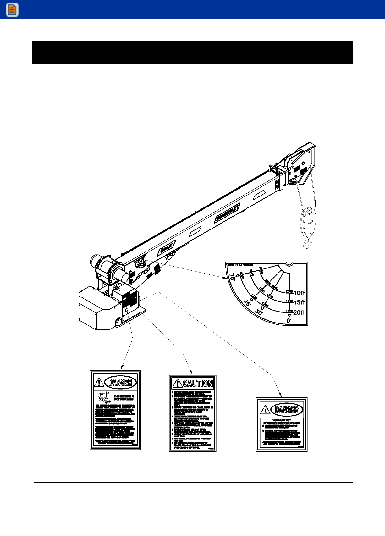
The 5000 crane is equipped with a counterbalance valve inside the lift cylinder to protect against overloading. In
an overload condition, the boom will not elevate. Attempts to winch the load will cause a downward feathering of
the boom until the overload condition is reduced. The counterbalance valve will also keep the boom from coming
down in the unlikely event of a rupture to the hydraulic hoses that supply oil to the lift cylinder.
A pressure sensitive switch is located in the lifting cylinder. It can sense an overload situation. This causes a
shutdown of the winch up, boom extension out, and boom elevation functions, and automatically resets after the
crane has been moved out of the overload position.
An anti-two block feature is provided on the LRX models.
ROTATION STOP
ROTATION STOPROTATION STOP
ROTATION STOP
A stop to prevent the unit from rotating continuously is located on the crane base. The stop is installed so that a
full 60° plus is obtained. A stop lever is attached to the turret and extends so that it will contact the rotation stop
on the base assembly. Do not remove the stop assembly. Continuous rotation will result in damage to the wiring
harness and/or hydraulic hoses.
SPEED CONTROL OPERATION
SPEED CONTROL OPERATIONSPEED CONTROL OPERATION
SPEED CONTROL OPERATION
The boom lift cylinder, extend cylinder, and rotation drive motor are preset at 2 gallons per minute (GPM). This
flow control valve is located in the valve manifold block. The winch function receives the full “required 6 GPM”
flow. An optional proportional flow control valve that controls the crane’s operation speed from 0 to 6 GPM is
available from
s.
RELIEF VALVES
RELIEF VALVESRELIEF VALVES
RELIEF VALVES
The 5000 crane requires a relief valve located at the reservoir to maintain crane operating pressure at 2600 PSI.
This relief valve is not supplied unless using a s hydraulic reservoir. It is the customer’s responsibility to
provide this relief valve when using a reservoir not supplied by s. The main function of this relief valve is
to prevent overloading of the system if the boom is inadvertently rotated against an immovable object, while one
of the other hydraulic functions is also being used. The relief valves would not normally require adjustment, but if
the correct relief valve setting is suspect, refer to the maintenance section of this manual for the proper
adjustment and testing procedure.
View thousands of Crane Specifications on FreeCraneSpecs.com

10
s
MAINTENANCE
5000 SERIES OWNER’S MANUAL
Proper maintenance on a regular schedule is essential to keep the unit operating at peak efficiency.
LUBRICATION
LUBRICATIONLUBRICATION
LUBRICATION
Maintenance and proper lubrication schedule will vary with climate conditions and the amount of usage the unit
receives. The lubrication chart below is intended to serve for a normal workload and moderate weather variance.
Periods of heavy use shorten service intervals.
ITEM
ITEMITEM
ITEM WHERE
WHEREWHERE
WHERE INTERVAL
INTERVALINTERVAL
INTERVAL LUBRICATION
LUBRICATIONLUBRICATION
LUBRICATION
PRODUCT
PRODUCTPRODUCT
PRODUCT
Slewing Ring Grease Fitting 1 Month Chevron Moly Grease #2
Winch Cable Surface 6 Months Light Oil
Pulley Block Not Required - - - - - - - - - -
The Worm and
Gear Mesh
Directly on Gears 1 Month Mobiltac “C”, Shell
Cardium EP Silver Streak
200, Mollube Alloy 9 6
Sheave Bushing Not Required - - - - - - - - - -
Cylinder Pin Bushing Not Required - - - - - - - - - -
Turret to Boom Bushing Grease Fitting 6 Months Chevron Moly Grease #2
Hydraulic Filter Reservoir 6 Months 10 Micron Filter
HYDRAULIC FLUID SPECIFICATION
HYDRAULIC FLUID SPECIFICATIONHYDRAULIC FLUID SPECIFICATION
HYDRAULIC FLUID SPECIFICATION
Minimum viscosity specifications for hydraulic oil to be used in the crane should be Chevron AW68 or equivalent
to eliminate the necessity of seasonal oil changes under normal temperature conditions. For operations in below
freezing temperature, use a hydraulic fluid having a viscosity of 000 SSU’s.
Operating temperature of the hydraulic fluid should be within the range of 120°F—160°F (49°C—82°C).
NOTE
NOTENOTE
NOTE: Arctic conditions present special requirements and considerations. Consult your oil supplier for the proper
fluid for working under these severe conditions.
In addition to meeting the viscosity requirements, hydraulic fluid used in the system should contain the following
additives:
• Anti-foam inhibitors
• Antioxidant inhibitors
• Anti-wear additives
• Rust resistant additives
View thousands of Crane Specifications on FreeCraneSpecs.com

11
s
MAINTENANCE
5
000 SERIES OWNER’S MANUAL
PURGING AIR FROM THE SYSTEM
PURGING AIR FROM THE SYSTEMPURGING AIR FROM THE SYSTEM
PURGING AIR FROM THE SYSTEM
Air that is trapped in the cylinder will cause an erratic “bumpy” condition. To expel the air, hold the affected
control open after the function has “bottomed out”. Move the function in the opposite direction and again hold
the control open. Attempt to operate the crane in a normal manner to determine if the air has been purged.
When purging is complete, reevaluate hydraulic fluid level and add fluid if necessary.
REMOTE CONTROL
REMOTE CONTROLREMOTE CONTROL
REMOTE CONTROL
The remote control is subject to corrosion and must be checked at least twice a year and more often if operated
in severe, wet conditions. To check for corrosion:
1. Remove the cover plate and inspect for lack of luster. Metal should appear bright and untarnished.
2. Spray the inside of the box with an ignition sealer such as Krylon.
. Check all connections to make sure they are tight.
HYDRAULIC OIL DETERIORATION
HYDRAULIC OIL DETERIORATIONHYDRAULIC OIL DETERIORATION
HYDRAULIC OIL DETERIORATION
Contamination of the hydraulic oil by solvents, water, dust or other abrasives will result in premature breakdown
of the oil’s anti-foam, lubrication, anti-rust and viscosity properties. Periodically, a sample of the hydraulic oil in
the system should be drawn off and its condition checked for breakdown. To check quality:
1. Place oil sample in a clean glass.
2. Smell oil to detect a burnt or rancid odor.
. Examine the oil for a cloudy or dark color.
4. Allow the sample to stand for several minutes and inspect it for water, which will settle to the bottom.
When any of the results above are observed, the system should be purged to the bottom and filled with new oil.
HYDRAULIC SYSTEM PURGING
HYDRAULIC SYSTEM PURGINGHYDRAULIC SYSTEM PURGING
HYDRAULIC SYSTEM PURGING
The oil should be changed after 600 hours
600 hours600 hours
600 hours of operation or every six months
six monthssix months
six months, whichever comes first. The
procedure for purging the system is as follows:
1. Locate the unit in an area that provides solid, level footing and space to accommodate the full operating
range of the crane.
2. Stabilize the unit with the outriggers. Move the crane to either side of the truck and extend the lift
cylinder.
. Drain the hydraulic fluid from the reservoir and clean the suction line filter.
4. Remove the reservoir return line. Refill the reservoir with Chevron AW68 or equivalent. Direct the return
line into a sump waste container.
5. Rotate the crane 90 degrees, retract the extension boom, lower the main boom and operate the winch
up and down for approximately ten seconds.
6. All components are now purged. Replace the return line filter cartridge and reinstall the return line to the
reservoir.
7.
Check the reservoir fluid level and add fluid to within one half inch (1/2”) of the top. The boom elevation
and extension cylinders must be fully retracted when refilling the reservoir.
View thousands of Crane Specifications on FreeCraneSpecs.com

12
s
SPECIFICATIONS
5000 SERIES OWNER’S MANUAL
FEATURES
• Crane Rating: 25,000 ft/lb capacity.
• Hydraulic extension boom provides reach up to 20’.
• Hydraulic planetary winch with brake.
• Self-lubricating Nylatron bearing allows smooth operation of inner and outer booms.
• Multifunction, removable remote control provides safe operation up to 25’ away.
• Electrical solenoid-operated valves.
SPECIFICATIONS
SPECIFICATIONSSPECIFICATIONS
SPECIFICATIONS
• Extension: Hydraulic to 20’
• Lifting Height Above Base: 18’
• Weight: 1200 lbs.
• Length: 140.00”
• Width: 22.00”
• Height: 0.00”
• Base Dimensions: 18.00” x 18.00” (11.75” x 14.75” bolt pattern)
• Rotation System: 70° non-continuous hydraulic - turntable bearing w/self locking worm drive.
• Remote Control: Lightweight remote control unit with 25’ cable.
•
Winch Cable: 100’ of 5/16” aircraft cable, W/ latch hook traveling block and down haul weight.
• Rotation Speed: 1 RPM.
• Boom Elevation Speed: -5° to +75° - 20 seconds.
• Boom Extension Speed: 10’ to 15’ - 18 seconds.
• Winch Line Speed: 50’ per minute - single line.
• Min. Chassis Req.: 14,500 GVWR.
HYDRAULIC REQUIREMENTS
HYDRAULIC REQUIREMENTSHYDRAULIC REQUIREMENTS
HYDRAULIC REQUIREMENTS
• Crane requires 6 Gallon Per Minute at 2600 PSI.
• 18-gallon capacity hydraulic reservoir optional.
• Open centered, full pressure hydraulic system.
A hydraulic power source must be provided if an adequate system is unavailable on vehicle.
OUTRIGGER REQUIREMENT
OUTRIGGER REQUIREMENTOUTRIGGER REQUIREMENT
OUTRIGGER REQUIREMENT
Truck must be equipped with heavy-duty outrigger.
View thousands of Crane Specifications on FreeCraneSpecs.com

13
s
TROUBLESHOOTING
5
000 SERIES OWNER’S MANUAL
SYMPTOM
PROBABLE CAUSE
Function fails to respond to controls
Pressure switch malfunctioning
Low hydraulic fluid
Faulty hydraulic pump
Short circuit in remote control
rane not grounded to truck
Solenoid in control valve malfunctioning
Bad ground on control valves
ircuit breakers tripped
Dead battery
Anti-two block malfunctioning
Slow down of functions speed
Relief valve set too low
Low hydraulic fluid
logged filter/strainer
Pump not providing enough GPM
Boom drifts under load
ylinder piston seals leaking
ounterbalance valve defective
rane is overloaded
Boom or winch will not lift load
Restriction in hydraulic line
ylinder piston seals leaking
Relief valve not set properly
Pump losing prime
Overload condition
Filter clogged
ounterbalance valve defective
able mis-wrap Loose cable being wound on drum
Unusual noise during operation
avitation due to low hydraulic oil
Load is excessive
Suction line filter is clogged
Relief valve set too low
Relief valve defective
Air in the lines
Winch motor runs but fails to wind cable Gear train is damaged
Erratic operation of hydraulic function Air in hydraulic system
rane will not rotate
Low hydraulic fluid
Hydraulic motor defective
Bad ground on control valve
Rotation speed too fast or too slow Flow controls set incorrectly
ontrol valve defective
View thousands of Crane Specifications on FreeCraneSpecs.com

14
s
MOUNTING INSTRUCTIONS
5000 SERIES OWNER’S MANUAL
! CAUTION !
Improperly mounted cranes can injure people or damage property. These instructions describe installation of a
s
crane on a typical
s
service body. Contact the dealer for other service body/truck chassis
combinations.
! CAUTION !
The truck chassis must be capable of safely supporting the entire chassis, body, crane, other equipment and the
maximum capacity of the crane - 5000 pounds.
s
5000 cranes must be installed on a truck chassis with a GVWR of at least 14,500 pounds. The GVWR
must exceed the curb weight of the complete vehicle by at least the rated load of the crane (5000lbs). The curb
weight is the total weight of the chassis, body, crane, and other equipment. (See example below.)
GVWR = 14,500LBS
CURB WT. = BODY WT. (1500 LBS) + CRANE WT. (1200 LBS) + CHASSIS WT. (5000 LBS) = 7700 LBS
GVWR (14,500 LBS) – CURB WT. (7700 LBS) = 6800 LBS > 5000 LBS
! CAUTION !
Never attach, change, or use unauthorized components on your
s
crane. This could result in failure
of the crane and/or possible injuries and voids any warranty or liability
.
! CAUTION !
MOST SERVICE BODIES
MOST SERVICE BODIES MOST SERVICE BODIES
MOST SERVICE BODIES ARE NOT STRONG ENOUG
ARE NOT STRONG ENOUGARE NOT STRONG ENOUG
ARE NOT STRONG ENOUGH TO MOUNT A CRANE
H TO MOUNT A CRANEH TO MOUNT A CRANE
H TO MOUNT A CRANE!
!!
!
You must reinforce the compartment and floor before you mount the crane. Get help from the truck dealer or
distributor if the
s
5000 crane is installed on a non-
s
body, in another body/chassis combination or
in a different location. It is recommended that a
s
crane body and outriggers be used with the 5000 crane.
Consult the distributor for the proper body required for your application.
View thousands of Crane Specifications on FreeCraneSpecs.com

15
s
MOUNTING INSTRUSTIONS
5
0
00 SERIES OWNER’S MANUAL
1. Layout the mounting holes on the mounting surface (refer to figure below). Drill four (4) 0.9 ” diameter
holes and flame cut the five inch (5”) diameter hole.
2. Lift the crane into position. Make sure the power lead and the two (2) hydraulic hoses are fed through the
five inch (5”) diameter hole.
. Bolt the 5000 crane to the mounting surface with four (4) 0.88” grade eight bolts and four (4) grade eight
lock nuts. Torque the 0.88” bolts to 75 foot pounds. Use of other than 0.88” grade eight bolts and lock nuts
may result in the crane breaking loose from the mounting surface when in use.
4.
It is necessary to support the boom in the stored position. The boom support should also have a place to
secure the hook in the stored position. The figure below shows a typical boom support.
View thousands of Crane Specifications on FreeCraneSpecs.com

16
s
MOUNTING INSTRUCTIONS
5000 SERIES OWNER’S MANUAL
! CAUTION !
! CAUTION !! CAUTION !
! CAUTION !
-
--
-DISCONNECT NEGATIVE BATTERY CABLE BEFORE PROCEEDING
DISCONNECT NEGATIVE BATTERY CABLE BEFORE PROCEEDINGDISCONNECT NEGATIVE BATTERY CABLE BEFORE PROCEEDING
DISCONNECT NEGATIVE BATTERY CABLE BEFORE PROCEEDING-
--
-
5. The 5000 crane comes with an optional pre-plumbed eighteen (18) gallon reservoir. The s reservoir
assembly comes with a suction screen, return line filter, relief valve, filler, sight gauge, strainer, tank cap and
breather. The mounting of the reservoir is an integral part of tank design and will bolt directly into brackets
that are preinstalled in the s crane body in the compartment under the crane-mounting surface (RH
rear compartment). Prior to mounting the tank, a three-inch ( ”) diameter access hole must be added to the
back of the compartment for routing suction and pressure lines along with the power wire. An optional
between-the-frame tank is also available
6. Run the power lead to the front of the truck. Locate the lead so that it will be protected. Install cable clamps
to hold the wire securely in place.
7. Connect the power wire to the positive terminal on the vehicle battery. A 15-amp in-line fuse must be
installed near the battery to protect harness from electrical shorts.
8. Reconnect the negative battery cable. The 5000 crane is self-grounding and does not require an additional
ground cable.
9. The 5000 crane requires a six (6) gallon/minute flow rate at 2600 PSI to operate efficiently. It is your
It is your It is your
It is your
responsibility to choose the correct P.T.O. and pump
responsibility to choose the correct P.T.O. and pumpresponsibility to choose the correct P.T.O. and pump
responsibility to choose the correct P.T.O. and pump that will suit this requirement and fit the transmission
that is on the truck. The P.T.O. and pump supplier you use will offer assistance in making the correct
selection.
10. A throttle advance should also be used to keep the engine RPM’s high enough to produce the required flow
and pressure. There are many types available depending on your preference. The simplest type is a vernier
control cable that must be set with each use. There are other types available that will advance throttle on
demand and return idle to normal automatically. These are available in both hydraulic activated and
electronically activated.
11. Connect the hydraulic lines as shown in figure shown on the next page.
! CAUTION !
! CAUTION !! CAUTION !
! CAUTION !
IF THE POWER WIRE IS ROUTED SO THAT IT PASSES THROUGH ANY BODY OR CHASSIS SHEET METAL, A
GROMMET MUST BE USED TO PROTECT WIRES FROM BEING CUT. IF THE POWER WIRE COMES INTO CONTACT
WITH A GROUNDED SURFACE, A DEAD SHORT WILL OCCUR POSSIBLY CAUSING DAMAGE TO THE CRANE,
VEHICLE BATTERY OR ELECTRICAL SYSTEM.
View thousands of Crane Specifications on FreeCraneSpecs.com

17
s
MOUNTING INSTRUSTIONS
5
0
00 SERIES OWNER’S MANUAL
12. The suction line from tank to pump should be a minimum of one-inch (1”) diameter. The pressure line from
the pump to the relief valve must be a minimum of one-half inch (1/2”) diameter hose - SAE100R2. The
connection at the relief valve is a one-half inch, 7 degree (1/2”- 7°) JIC male fitting.
s
does not supply
these two (suction & pressure) lines.
1 . The proper length hoses are supplied with the crane for hookup to the reservoir. Both the pressure and return
lines in the crane are one-half inch, 7 degree (1/2”- 7°) JIC. If the reservoir is mounted in a location other
than the right rear compartment, additional hoses will need to be made. The crane pressure line (running up
the center to revolving connections) connects to a fitting on top of the relief valve. The crane return line
(coming from the rotation valve) connects to the one-half inch (1/2”) JIC fitting between the relief valve and
return line filter.
View thousands of Crane Specifications on FreeCraneSpecs.com

18
s
MOUNTING INSTRUCTIONS
5000 SERIES OWNER’S MANUAL
FIGURE 7
TYPICAL RESERVOIR TAN HOO
-
UP
12v DC HOO
-
UP
FIGURE 6
View thousands of Crane Specifications on FreeCraneSpecs.com

19
s
PARTS
5
0
00 SERIES OWNER’S
MANUAL
TURRET AND BASE SERVICE PARTS
TURRET AND BASE SERVICE PARTS TURRET AND BASE SERVICE PARTS
TURRET AND BASE SERVICE PARTS -
--
- ILLUSTRATION
ILLUSTRATION ILLUSTRATION
ILLUSTRATION
21
12
4
16
20
28
18
5
14
11
19
3 10
9
13
7
2
6
1
8
15
17
3031
29
32
View thousands of Crane Specifications on FreeCraneSpecs.com

20
s
PARTS
5000 SERIES OWNER’S MANUAL
TURRET AND BASE SERVICE PARTS
TURRET AND BASE SERVICE PARTS TURRET AND BASE SERVICE PARTS
TURRET AND BASE SERVICE PARTS -
--
- PART LIST
PART LIST PART LIST
PART LIST
ITEM
ITEMITEM
ITEM QUANTITY
QUANTITYQUANTITY
QUANTITY PART NUMBER
PART NUMBERPART NUMBER
PART NUMBER DESCRIPTION
DESCRIPTIONDESCRIPTION
DESCRIPTION
1 1 202508 MOUNTING BASE ASM - 5000#
2 1 957 6-001 BEARING - ROTATION
1 957 6-002 DRIVE - ROTATION
4 1 202506 TURRET - WELDMENT - 5000#
5 1 202268 BUSHING 1.50 IDX1.66 ODX1.25L
6 18 201771 FHSCS 5/8-11 X 4.00
7 1 95420-006 MOTOR-HYD , ROTATION
8 1 9265 5 GREASE FITTING 1/4-28
9 20 919879 LOCK WASHER 5/8 LOCK RINGS
10 20 964047 SHCS 5/8-11 X .00
11 1 201450 BRACKET ASM - MOUNTING
12 1 20 124 COVER-HOSE
1 1 20 675 COVER - ROTATION - RH ASM
14 1 20 679 GUARD - CRANE SIDE
15 1 20 682 GUARD - CRANE SIDE -ASM
16 1 20 685 GUARD - CRANE SIDE -ASM
17 1 20 601 PANEL - REAR COVER
18 1 20 726 BRACKET - MOUNTING -ASM
19 1 20 727 PANEL -END - ASM
20 1 20 858 BRACKET ASM - TUBE MOUNTING
21 1 20 867 COVER ASM - LH SIDE
22 1 94 652 DANGER DECAL
2 1 94 65 DANGER DECAL-LARGE
24 1 94 654 CAUTION DECAL
25 1 201168 DECAL - OVERLOAD WARNING
26 1 201196 DECAL - LOAD SENSOR WARNING
27 2 201197 DANGER - SCISSORS POINT
28 1 12 477 ALARM - BACK-UP
29 1 201686 REMOTE CONTROL
0 1 2040 0 HARNESS - 500O CRANE
1 1 201042 HARNESS - PRESSURE
2 1 95618-006 DUST CAP
View thousands of Crane Specifications on FreeCraneSpecs.com
This manual suits for next models
1
Table of contents
Other Stahl Construction Equipment manuals
Popular Construction Equipment manuals by other brands

EINHELL
EINHELL RT-MX 1600 E Original operating instructions

JLG
JLG X500AJ Operation and safety manual

Northern Industrial Tools
Northern Industrial Tools 190951 owner's manual

Wilton
Wilton 28806A manual

TUBESCA-COMABI
TUBESCA-COMABI Z'TOWER Assembly manual

zarges
zarges PaxTower S-PLUS 1T Assembly and use instructions