SD/SV/SVN/SC/SA Series Submersible Pumps
Installation
1.
Check
the
following before beginning
installation.
Insulation resistance
measurement:
With the motor and cable (excluding the power supply cable) immersed in water, use a Megger to measure
the insulation resistance between ground and each phase of the motor, and again between each phase of
the motor. The Megger should indicate an insulation resistance of not
l
e
ss
than
20mega ohms
.
While
making the measurement, keep the power supply cable off the ground.
An
auxiliary
pump
is
recommended
to
be kept on hand
in
case
of emergency.
2. Installatio
n
-
(1) !
W
A
R
N
I
N
G
: Under no circumstances
should cable be pulled while the pump is
being transported or installed.
Attach a chain or rope to the grip and
install the pump.
(2) This pump must not be installed on its
side or operated a dry condition. Ensure
that it is installed upright on a secure
base.
(3) Install the pump at a location in the tank
where there is the least turbulence.
(4) If there is a flow of liquid inside the tank,
support the piping where appropriate.
Install piping so that air will not be
entrapped. If piping must be installed in
Fig-1
on
of
f
such a way that air pockets are
unavoidable, install an air release valve
wherever such air pockets are most likely
to develop.
(5) Do not permit end of discharge piping to
be submerged, as backflow will result
when the pump is shut down.
(6) !
W
A
R
N
I
N
G
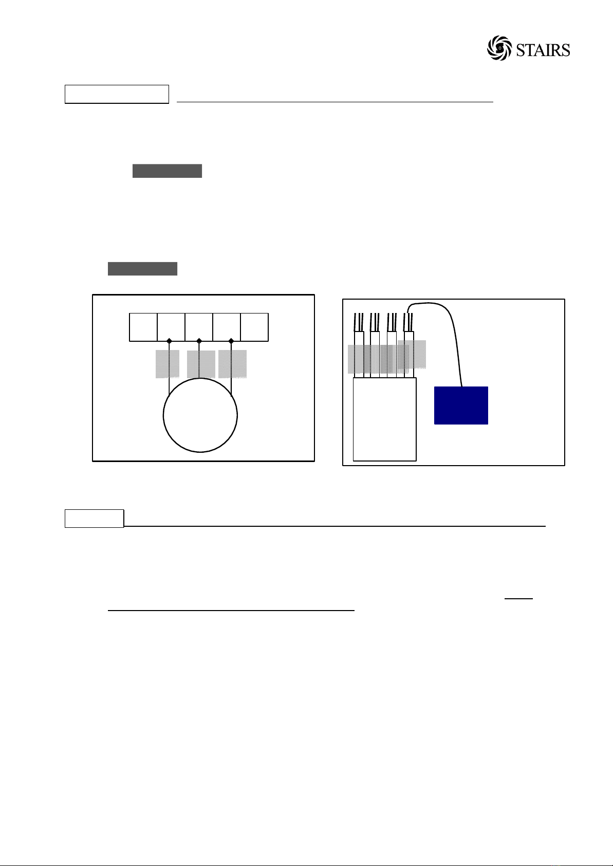
: Non-automatic pumps,
have an automatic operating system
bump operating water level near the
minimum operating level as the automatic
cut-off switch incorporated inside the
motor will be activated. To avoid dry
operation, install an automatic operating
system, as shown in Fig-1 and maintain a
safe operating water level.
(7) For automatic pumps, install the floats as
shown in Fig-2.The pump may not start
if a floats switch touches the wall of the
water tank or the piping. Install the floats
so that this will not happen.
H1: Lowest water level (Motor flange)
H2: Operating water level
This must be above the top of the motor
Op
e
ra
t
i
ng
Water
Le
ve
l
S
t
op
Water Level
Fig-2