Stairville D1210 User manual
Owner‘s Manual
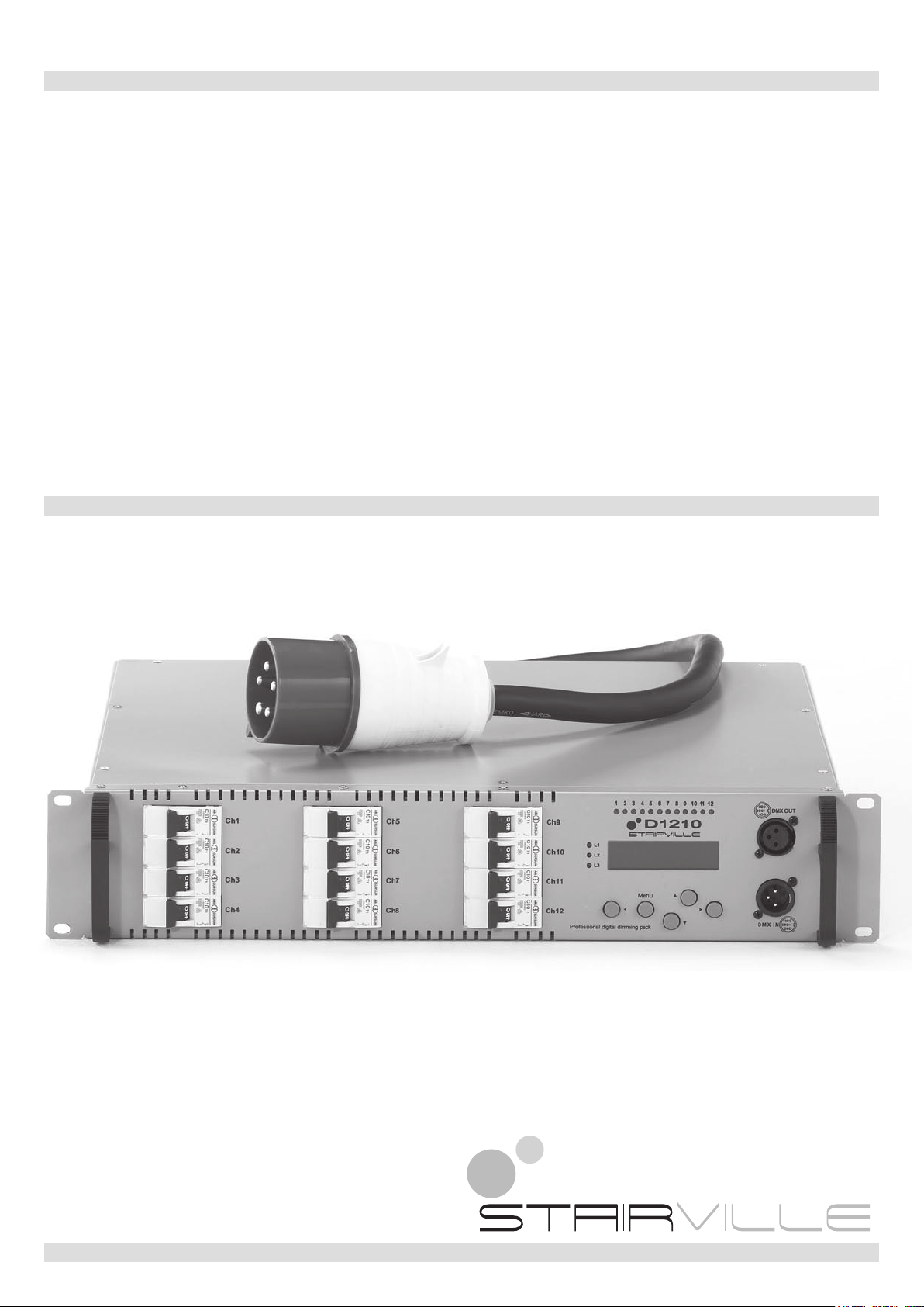
12 CHANNEL DIGITAL
DIMMER PACK
D1210

2
Notes on safety
For your own safety you must read through this chapter at rst completely!
Risk of electrical shocks!
Only connect the device to a mains power supply, that complies to the technical specications •
given in this manual.
Do not operate the device if the power cord or the mains plug are damaged.•
Never submerse the device in water. Wipe it with a slightly moistened cloth only.•
Do not expose the device to rain and never use it in a damp or wet environment. Indoor use•
only! Make sure that the power cord never becomes wet or moist during use.
Under no circumstances may you open the device housing. Should you do so your safety would•
not be assured and the warranty will become void. There are no operational components what-
soever inside, only really high voltage that can give you a deadly shock!
Do not place objects containing uids, e.g. ower vases or beer bottles, on or near the device.•
Notice regarding disconnection from mains-power:•
To completely disconnect the device from mains power, you must pull the plug from the power
socket. For this reason the device should be placed in a position where unobstructed access to
the power socket is assured at all times, so that in an emergency you will be able to immediately
pull out the plug. To eliminate the risk of re you have to completely disconnect the power plug
from the power socket when the device is not going to be used.
Always grasp the power cord by the plug. Do not pull on the cord itself and never touch the pow-•
er cord with wet hands as this could result in a short circuit or an electrical shock. Do not place
the device, speakers or anything else on the power cord and make sure that it does not become
clamped. Never tie knots in the power cord and do not bind it together with other cables. Lay the
power cord so that no one can step on or stumble over it. A damaged power cord can cause a
re or an electrical shock. Check the power cord from time to time. Should it become damaged
contact our customer service department to have it replaced.
Always operate the device only on a properly wired and correctly earthed socket (see specica-•
tions), never sever the power cord’s earth wire. Otherwise a LIFE THREATENING situation ex-
ists!
Never use this device in places, where it is subject to•
> excessive vibrations and/or impacts,
> temperatures above 30°C / 100°F or below 5°C / 40°F,
> extreme low or high humidity (ideal humidity is between 35% and 80%).
Riskofre!
Never leave the device unattended during operation.•
Never cover the ventilation slots of the device while it is on. Do not place the device in locations•
that are subject to direct sunlight. If you do, it may overheat and become irreparably damaged.
Never operate the dimmer pack in the vicinity of heat sources such as cookers, heating ele-•
ments or other heat producing installations.
Do not place open re sources, such as candles, on the device.•
Before a storm and/or a thunderstorm with a risk of lightning, disconnect the device from the•
electrical power source.
Risk of personal injury!
Keep children away from the power cord and the device. Children frequently underestimate the •
dangers of electrical devices.
Provide a stable location for the device.•
Do not operate the device if it has sustained a fall or is damaged. Have the device checked or,•
if necessary, repaired by qualied technicians.
3
ATTENTION!
Damages caused by the disregard of this user manual are not subject to warranty. Neither the•
manufacturer nor the importer will accept liability for these kind of damages or any resulting
damages, defects, or problems. The electric connection must only be carried out by a qualied
electrician! All electric and mechanical connections must comply with European safety norms.
Specifications
AC INPUT....................230V AC, 50-60Hz, 1, 2 or 3 phases, max. 32A / phase
LOAD...........................12 channels, max. 10A / channel
Output connector.........2 x Harting 16-pin
DMX Signal..................DMX 512 / 1990
DMX connectors..........input......XLR 5-pin male
.....................................output ...XLR 5-pin female
Dimension:...................19” 2U, 483 (L) x 90 (H) x 410 (D) mm
Weight .........................14.9 kg
Our products are subject to a process of continual further development. Therefore modications to
the technical features remain subject to change without further notice.
Disposal
Never throw the device into the regular household waste at the end of its useful life.
This product is subject to the European Directive 2002/96/EC.
Dispose of the device through an approved disposal centre or at your community waste•
facility.
Observe the current existing regulations. In case of doubt contact your disposal facility.•
The packaging is certied via a dual system. Take all packaging materials to an environ-•
mentally friendly disposal facility in compliance with the local regulations.
Maintenance and care
Never submerse the device in water or any other liquid. Don‘t let any liquid get into the housing. •
This would damage the unit and cause a short circuit.
Before cleaning the device you must disconnect it from the mains. Clean the surface of the •
device only with a slightly damp cloth. Never use petrol, solvents or any aggressive cleaners!
These could damage the surface of the unit‘s housing!
Features
Digital signal interface DMX512 (1990)X
Each channel have it’s own DMX addressX
Individual preheat on every channel (0-15%)X
Individual control curve on every channel (Switch/Linear/Sqrt)X
Adjustable voltage limit for every channelX
Auto frequency tracking 45-65 HzX
Test modeX
LCD displayX
Internal temperature displaying for each Phase moduleX
Variable fan speed corresponding to internal temperature for each phase moduleX
Overheat protection for each phase moduleX

4
Front panel
q Circuit Breaker tDMX Signal output
wPhase LED indicator yDMX Signal input
e Channel LED indicator u Control Keys
r LCD Display
Rear panel
i AC Power Output
o Cooling Fan
a Main AC Power Input
5
Installation / Power up
Plug the 12 lamps into the Harting sockets (i) as is shown on the back panel. Insert the DMX
cable in the corresponding Inputs (y). Unwrap the power cord (a) and plug into a 3x230V socket
capable of delivering 32A per phase. D1210 have three sections (phases) named L1, L2, L3.
They can be powered in several modes:
each section powered by its individual phase;•
one section powered by one phase and the other two powered by another phase;•
all sections powered by a single phase.•
Note!
It is recommended to power up all three phases (do not leave any dimmer section unpowered even
if you don’t use it).
Once you have powered the unit the phase indicator LED’s will light and the LCD will display after
a second: “STAIRVILLE D1210 / DIGITAL DIMMER”. This means that D1210 is ready to be used.
The green LED’s on the front panel will show the intensity for channels.
Turn on the Circuit Breakers (q) for the channels you want to use and the lamps will light up.
Note!
It is recommended to set up the unit (see next pages) before you turn on the Circuit Breakers (q).
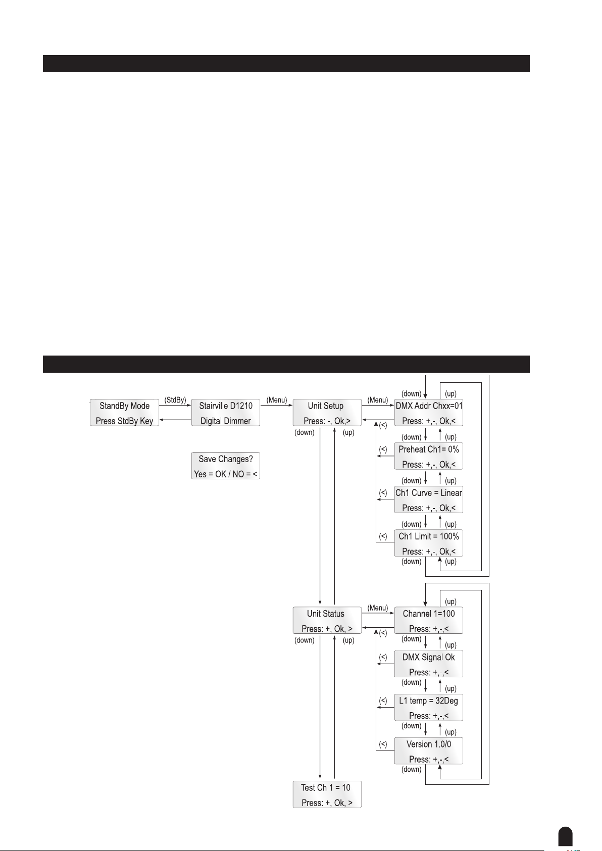
Unit Setup

6
Preheat setup
D1210 have individual channel preheat values which can be set in this way:
Enter “Unit Setup”->”Preheat Ch1= 0” and press (Menu) key.
The channel number will start to blink. Select the desired channel pressing (Up) / (Down) keys
and then press (>). Remember that you can toggle between channel no and channel value using
(<) and (>) keys. The preheat value for selected channel will blink. Change the settings by press-
ing (Up) / (Down) keys. If you want to change another channel preheat value press (<) key and
change the channel number. When you have set all preheats to desired values, press (Menu) and
the “Save Changes?” view will appear on LCD. To save changes press (Menu) key, to quit without
saving the changes press (<) key.
Note!
The max preheat value is 50, and in the on/off mode the preheat is shut off.
DMX Address setup
D1210 have individual channel DMX addresses. To set these addresses enter “Unit Setup”->”Ch
1 DMX Addr= 01” and press (Menu) key. The channel number will start to blink. Select the desired
channel by pressing (Up) / (Down) keys and then press (>). Change the settings pressing (Up) /
(Down) keys. If you want to change another channel address value press (<) key and change the
channel number. Press (Menu) key and the “Save Changes” view will appear on LCD. To save
changes press (Menu) key, to quit without saving the changes press (<) key.
Note!
Changing the DMX address for Ch1 will modify all addresses. If you want to modify the address for
each channel rst set Ch1 address and after that set the others addresses!
Control curve setup
D1210 have 5 control curves for each channel:
Linear / Sqrt / Curve1 (dimmer mode)•
On/off (switch mode) - The channel will be on (full) when its value passes over 64. And the chan-•
nel will be turned off when its value drops below 32.
Note!
The individual channel settings must be set before turning on the circuit breaker. Some non-dim-
ming lamps may be damaged if they are used in dimmer mode.
To select the control curve enter Unit Setup->Ch Curve and press (Menu) key. The channel number
will start to blink. Select the desired channel by pressing (Up) / (Down) keys and then press (>),
the curve for selected channel will blink. Change the settings by pressing (Up) / (Down) keys. If
you want to change another channel preheat value, press (<) key and change the channel number.
When you have set all channel curves, press (Menu) and the “Save Changes?” view will appear on
LCD. To save changes press (Menu) key, to quit without saving the changes, press (<) key.
Test mode
You can test channels (set individual channel value) using Test Mode.
Enter “Test Ch 1= 0” and press (Menu) key. The channel number will start to blink. Select the de-
sired channel by pressing (Up) / (Down) keys and then press (>). Remember that you can toggle
between channel no and channel value using (<) and (>) keys. The channel value will start to blink.
Change the settings by pressing (Up) / (Down) keys. If you want to change another channel value,
press (<) key and change the channel number.
7
When you want to exit, press (Menu) and the “Save Changes?” view will appear on LCD. To save
changes press (Menu) key, to quit without saving the changes press (<) key.
Limiter setup
D1210 have individual voltage channel limit values for prolonging bulb life. This can be set in this
way:
Enter “Unit Setup”->”Limit Ch1=255” and press (Menu) key.
The channel number will start to blink. Select the desired channel pressing (Up) / (Down) keys and
then press (>). Remember that you can toggle between channel no and channel value using (<)
and (>) keys. The Limiter value for selected channel will blink. Change the settings by pressing
(Up) / (Down) keys. If you want to change another channel limiter value, press (<) key and change
the channel number. When you have set all limits to desired values, press (Menu) and the “Save
Changes?” view will appear on LCD. To save changes press (Menu) key, to quit without saving the
changes press (<) key.
Note!
The minimum limiter value is 200 and in the on/off mode the limiter is shut off.
Unit Status
Display channels values
You can see the value of each channel of the D1210 entering “Unit Status”-> “Channel 1= 68” and
press (Menu) key. The channel number will start to blink. To change the current channel press (Up)
or (Down) keys. To leave this menu press (Menu).
DMX status
You can check DMX status entering “Unit Status”->”DMX Signal”
If the DMX reception is OK the LCD will display “DMX signal OK”. If there’s something wrong with
DMX signal the LCD will display “No DMX signal”.
Note!
Changing the status of DMX reception will be displayed by blinking for 3 seconds (e.g. when you
turn on /off the DMX console).
Displaying unit temperature
You can view the D1210 internal temperature for each phase module entering “Unit Status”->”Unit
Temp=34Deg”. When the temperature exceeds 45° the corresponding cooling fan will start. The
fan speed will increase with internal temperature until 65°, when the fan speed will be max. If the
temperature of any of the 3 modules reach 95°, then the D1210 enters overheat protection until
the temperature for that module drops below 80°. In this situation the channels corresponding to
the overheated module will be shut down and the LCD will display blinking “L..... Overheat / Unit
Overheated”.
Note!
To avoid overheating do not cover the cooling fans and ensure adequate ventilation!

© 2010
Musikhaus Thomann
Treppendorf 30 • 96138 Burgebrach • Germany
www.thomann.de
Table of contents
Other Stairville Dimmer manuals


Popular Dimmer manuals by other brands


City Theatrical
City Theatrical QolorFLEX 5809 quick start guide

LiteGear
LiteGear LiteDimmer Spectrum AC600 user guide

Lutron Electronics
Lutron Electronics MRFA-3LD-URC quick start guide

SkyLink
SkyLink WR-001 user manual

Ekinex
Ekinex KNX 90-230 Setup and installation guide

movie-intercom
movie-intercom RC4 quick start guide