Ekinex KNX 90-230 Operating and safety instructions

1
KNX 90-230 Vac 4-channel phase cut dim-
mers
Code: EK-GD1-TP-4-HV
Datasheet STEKGD1TP4HV_EN
TP1
SNote: values for output current and nominal power
have to be intended as maximum values, depen-
ding on the ventilation conditions. The reported va-
lues are measured with a room temperature of 40
°C. For electronic loads and/or LEDs whose PFC or
harmonic distortion is not known, consider the maxi-
mum power halved compared to the nominal value.
i
REFLEKGD1TP4HV
KNX bus device with 4-channel phase-cut dimmer fun-
ction for lighting loads, with power supply voltage 90 - 230
Vac at 50/60 Hz. Use in KNX standard home and building
automation systems.
Description
The ekinex KNX phase-cut dimmer powered at 90-230
Vac with 4 channels EK-GD1-TP-4-HV allows the bright-
ness control of luminous loads with supply voltage 90 -
230 Vac at 50/60 Hz. The device has a maximum output
power of 200 W for each channel. The loads that can be
used with the dimmer can be: incandescent lamps, mains
voltage halogen lamps, dimmable mains voltage LED
lamps, dimmable mains voltage LED strips, switching
power supplies for dimmable phase cut LEDs. The dim-
mer cuts the phase in Trailing Edge mode (on the falling
edge). The device has an integrated KNX certied bus
communication module with SELV 30 Vdc voltage.
• Channels settable via ETS as independent, in parallel
or with copy function from another channel
• Status indication of the outputs through LEDs
• Block function, forced operation, staircase light, scena-
rios, night, counter and logic functions for each chan-
nel, settable by ETS
• Alarm for short circuit, open load and power failure
• Auxiliary output function with status advice via KNX
• Manual command via membrane buttons and for local
ON/OFF test of channels 1-2-3-4, also in case of KNX
bus absence. A button short press activates/deactiva-
tes the load, pressing it for at least 2 seconds causes
the load to ash approximately every 1 s
Technical data
Inputs
• Power supply: 90 - 230 Vac 50/60 Hz
• Maximum input current: 4 A
Outputs
• Power supply: 90 - 230 Vac 50/60 Hz
• Output power per channel 110 W @ 110 Vac, 220 W @
220 Vac, 230 W @ 230 Vac
• Minimum load power: 1 W per channel
• Maximum output current: 1 A per channel
Dimming
• Trailing edge dimming mode with open load control
(OPEN CIRCUIT) and short circuit on the load (SHORT
CIRCUIT)
• Dimming range: 1-100%
Environmental conditions and other characteristics
• Operating temperature: - 20 ° C ... + 40 ° C
• Storage temperature: - 40 ° C ... + 60 ° C
• Transport temperature: - 40 ° C ... + 60 ° C
• Maximum case temperature (tc): 80 °C
• Relative humidity: 91% non-condensing
• Protection degree: IP00 (IP20 inside a wall-mounting
box or electrical panel)
• Loads and supply wiring: 1.5 mm2solid – 2.5 mm2
stranded (16 - 13 AWG)
• KNX bus wiring: 0.26 ÷ 0.5 mm2 – 23 ÷ 20 AWG
• Stripping: 5.0 - 6.0 mm
• Housing in plastic material
• Device suitable for installation in panels/cabinets 4 UM
• Weight 200 g
• Dimensions (LxHxW): 71x91x62 mm
Main functional characteristics
• ON/OFF control and regulation of the luminous intensi-
ty of single or group lighting xtures
• Fade time on and o, minimum and maximum bright-
ness level, linear or logarithmic regulation curve setta-
ble via ETS
• Soft or instant on and o, with settable delay
• Conguration of behavior after power recovery, bus
ON/OFF, download via ETS
Protections
• OVP Input voltage peak protection
• RVP Overcurrent protection with 3 A non-resettable
fuse
• OCP Output open circuit protection

2
The terminal diagram for power supply and loads is as
follows.
Setup and installation
The steps to setup the device are as follows:
1. Connect the loads to the AC OUT ( -x, N) terminals
of the device
2. Connect the KNX bus to the corresponding terminal of
the device
3. Connect the 90 - 230 Vac power supply to the AC IN (L,
N) terminals of the device
Control, signaling and connection elements
The device is equipped with a spring clamp for connec-
ting the output loads on 4 channels and the 90 - 230 Vac
input power supply (1). There is also a signaling LED for
the presence of the power supply (2), a button and LED
for each channel (3), for local on / o test in case of KNX
bus absence, a terminal for connecting the KNX bus (4),
a KNX programming button (6) with LED (5).
To carry out the local on/o test, briey pressing the but-
ton turns the connected load on or o, while pressing it
for at least 2 seconds makes the load ash approximately
every 1 s.
Montaggio
The devices have degree of protection IP00 (IP20 inside
a wall-mounting box or electrical panel).and are therefore
suitable for use in dry interior rooms.
Before removing the device, make sure that inputs, ou-
tputs, and the AC power supply have been disconnected.
When assembling, make sure to leave only the front pa-
nel accessible; all other sides must not be accessible. For
the mounting proceed as follows:
• with the aid of a tool bring the locking device in the fully
lowered position (a);
• place the upper edge of the rear inner prole on the
upper edge of the rail (b);
• rotate the device towards the rail (c);
• push the locking device upward until it stops (d).
Nr. Label Connection
1 - Power supply and loads clamps
2 Power Signalling LED
3 x LED and channel x (x = 1,2,3,4) button
4 - KNX bus terminal
5 - Programming LED
6 - KNX Programming button
EK-GD1-TP-4-HV
1
4
Power
1 2 34
EK-GD1-TP-4-HV
Dimmer KNX 90-230V~ 50/60 Hz
Out: 4x 200W
2
3
5
6
1 2 3 45678 9 10 11 12
N
NL L
1
COM
2
COM
3
COM
COM
4
Label Connection
L AC input - Live
N AC input - Neutral
COM Channel x (x=1,2,3,4) AC output - Neutral
Channel x (x=1,2,3,4) AC output - Live
x
a b
dc
Before removing the device, be sure that inputs, outputs,
and the input power supply have been disconnected. Use
a screwdriver to slide down the locking device and remo-
ve the device from the rail.
Note. When mounting the device in boards and ca-
binets it shall be provided the necessary ventilation
so that the temperature can be kept within the ope-
rating range of the device.
i

3
KNX bus line connection
The connection to the bus network takes place via the
KNX terminal included in the delivery and inserted in the
special housing located on the front of the device in the
upper part.
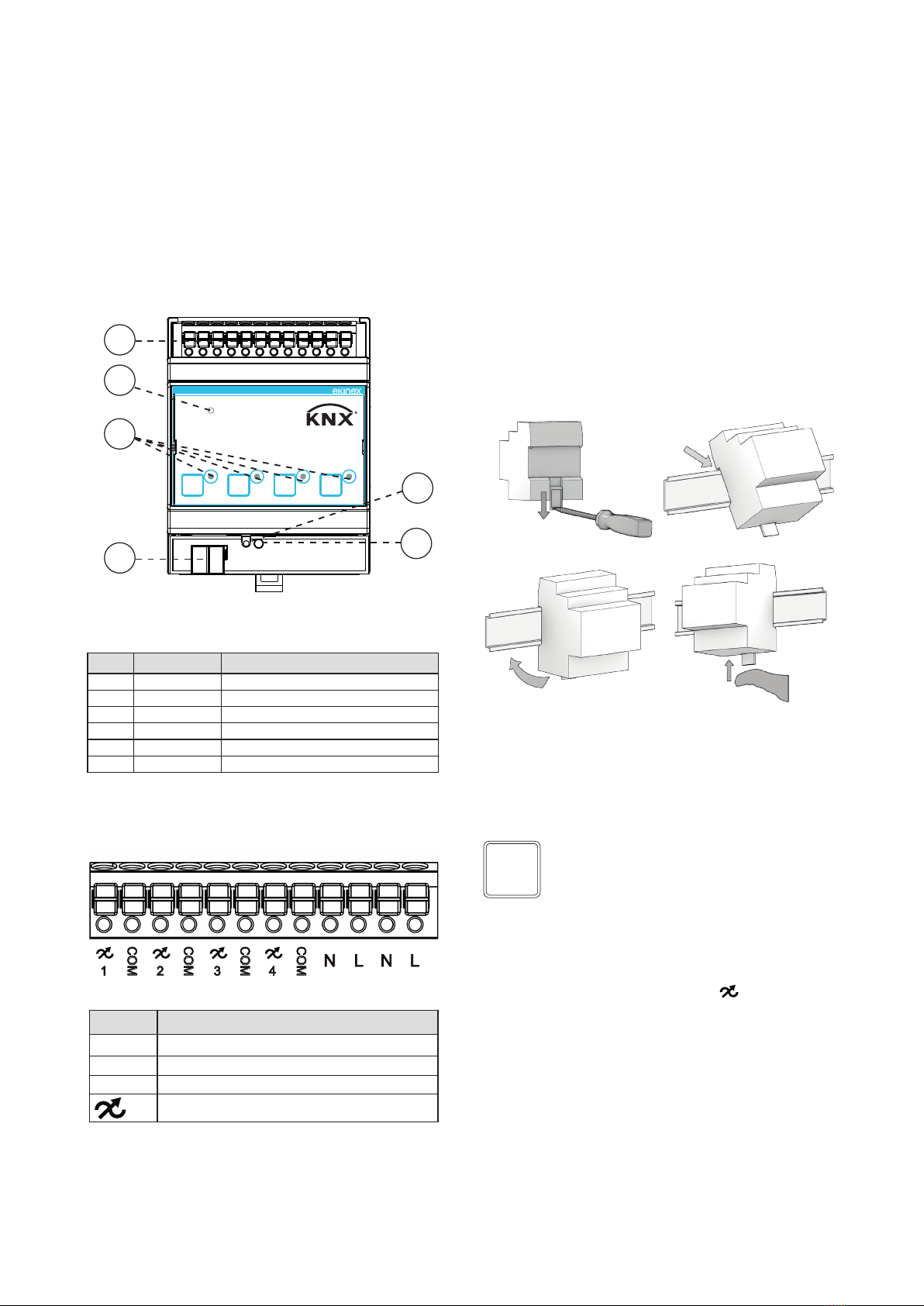
Characteristics of the KNX terminal block
• spring clamping of conductors
• 4 seats for conductors for each polarity
• terminal suitable for KNX bus cable with single-wire
conductors and diameter between 0.6 and 0.8 mm
• recommended wire stripping approx. 5 mm
• color codication: red = + (positive) bus conductor,
black = − (negative) bus conductor
Connection of loads and power supply
The connection to the 90-230 Vac 50-60Hz power supply
is done via the spring terminals located in the lower part
of the device.
Characteristics of the supply and loads terminal block
• Spring tightening of the conductors
• Power and loads wiring: 1.5 mm2solid – 2.5 mm2stran-
ded – 16 - 13 AWG
• Stripping recommended approx.: 5.0 - 6.0 mm
Warning! The electrical connection of the appliance
must be carried out exclusively by qualied person-
nel. Incorrect installation can cause electrocution or
re. Before making the electrical connections, make
sure you have deactivated the mains voltage.
!
Outputs
The cables connected to the outputs must be correctly
sized and must be isolated from any wiring or parts with
dierent voltages. The length and type of connection ca-
bles must comply with the regulations in force.
Conguration and commissioning
The conguration and commissioning of the device re-
quires the use of the ETS® (Engineering Tool Software)
V5 program or later versions. These activities must be
carried out in accordance with the design of the building
automation system created by a qualied professional.
To congure the device parameters, the corresponding
application program or the entire ekinex® product data-
base must be loaded into the ETS® program. For detailed
information on the conguration possibilities, consult the
application manual of the appliance available on the web-
site www.ekinex.com.
!
INSTALLATION TECHNICAL NOTES
• Installation and maintenance must be
performed only if the power supply has
been turned o.
• Installation and maintenance must only
be performed by qualied personnel in
compliance with current regulations.
• The product must be installed inside
a wall mounting box or an electrical pa-
nel, where it is recommended to install a
surge protector.
• The product must be protected by a sui-
tably sized fuse.
• The product must be protected by a su-
itably sized magnetothermic switch on
the main input line.
• The product must be installed in a verti-
cal position with the front / label facing
the front or in a horizontal position with
the front / label facing upwards. Other
product installation positions are not
allowed.
• Do not connect inductive loads.
• Do not connect to UPS (uninter-
ruptible power supply) with ou-
tput other than Pure Sine Wave.
The device is not grounded. Protection
from accidental contacts is guaranteed
by the casing.
• Use in thermally harsh environments
could limit the output power.
• In the system, keep the 90-230Vac circu-
its and the non-SELV circuits separate
from the SELV circuits at very low safety
voltage and from the KNX bus
• It is absolutely forbidden to connect, for
any reason whatsoever, directly or indi-
rectly, the 90-230Vac mains voltage to
the KNX bus or to the loads.
• Use double insulated cables.
Warning! To power the KNX bus lines, use exclusi-
vely KNX bus power supplies (e.g. ekinex EK-AB1-
TP, EK-AG1-TP or EK-AM1-TP). The use of other
power devices can compromise communication
and damage the devices connected to the bus.
!

4
Note. The conguration and commissioning of KNX
devices require specialized skills. To acquire these
skills, you should attend the workshops at KNX cer-
tied training centers.
i
Installation diagrams
The device can be installed by wiring the outputs either
with a separate COM pole or with a common COM pole.
Therefore the following schemes can be created:
1. Outputs with separate COM pole connection
2. Outputs with common COM pole connection
The terminals indicated by the COM label can be used as
a common terminal for the loads.
KNX
bus
90-230 Vac
50-60 Hz
L
N
+
-
Power
1234
EK-GD1-TP-4-HV
Dimmer KNX 90-230V~ 50/60 Hz
Out: 4x 200W
Installation diagram with outputs connected
to the separate COM pole
KNX
bus
90-230 Vac
50-60 Hz
L
N
+
-
Power
1234
EK-GD1-TP-4-HV
Dimmer KNX 90-230V~ 50/60 Hz
Out: 4x 200W
Installation diagram with outputs connected
to the common COM pole
Commissioning
For commissioning the device the following activities are
required:
• make the electrical connections as described above;
• turn on the bus power supply;
• switch the device operation to the programming mode
by pressing the programming pushbutton (5) loca-
ted on the front side of the housing. In this operating
mode, the programming LED is turned on;
• download into the device the physical address and the
conguration with the ETS®program.
At the end of the download the operation of the device
automatically returns to normal mode; in this mode the
programming LED is turned o. Now the bus device is
programmed and ready for use.
Device reset
To reset the device, remove the power from the KNX bus;
then press the programming button and, keeping it pres-
sed, restore power to the KNX bus: if, after approximately
10 s, the programming LED ashes quickly, it means that
the reset has been carried out. At this point it is necessary
to re-address and congure the device via ETS.
Warning! The input N terminals must never be con-
nected to the COM outputs.
!
Warning! In conguration 2, the internal fuse on
the load, which implements overcurrent protection,
does not trip.
The electronic short circuit protection remains fun-
ctional.
!
Warning! The reset operation brings back the devi-
ce to its factory delivery state. The addressing and
value of the parameters set during conguration are
lost.
!

5
Summary table of load types depending on the input power supply
TE = Trailing Edge
@220 V 50/60 Hz
SYMBOL LOAD TYPE
MAX POWER
MODE CURVE
SINGLE
CHANNEL
SUM OF
CHANNELS
Halogen or incandescent bulbs (230V ~ 50/60Hz) 230 W 460 W TE Linear
Ferromagnetic transformers (Halogen bulbs at 12/24V
~ 50/60Hz) Incompatible
Electronic transformers (Halogen bulbs 12/24V ~
50/60Hz) 115 W 330 W TE Logarithmic
Dimmable LED lamps (230V ~ 50/60Hz) 115 W 330 W TE Logarithmic
Lamp power supplies LED (230V ~ 50/60Hz) 115 W 330 W TE Logarithmic
LED strip (230V ~ 50/60Hz) 230 W 460 W TE Linear /
logarithmic
Energy saving lamps (ESL/CFL) Incompatible
Warning! Never connect the transformer wi-
thout rst having connected the load on the se-
condary, to avoid overvoltages that are destruc-
tive to the appliance.
!
@110 V 50/60 Hz
SYMBOL LOAD TYPE
MAX POWER
MODE CURVE
SINGLE
CHANNEL
SUM OF
CHANNELS
Halogen or incandescent bulbs (230V ~ 50/60Hz) 110 W 220 W TE Linear
Ferromagnetic transformers (Halogen bulbs at 12/24V
~ 50/60Hz) Incompatible
Electronic transformers (Halogen bulbs 12/24V ~
50/60Hz) 55 W 110 W TE Logarithmic
Dimmable LED lamps (230V ~ 50/60Hz) 55 W 110 W TE Logarithmic
Lamp power supplies LED (230V ~ 50/60Hz) 55 W 110 W TE Logarithmic
LED strip (230V ~ 50/60Hz) 110 W 220 W TE Linear /
logarithmic
Energy saving lamps (ESL/CFL) Incompatible

6
Product
code
Application program
(## = release)
Communica-
tion objects
(nr. max)
Group ad-
dresses
(nr. max)
EK-GD1-TP-4-HV
APEKGDXTPXHV##.knxprod
102 102
Maintenance
The device is maintenance-free. To clean use a dry cloth.
It must be avoided the use of solvents or other aggressive
substances.
Dimensions [mm]
71 62
45
91
71 62
45
91
Marks
• KNX
• CE: the device complies with the Electromagnetic
Compatibility Directive (2014/30/EU), the Low Volta-
ge Directive (2014/35/EU) and the RoHS 2 Directive
(2011/65/EU).
• Reference Standards: EN 63044-5-1:2019, EN 63044-
5-2:2019, EN 63044-3:2017, EN 62368-1:2020.
Disposal
At the end of its useful life the product
described in this datasheet is classied
as waste from electronic equipment in
accordance with the European Directive
2012/19/EU (WEEE recast), and cannot
be disposed together with the municipal
undierentiated solid waste.
Document
This technical datasheet refers to the A1.0 release of the
ekinex® device code. EK-GD1-TP-4-HV and is available
for download on the website www.ekinex.com in PDF for-
mat (Portable Data Format).
Warning! Incorrect disposal of this product may
cause serious damage to the environment and
human health. Please be informed about the
correct disposal procedures for waste collec-
ting and processing provided by local authori-
ties.
!
Warnings
• Installation, electrical connection, conguration and
commissioning of the device can only be carried out by
qualied personnel in compliance with the applicable
technical standards and laws of the respective countri-
es
• Opening the housing of the device causes the imme-
diate end of the warranty period
• In case of tampering, the compliance with the essential
requirements of the applicable directives, for which the
device has been certied, is no longer guaranteed
• ekinex®KNX defective devices must be returned to the
manufacturer at the following address: EKINEX S.p.A.
Via Novara 37, I-28010 Vaprio d’Agogna (NO) Italy
Other information
• This datasheet is aimed at installers, system integra-
tors and planners
• For further information on the product, please contact
the ekinex®technical support at the e-mail address:
com
• Each ekinex®device has a unique serial number on
the label. The serial number can be used by installers
or system integrators for documentation purposes and
has to be added in each communication addressed to
the EKINEX technical support in case of malfunctioning
of the device
• KNX®and ETS®are registered trademarks of KNX As-
sociation cvba, Brussels
© EKINEX S.p.A. The company reserves the right to make changes to this
documentation without notice.
This manual suits for next models
1
Table of contents
Other Ekinex Dimmer manuals

Ekinex
Ekinex EK-GD1-DL-4-HV User manual

Ekinex
Ekinex EK-GA1-TP Instructions for use

Ekinex
Ekinex EK-GD2-TP-1-HV User manual

Ekinex
Ekinex EK-GD2-TP-1-HV Instructions for use

Ekinex
Ekinex EK-GL1-DL User manual

Ekinex
Ekinex EK-GM2-DL User manual

Ekinex
Ekinex EK-GO1-DL User manual

Ekinex
Ekinex EK-GH1-DL User manual