StandDesk Ergo Tech STANDING DESK User manual
800 524 2744
STANDING DESK
Installation Instructions
P516373 REV B
PAGE 1 OF 17

800 524 2744
IMPORTANT SAFETY INSTRUCTIONS
SAVE THESE INSTRUCTIONS
When using an electrical furnishing, basic precautions should always be followed,
including the following:
Read all instructions before installing or using the furnishing.
CONSIGNES DE SECURITE IMPORTANTES
VEUILLEZ GARDER CES CONSIGNES
Lorsque vous utilisez des meubles electriques, des precautions de base doivent toujours
etre respectees, y compris les suivantes.
Veuillez lire attentivement ces consignes avant d’installer ou d’utiliser le meuble.
WARNING
• Review the assembly instructions to confirm that the appropriate critical components and
accessories are being used with the furnishing.
• Failure to follow instructions can result in product damage, personal injury or both.
• All electrical connections must be fully engaged and locked. Loose connections can cause fire and/or
electrical shock.
• If there is visible damage on the product it must not be installed.
• Do not overload the product as this can result in product damage, personal injury or both.
• Electric height adjustable tables are not designed for continuous operation. Do not exceed the
maximum duty cycle (10% - 2 min. on, 18 min. off) or product damage could occur.
• Risk of electric shock and product damage. Do not open the control box, power supply or columns on
electric height adjustable tables.
• Risk of electrical shock. Always unplug this furnishing from the electrical outlet before cleaning
or servicing.
• Risk of electrical shock, personal injury and product damage. Close supervision is necessary
when this furnishing is used by, or near children, invalids, or disabled persons.
• Sitting or standing on this furniture may cause personal injury and product damage.
• Risk of personal injury and product damage, use this furnishing only for its intended use as described
in these instructions. Do not use attachments not recommended by the manufacturer.
• Risk of personal injury and product damage. Height adjustable tables require a minimum of 1" clearance
between the worksurface and adjacent objects on all sides.
ELECTRICAL RATING: 120V, 1.8A, 50/60 HZ
WORKSURFACE LOADING (MAXIMUM USER LOAD): 150 LBS.
AVERTISSEMENT
• Veuillez lire les instructions de montage afin de vous assurer que les composants critiques et
accessoires appropriés sont utilisés avec le mobilier.
• Ne pas suivre ces instructions peut entrainer des dommages sur le produit, des blessures, or les deux.
• Toutes les connexions électriques doivent etre completement enfoncées et verrouillées. Des
connexions desserrées peuvent provoquer un incendie et/ou des chocs électriques.
• S’il ya des dommages visibles sur le produit, ii ne doit pas être installé.
• Ne surchargez pas le produit car cela peut entrainer des dommages sur le produit, des blessures, ou les deux.
• Les bureaux électriques réglables en hauteur ne sont pas conçus pour un fonctionnement continu.
Ne pas dépasser le cycle de service maximal (10% - 2 minutes allumes, 18 minutes éteints) ou des
dommages au produit pourraient se produire.
• Risque de décharge électrique, et d'endommagement du produit. Ne pas ouvrir le boîtier de contrôle,
le boîtier d’alimentation, ou les colonnes sur les bureaux réglables en hauteur.
• Risque d’électrocution. Veuillez toujours débrancher le mobilier de la prise électrique avant le
nettoyage ou l’entretien.
• Risque de décharge électrique, de blessures, et d’endommagement du produit. Une surveillance
étroite doit être exercée lorsque le systeme d’ameublement est utilisé par, ou pres d’enfants, des
personnes invalides ou des personnes handicapées.
• Se tenir debout ou assis sur le meuble peut entrainer des dommages sur le produit et des blessures.
• Risque de blessures et d’endommagement du produit; veuillez utiliser cet systeme d’ameublement
uniquement aux fins décrites dans ces instructions. N’utilisez pas des accessoires qui ne sont pas
recommandés par le fabricant .
• Risque de blessures et d’endommagement du produit. Les bureaux électriques réglables en hauteur nécessitent
un dégagement minimum de 1 pouce entre la surface du travail et des objets adjacents sur tous les côtés.
SPECIFICATIONS ELECTRIQUE: 120V, 1.8A, 50/60 HZ
CHARGEMENT DE SURFACE DE TRAVAIL (CHARGE MAXIMUM DE L’UTILSATEUR): 68 KG
PAGE 2 OF 17

800 524 2744
STANDING DESK
Parts List
A Primary Leg 1x
Black = 65020610-1
White = 65020604-1
Silver = 65020630-1
B Secondary Leg 1x
Black = 65020610-2
White = 65020604-2
Silver = 65020630-2
C Side Bracket 2x
Black = R033 41310
White = R033 41304
Silver = R033 41330
D Side Bar 2x
Black = R033 41510
White = R033 41504
Silver = R033 41530
E Center Bracket 2x
Black = R033 41410
White = R033 41404
Silver = R033 41430
F Center Lid 1x
Black = R033 41610
White = R033 41604
Silver = R033 41630
G Feet 2x
Black = R063 39110
White = R063 39104
Silver = R063 39130
H ø 4.8 x 16mm Flat Head Wood Screw 26x
R011 51x
I ø 4 x 16mm Pan Head Wood Screw 2x
R011500
J M8 x 16mm Flat Head Bolt 4x
R011086
K Glider 4x
RM-175
L Velcro Strip 4x
R010250
M Cable Clip 2x
R010206
N Switch Bracket 1x
RM-405-3
O Power Supply 1x
R013 339
P Switch 1x
R013345-2
Q Power Cable 3.5m 1x
R013 345-9
R DC Cable 1x
R013 344
S Motor Cable 1x
067200
T Hex Key 5mm 1x
R011905
1.8m
2m
3.5m
PAGE 3 OF 17
800 524 2744
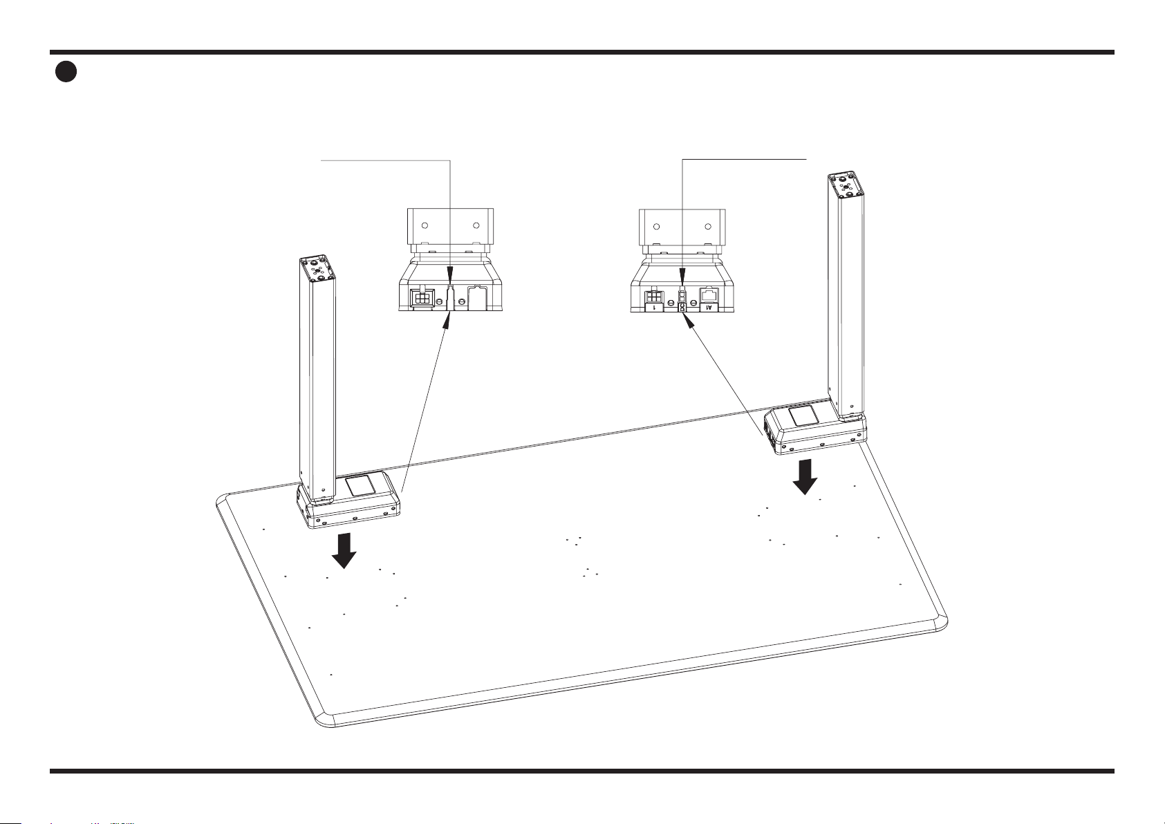
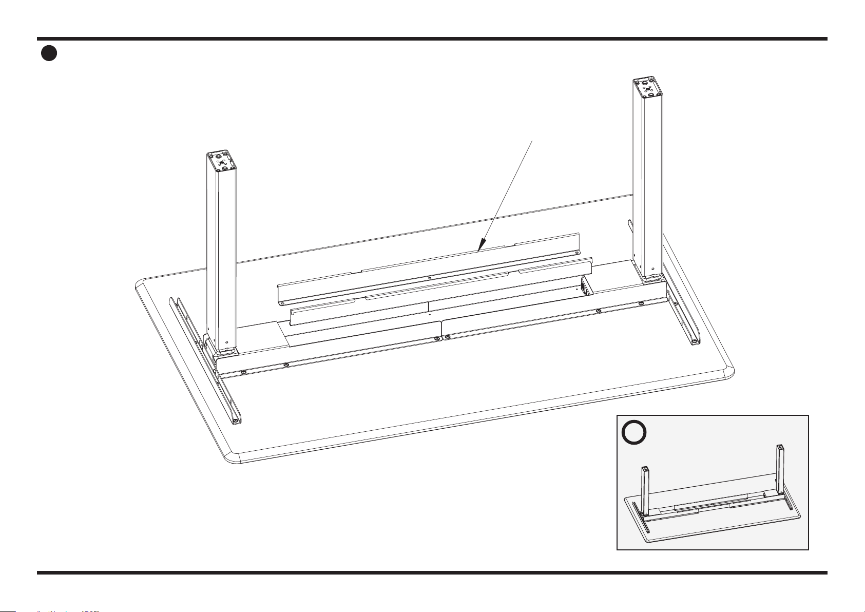
1
Secondary Leg
connection view
Primary Leg
connection view
B
(1x)
A
(1x)
PLACE PRIMARY AND SECONDARY LEGS
Place the Primary and Secondary
Legs (Part A & Part B) on the bottom
of your worksurface.
PAGE 4 OF 17
800 524 2744
Image shown with 48" x 30" surface
2
Image shown with 60" x 30" surface
i
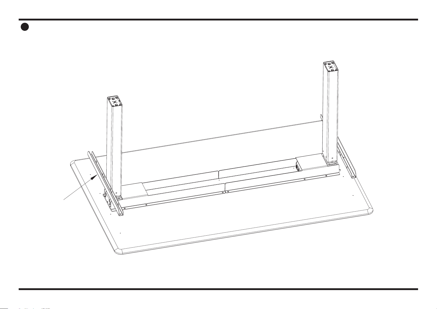
C
(2x)
PLACE & ALIGN SIDE BRACKETS
Place and align Side Brackets
(Part C) onto the worksurface.
PAGE 5 OF 17
800 524 2744
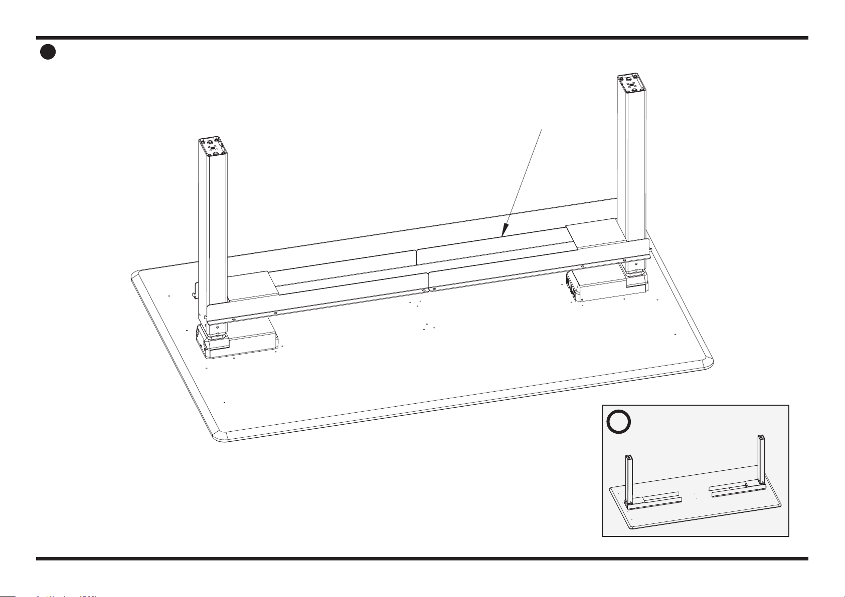
3
D
(2x)
PLACE & ALIGN SIDE BARS
Place and align the Side Bars (Part D)
onto the Legs using the hinges
and slots.
PAGE 6 OF 17
800 524 2744
Image shown with 48" x 30" surface
E
(2x)
4
Image shown with 60" x 30" surface
i
PLACE & ALIGN CENTER BRACKETS
Place and align Center Brackets
(Part E) on top of the Side Brackets
(Part C) to connect them.
PAGE 7 OF 17
800 524 2744
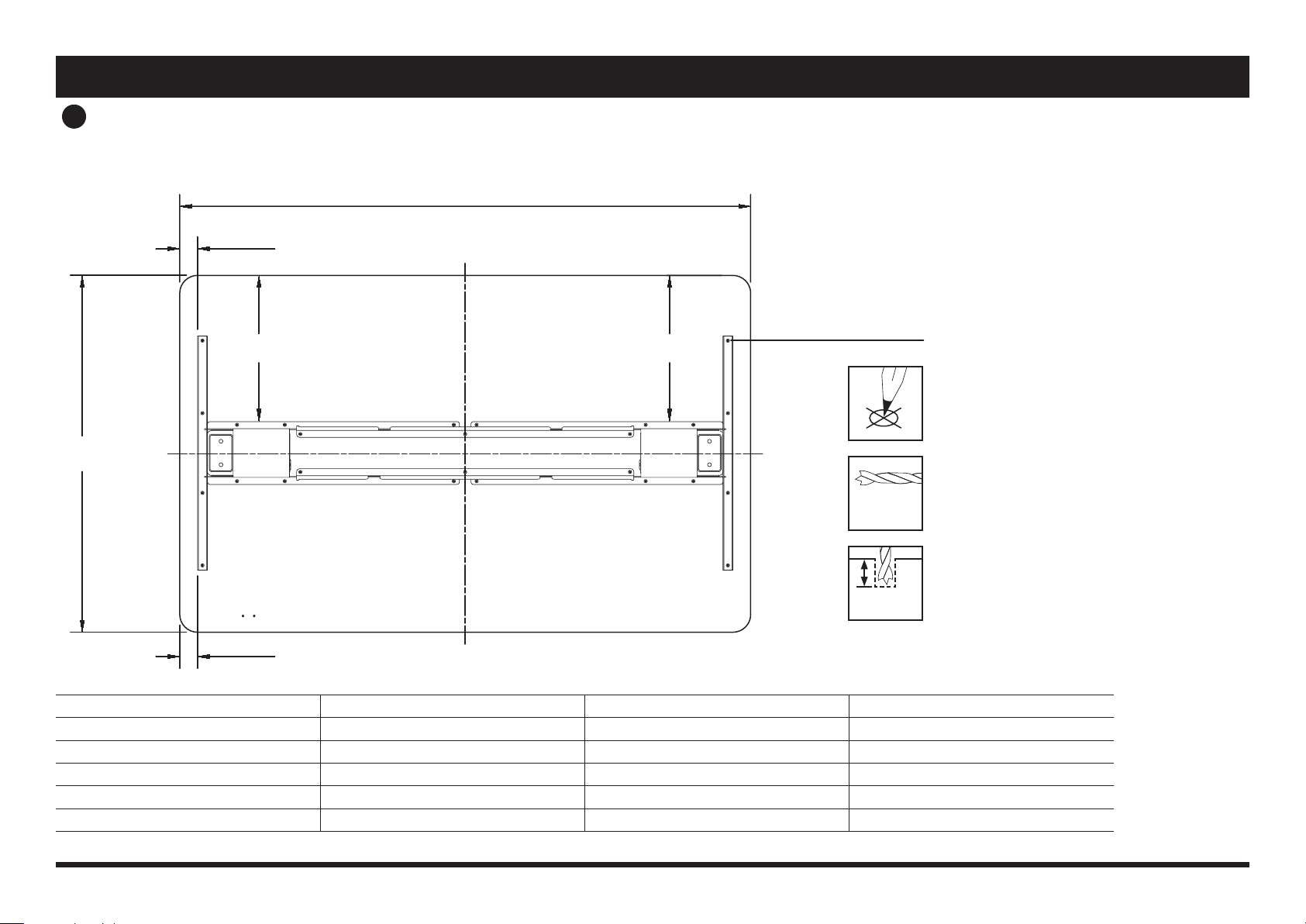
FRAME ALIGNMENT DIAGRAM
L
L1
L1
W1 W1
W
L W L1 W1
48in - 72in (1219.2mm - 1828.8mm) 30in (762.0mm) 1.5in (38.1mm) 12.25in (311.2mm)
48in - 72in (1219.2mm - 1828.8mm) 27in (685.8mm) 1.5in (38.1mm) 10.75in (273.1mm)
48in - 72in (1219.2mm - 1828.8mm) 26in (660.4mm) 1.5in (38.1mm) 10.25in (260.4mm)
48in - 72in (1219.2mm - 1828.8mm) 24in (609.6mm) 1.5in (38.1mm) 9.25in (235.0mm)
45in (1143.0mm) 24in (609.6mm) 0.5in (12.7mm) 9.25in (235.0mm)
PILOT HOLES
Mark pilot hole locations
Recommended drill bit size for
pre-drilling pilot holes:
1/8" (3mm) diameter wood drill bit
Recommended pilot hole drill depth:
1/4" (6mm)
Rectangular: (45in, 48in - 72in) Long x (24in, 26in, 27in, 30in) Wide
ø 1/8"
(3mm)
1/4"
(6mm)
5
IF WORKSURFACE HAS PREDRILLED PILOT HOLES SKIP TO NEXT STEP
PAGE 8 OF 17
800 524 2744
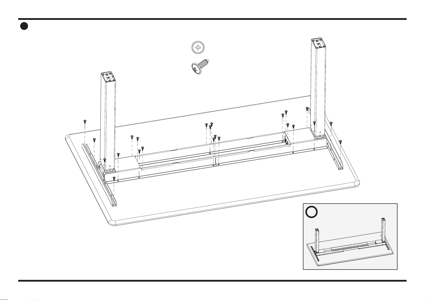
6WOOD SCREW ATTACHMENT
Install the components placed on
the worksurface from the previous
steps to the worksurface using
26 wood screws (Part H).
Image shown with 60" x 30" surface
i
H
(26x)
PAGE 9 OF 17
800 524 2744
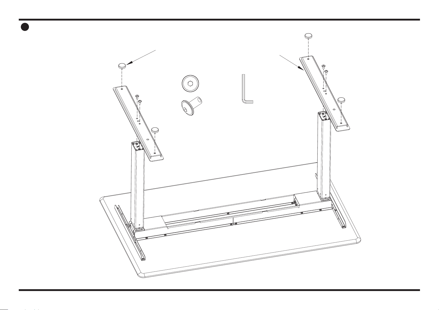
7
K
(4x)
J
(4x)
T
G
(2x)
INSTALL FEET AND GLIDERS
Place Feet (Part G) on top of Legs
so that the Leg ts into the top side
of the Feet.
Secure Feet to Leg using 4 bolts (Part J)
and supplied Allen wrench (Part T).
Screw in Gliders (Part K) to be hand
tight. You can later adjust and level
your desk by screwing/unscrewing
these pads as needed.
PAGE 10 OF 17
800 524 2744
B A
8
I
(2x)
P
N
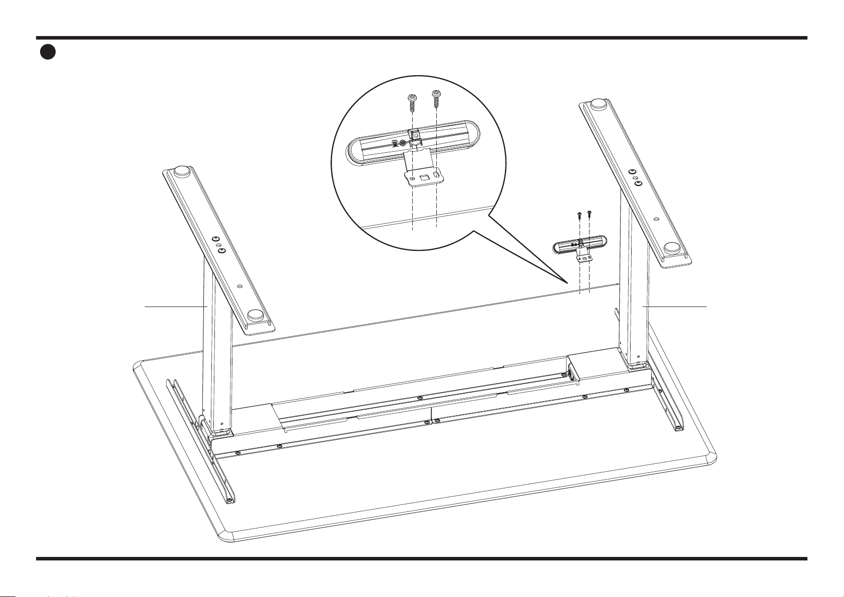
INSTALL SWITCH MOUNT & SWITCH
Align the Switch Bracket (Part N) with the two predrilled
holes near the edge of the worksurface.
Install the Switch Bracket using 2 wood screws (Part I)
to secure the Switch Bracket to the worksurface.
Once bracket is mounted, slide the Switch (Part P)
on the bracket, rmly push it down towards the
worksurface until it’s secure.
PAGE 11 OF 17

800 524 2744
9
P
O
S
QR
NOTE: ONLY APPLY POWER WHEN ALL CONNECTIONS ARE DONE
PLUG IN POWER & SWITCH COMPONENTS
Begin by plugging the Switch (Part P) into the Secondary Leg.
Plug Motor Cable (Part S) into the Primary Leg.
Plug DC Cable (Part R) into the Secondary Leg Actuator and the Power Supply (Part O).
Use the Velcro Strips (Part L) to secure and manage cords neatly if desired.
Ensure enough power cord (Part Q) is available to reach your work space’s plug or outlet.
PAGE 12 OF 17

800 524 2744
10
B
F
A
INSTALL CENTER LID
Place the Center Lid (Part F) on top of the
Center Brackets (Part D) and push down
rmly until it clicks or snaps into place.
To remove the tray, pull up on the
Center Tray Cover until it pops o.
PAGE 13 OF 17

800 524 2744
11 FLIP THE STANDING DESK UPRIGHT
We recommend using two people to
safely flip the completed standing
desk onto its feet.
Check to ensure the power cord
reaches a power source. If not,
remove Center Lid (Part F), pull
more power cord out and re-install
Center Lid.
Plug in the Standing Desk and
ensure Switch is working correctly.
For detailed Switch instructions,
please see page 14-15.
PAGE 14 OF 17

800 524 2744
DIGITAL SWITCH OPERATIONPERFORM INITIAL RESET
Connect power cord to 120v power outlet.
INITIALIZE
The desk cannot drive up if it has not been initialized.
This is error code E01.
How to initialize:
1. Press down key and drive to the lowest position.
Hold the key until the desk stops completely.
2. Reactivate the down key and hold the key until the
desk stops completely. Now the desk can drive up.
/\ = PARALLEL UP
\/ = PARALLEL DOWN
S = STORE MEMORY
• = MEMORY 1
•• = MEMORY 2
••• = MEMORY 3
UP AND DOWN ( \/ /\ )
Just activate either the up or down button for parallel drive
and the system will drive until the button is released again
or the system reaches end position.
MEMORY
The four small buttons are used for memory drive/storing
memory.
STORE MEMORY
• Press S – button, the display will ash for 2 seconds
• Within these two seconds press one of the small buttons
with dots and the position will be stored at this button.
• The panel will acknowledge by showing “1”, “2” or “3” in
the display depending on chosen position
MEMORY DRIVE (small buttons with dots)
Press one of the memory buttons and the system will start
driving to the pre-programmed memory position.
DISPLAY FUNCTION
Shows the actual height in either cm or inch.
ADJUSTING INITIAL HEIGHT
It may be necessary to adjust the displayed height due to
dierent thicknesses of desktops etc. The DPF1C will as
standard either show 68 cm or 24.5 inch as the default
desk height.
PROCEDURE
Press /\ and \/ keys at the same time and keep them pressed
for 5 seconds. This allows the initial height to be adjusted.
Until the initial height can be adjusted, the display will
show three minuses (---) hereafter the display will revert
to showing the height. The height can then be adjusted by
either /\ or \/ until til desired height has been reached. The
system will return to normal operation (and give a short
blink) after 5 seconds of inactivity on the keys.
The feature can be disabled via conguration in which
case pressing the /\ and \/ keys at the same time will be
considered an illegal keypress.
PAGE 15 OF 17

800 524 2744
TROUBLE SHOOTING AND DIAGNOSIS
The included electric height adjustable table that is not
working properly can be evaluated to determine why the
table isn’t functioning.
Take note of how the table is malfunctioning and any error
codes that are displayed on the digital readout switch.
Make sure to check all cables and power cord connections.
Unplug everything (all control cables from control box and
legs, power cord, and control switch from control box),
allow the table to sit for 10 seconds, and then reattach
all connections. While reattaching all connections, check
female ports to ensure all “six” pins in each port are straight
and not bent.
RESET THE WORKSTATION
1. Press the down button and hold until the desk is
fully lowered.
2. Press the down button and release, then immediately
press and hold the down button for 5-6 seconds looking
for slight movement down and then back up. Reset is
complete.
3. Press the up button and desk will function normally.
Reset may need to be performed up to three times in
succession before positive movement is seen.
COLLISION DETECTION
Collision Detection is designed to mitigate hardware
damage if a hard collision between the table and another
surface is to occur. This is done by detecting a predened
dierence in current consumption by the channels on the
control box. If this takes place, the legs are brought to a
halt and run in the reverse direction for about 50mm (1.97")
without having to hit the switch, to avoid any damage to the
components of the table.
FORCE REQUIRED TO ACTIVATE ANTI-COLLISION
Upwards: 44 lbs (20 kg)
Downwards: 88 lbs (40 kg + load on desk and desk itself)
Note: Force required to activate is based on a sudden
concentrated load directly to the leg actuator. Leg position,
amount of surface cantilever, size of application,
and amount of overall loading will aect the sensitivity
and amount of force required to activate.
SITUATIONS IN WHICH ANTI-COLLISION
DOES NOT WORK
• If the collision happens when initializing the table.
• If the collision happens within 1 second of activation, or
after the control box has been released.
• If the collision happens between the oor and the table
and the load on the desk + the weight of the legs are
lower than 40kg.
• If the collision happens for an extended period of time,
like colliding with a soft object.
STANDARD ERROR CODES
ERROR DESCRIPTION ACTION
EOl
Desk has an unknown
position and needs to
be reset
Reset Desk
E23 Channel 1 is detected
missing
Check all cable
connections associated
with port 1
E24 Channel 2 is detected
missing
Check all cable
connections associated
with port 2
E25 Channel 3 is detected
missing
Check all cable
connections associated
with port 3
E59 Safety limit switch
activated on channel 1
Check for obstruction,
or binding due to
frame assembly
E60 Safety limit switch
activated on channel 2
Check for obstruction,
or binding due to
frame assembly
E61 Safety limit switch
activated on channel 3
Check for obstruction,
or binding due to
frame assembly
800 524 2744
?
PAGE 16 OF 17

800 524 2744
SPECIFICATIONS
BASE
• Complete 2-leg, 3-stage, electric light, adjustable frame
• 700mm (27.56") T-foot, centered, entry level construction
• 500mm (19.69") under-frame
• Flex Frame, three-piece, adjustable construction
• Complete frame outside dimension, adjustment range:
44.0" - 70.0" (1168.4mm - 1778.0mm)
- Infinitely adjustable within adjustment range
• Digital programmable control switch with readout,
3x preset, auto-drive
• Finish – Powder coated steel
• Height Range: 21.1" - 47.6" (535.9mm~1209.0mm)
(without desktop)
• Operation: Electric
• Weight Capacity: 220lbs (100kg)
(frame only, without desktop)
• Adjustment Speed: 1.5" (38.0mm)/second
WORKSURFACE / DESKTOP SIZE RANGE
Dimensions:
• Width: 45.0" - 72.0" (1143.0mm - 1828.8mm)
• Depth: 28.0" - 30.0" (711.2mm - 762.0mm)
• Thickness: Minimum 0.71" (18.0mm)
USAGE
• Two parallel drive leg actuators with 1x primary
(DL6000XNM665518), 1x secondary (DL6000XNS665518),
and 1x AC to DC universal power supply (SMPS006)
• Duty cycle: 10% ~ 6 min. Per hour or 2 min.
Use at full load.
• Ambient temperature: +50°F to 104°F (+10°C to 40°C)
• Storage and transportation temperature: 14°F to 158°F
(-10°C to +70°C)
PAGE 17 OF 17
Table of contents
Other StandDesk Indoor Furnishing manuals


Popular Indoor Furnishing manuals by other brands

KIDSMILL
KIDSMILL 60s Series user manual

FMD Furniture
FMD Furniture HALLO 2 210-002 Assembly instructions

Dorel Home Products
Dorel Home Products 4374439N manual

Furniture of America
Furniture of America CM3498PBN Assembly instructions
Arrow
Arrow 3531 Assembly instructions

Rauch
Rauch 29056.4520 Assembly instructions


HULALA HOME
HULALA HOME HRCXA0265 quick start guide

Whittier Wood Furniture
Whittier Wood Furniture McKenzie Media Center Assembly instructions

Teknion
Teknion interpret WWCBSD Installation guides

Habitat
Habitat KITT-SR-AW19-A Assembly instructions

Lightolier
Lightolier Brisa FP28LEC specification

WorkSimpli
WorkSimpli PL 468-30-AI quick start guide