Stanley DUBUIS BPP060F User manual

BPP060F
OUTIL DE SERTISSAGE SANS MATRICES
DIELESS CRIMPING TOOL
DUBUIS
17-19 rue Jules Berthonneau - Z.I. de Villebarou
CS73406 - 41034 BLOIS Cedex - France
0122- BPP060F
MANUEL D’UTILISATION
Sécurité, Utilisation et Entretien
USER MANUAL
Safety, Operation and Maintenance

2 ► BPP060F User Manual
EC DECLARATION OF CONFORMITY
DÉCLARATION DE CONFORMITÉ CE
EC DECLARATION OF CONFORMITY
DÉCLARATION CE DE CONFORMITÉ
EG KONFORMITATSERKLARUNG
DECLARATION CE DE CONFORMIDAD
DICHIARAZIONE CE DI CONFORMITA
150420 ind.E
The undersigned, representing the following manufacturer:
Le soussigné, représentant le fabricant ci-après :
Der Unterzeichner, der den folgenden Hersteller vertritt:
El abajo firmante, en representación del siguiente fabricante:
Il sottoscritto, che rappresenta il seguente produttore
DUBUIS S.A.S. 17-19, rue Jules Berthonneau CS 73406 41034 BLOIS CEDEX - France
Hereby declare that the equipment specified hereunder:
Déclare que l’équipement visé ci-dessous :
Bestätige hiermit, dass erklären Produkt genannten Werk oder Gerät:
Por la presente declaro que el equipo se especifica a continuación:
Dichiaro che le apparecchiature specificate di seguito:
Category: HYDRAULIC CRIMPING TOOLS WITH 18V RECHARGEABLE BATTERY
Catégorie : PRESSES HYDRAULIQUE DE SERTISSAGE SUR BATTERIE 18V
Kategorie: ELEKTROHYDRAULISCHES PRESSWERKZEUG BATTERIEBETRIEBENES 18V
Categoría: HERRAMIENTA HIDRÁULICA DE CRIMPADO A BATERÍA 18V
Categoria: PRESSA IDRAULICA A BATTERIA 18V
Type/Type/Type/Tipo/Tipo: BPP050FC - BPP050OC - BPP060FC
Serial number of equipment: L-00001 à L-99999
Numéro de série de l’équipement :
Seriennummer des Geräts:
Número de serie del equipo:
Matricola dell’attrezzatura:
Has been manufactured in conformity with:
Est fabriqué conformément aux :
Wurde hergestellt in Übereinstimmung mit:
Ha sido fabricado de acuerdo con:
È stata costruita in conformità con:
Directives / Directives / Richtlinie / Directriz / Direttiva
2006/42/EC, 2014/30/EU, 2011/65/EU
Harmonized Standards / Normes harmonisés / Harmonisierte Standards / Normas armonizadas / Norme armonizzate:
2006/42/EC NF EN ISO 15744 (décembre 2008)
NF EN ISO 3744 (février 2012)
NF EN ISO 20643 (septembre 2008)
NF EN ISO 11201 (décembre 2010)
NF EN 12096 (septembre 1997)
2014/30/EU EN 55014-1 (juin 2017)
EN 55014-2 (juillet 2015)
EN 62233 (septembre 2013)
EN 62311 (octobre 2008)
2011/65/EU NF EN IEC 63000 (décembre 2018)
The undersigned is responsible for compilation of the technical file and makes this declaration on behalf of DUBUIS.
Le soussigné est responsable de la constitution du dossier technique et fait cette déclaration au nom de DUBUIS.
Der Unterzeichner ist für die Zusammenstellung der technischen Unterlagen verantwortlich und gibt diese Erklärung im Namen von DUBUIS ab.
El abajo firmante es responsable de la elaboración del expediente técnico y realiza esta declaración en nombre de DUBUIS.
Il sottoscritto è responsabile della compilazione del dossier tecnico e fa questa dichiarazione a nome di DUBUIS.
Signature
Blois, January 4, 2022
Fait à Blois le 4 janvier 2022
Patrick VERVIER,
Engineering Manager / Responsable Bureau d’études
DUBUIS S.A.S. 17-19, rue Jules Berthonneau CS 73406 41034 BLOIS CEDEX - France

BPP060F User Manual / Manuel d’utilisation ◄ 3
UKCA DECLARATION OF CONFORMITY
150420 ind.E
UKCA DECLARATION OF CONFORMITY
The undersigned, representing the following manufacturer:
Manufacturer:
DUBUIS S.A.S.
17-19, rue Jules Berthonneau
CS 73406
41034 BLOIS CEDEX - France
Declares that the product(s)
Product identification:
Description:
HYDRAULIC CRIMPING TOOLS WITH 18V RECHARGEABLE BATTERY
Model:
BPP050FC - BPP050OC - BPP060FC
Serial number:
L-00001 à L-99999
Conforms to the UK Regulations:
The supply of Machinery (Safety) Regulations 2008, SI 2008/1597 (as amended)
Electromagnetic Compatibility Regulations, 2016, SI 2016/1091 (as amended)
The Restriction of the Use of Certain Hazardous Substances in Electrical and Electronic Equipment Regulations 2012,
SI 2012/3032 (as amended)
Designated Standards:
SI 2008/1597 NF EN ISO 15744 (December 2008)
NF EN ISO 3744 (February 2012)
NF EN ISO 20643 (September 2008)
NF EN ISO 11201 (December 2010)
NF EN 12096 (September 1997)
SI 2016/1091 EN 55014-1 (June 2017)
EN 55014-2 (July 2015)
EN 62233 (September 2013)
EN 62311 (October 2008)
SI 2012/3032 NF EN IEC 63000 (December 2018)
The undersigned is responsible for compilation of the technical file and makes this declaration on behalf of DUBUIS.
Signature
Blois, January 4, 2022
Patrick VERVIER,
Engineering Manager
DUBUIS S.A.S. 17-19, rue Jules Berthonneau CS 73406 41034 BLOIS CEDEX - France

4 ► BPP060F User Manual
WARRANTY
DUBUIS and STANLEY Infrastructure (hereinafter called “Stanley”), subject to the exceptions contained below,
warrants new tools for a period of one year from the shipping date from Stanley, to be free of defects in material and/
or workmanship at the time of de-livery. Stanley will, at its option, repair or replace any tool or part of a tool, or new
part, which is found defective upon examination by a Stanley authorized service outlet or by Stanley’s factories in
Blois, France or Milwaukie, Oregon USA.
HIGH PRESSURE TOOLS: High pressure tools (branded “DUBUIS”) such as cable cutters, crimpers, hydraulic high
pressure pumps, have been designed for NON INTENSIVE use. Warranty is limited to 10.000 cycles on manual tools
and 15.000 cycles for energized tools.
FULL PAYMENT: A Guaranty claim doesn’t not allow to partly or totally defer the payment of the equipment.
WARRANTY CLAIMS: To benet from Stanley warranty, individual has to inform without any delay Stanley about
the defects of the equipment in material and/or workmanship. It is also requested to supply with the warranty claim
documentation which proves the sale/purchase of the tool or the tools’ rst date of usage and serial number. The
term “DOCUMENTATION” as used in this paragraph is dened as a bill of sale, or letter of intent from the rst retail
customer.
RESPONSIBILITY: Equipment users must take all necessary security measures.
EXCEPTIONS FROM WARRANTY
FREIGHT COSTS: Freight costs to return parts to Stanley, if requested by Stanley for the purpose of evaluating a
warranty claim for warranty credit, are covered under this policy if the claimed part or parts are approved for warranty.
Freight costs for any part or parts which are not approved for warranty credit will be the responsibility of the individual.
DIES & CUTTING ACCESSORIES: Dies & cutting accessories such as breaker tool bits, dies, blades … are warranted
to be free of de-fects in material and or workmanship at the time of delivery only.
ITEMS PRODUCED BY OTHER MANUFACTURERS: Components which are not manufactured by Stanley and are
warranted by their respective manufacturers.
Costs incurred to remove a Stanley manufactured component in order to service an item manufactured by other
manufacturers.
REPAIRS, ALTERATIONS, MODIFICATIONS: Alterations or modications to any tool or part. All obligations under this
warranty shall be terminated if the new tool or part is altered or modied in any way.
Any failure or performance deciency attributable to repairs by anyone which in Stanley’s sole judgment caused or
contributed to the failure or deciency.
NORMAL WEAR: Any failure or performance deciency attributable to normal wear and tear such as tool bushings,
retaining pins, wear plates, bumpers, retaining rings and plugs, rubber bushings, recoil springs, seals, guiding rings, …
INCIDENTAL / CONSEQUENTIAL DAMAGES: To the fullest extent permitted by applicable law, in no event will
STANLEY be liable for any incidental, consequential or special damages and/or expenses.
FREIGHT DAMAGE: Damage caused by improper storage or freight handling.
LOSS TIME: Loss of operating time to the user while the tool(s) is out of service.
IMPROPER OPERATION: Any failure or performance deciency attributable to a failure to follow the guidelines and/or
procedures as outlined in the tool’s operation and maintenance manual.
MAINTENANCE: Any failure or performance deciency attributable to not maintaining the tool(s) in good operating
condition as out-lined in the Operation and Maintenance Manual.
HYDRAULIC PRESSURE & FLOW, HEAT, TYPE OF FLUID: Any failure or performance deciency attributable
to excess hydraulic pressure, excess hydraulic back-pressure, excess hydraulic ow, excessive heat, or incorrect
hydraulic uid.
MIS-APPLICATION: Any failure or performance deciency attributable to mis-application. “Mis-application” is dened
as usage of products for which they were not originally intended or usage of products in such a matter which exposes
them to abuse or acci-dent, without rst obtaining the written consent of Stanley. PERMISSION TO APPLY ANY
PRODUCT FOR WHICH IT WAS NOT ORIG-INALLY INTENDED CAN ONLY BE OBTAINED FROM STANLEY
ENGINEERING.

BPP060F User Manual ◄ 5
EC DECLARATION OF CONFORMITY ...........................................................................................................................2
UKCA DECLARATION OF CONFORMITY ......................................................................................................................3
WARRANTY .....................................................................................................................................................................4
SAFETY SYMBOLS .........................................................................................................................................................6
SAFETY PRECAUTIONS.................................................................................................................................................7
TOOL ANATOMY..............................................................................................................................................................8
SPECIFICATIONS & ACCESSORIES..............................................................................................................................9
USING THE TOOL .........................................................................................................................................................10
CRIMP SOFTWARE.......................................................................................................................................................12
TROUBLESHOOTING ...................................................................................................................................................17
SERVICING: This manual contains safety, operation and routine maintenance instructions. DUBUIS recommends that
servicing of hydraulic tools, other than routine maintenance, must be performed by an authorized and certied dealer.
Please read the following warning.
To ll out a product warranty validation form, and for information on your warranty, visit
www.stanleyinfrastructure.com and select the Company tab > Warranty.
Note: The warranty validation record must be submitted to validate the warranty.
SERIOUS INJURY OR DEATH COULD RESULT FROM THE IMPROPER REPAIR OR
SERVICE OF THIS TOOL.
REPAIRS AND / OR SERVICE TO THIS TOOL MUST ONLY BE DONE BY AN AUTHORIZED
AND CERTIFIED DEALER.
For the nearest certied dealer, call DUBUIS at (33) 2.54.52.40.00 and ask for a Sales Department.
TABLE OF CONTENTS

6 ► BPP060F User Manual
SAFETY SYMBOLS
Always observe safety symbols. They are included for your safety and for the protection of the tool.
LOCAL SAFETY REGULATIONS
Enter any local safety regulations here. Keep these instructions in an area accessible to the operator and maintenance
personnel.
Safety symbols and signal words, as shown below, are used to emphasize all operator, maintenance and repair
actions which, if not strictly followed, could result in a life-threatening situation, bodily injury or damage to equipment.
Refer to user manual.
Wear eye protection.
Wear safety footwear.
Wear protective gloves.
This is the safety alert symbol. It is used to alert you to potential personal injury
hazards. Obey all safety messages that follow this symbol to avoid possible
injury or death.
KEEP HANDS CLEAR OF THE MOVING PARTS. Crushing of hands. Do not
slide your ngers in the dies prole. Do not put your ngers in the head of the
hydraulic crimping tool when you slide the dies inside it. Your ngers could be
pinched very severely.
Handle the locking spindle with precaution to avoid being pinched.
DO NOT CRIMP LIVE CABLES
Front lighting greater than 500 lux at 200mm
Put the connector in the head in the correct position
Protected against solid bodies larger than 1mm.
Protected against low-pressure water jets from all directions.
This safety alert and signal word indicates an imminently hazardous situation
which, if not avoided, will result in death or serious injury.
This safety alert and signal word indicates a potentially hazardous situation
which, if not avoided, could result in death or serious injury.
This safety alert and signal word indicates a potentially hazardous situation
which, if not avoided, could result in death or serious injury.
This signal word indicates a potentially hazardous situation which, if not avoided,
may result in property damage.
This signal word indicates a situation which, if not avoided, will result in damage
to the equipment.
This signal word indicates a situation which, if not avoided, may result in damage
to the equipment.
IP44

BPP060F User Manual ◄ 7
SAFETY PRECAUTIONS
Tool operators must comply with precautions given in this
manual and on the stickers attached to the tool.
These precautions are given for your safety. Review them
carefully before operating the tool.
Supervising personnel should develop additional
precautions relating to the specic work area and local
safety regulations. Place the added precautions in the
space provided on page 6.
The BPP060F crimping tool will provide safe and
dependable service if operated in accordance with the
instructions in this manual. Read and understand this
manual and stickers attached to the tool before operation.
Failure could result in injury or tool damage.
• Keep children and bystanders away while operating the
tool. Distractions can cause you to lose control of the tool.
• Do not rush. Keep proper footing and balance at all
times. This provides better control of the power tool in
unexpected situations.
• When not in use, keep tool out of the reach of children
anddo not allow persons unfamiliar with the tool or these
instructions to operate. The tool is dangerous when
operated by inexperienced users.
• Keep the handles and gripping surfaces must dry, clean
and free of oil and grease. Slippery hanldles and gripping
surfaces make it impossible to safely handle and control
the tool in unexpected situations.
• Do not operate the tool unless thoroughly trained or
under the supervision of an instructor. Establish a training
program for all operators to ensure safe operation.
• Always wear safety equipment such as eye protection,
ear protection, head protection and safety shoes at all
times when operating the tool. Use gloves if necessary.
• The operator must be familiar with all prohibited work areas
such as excessive slopes and dangerous terrain conditions.
Ensure that your footing is rm and in balance at all times.
• Do not inspect, clean or replace tool jaw parts while the
battery is connected. Accidental engagement of the tool
can cause serious injury.
• Do not operate a damaged, improperly adjusted or
incompletely assembled tool.
• Never wear loose clothing that can become entangled in
the working parts of the tool.
• Keep all parts of your body away from pinch points. Long
hair or loose clothing can become drawn into the tool.
• To avoid personal injury or equipment damage, all tool
repair, maintenance and service must be performed by
an authorized service center.
• Never use the tool in the vicinity of ammable materials
or gases.
• Do not use the tool or charge the tool battery in an
explosive atmosphere.
• Cutting or severing of body parts is possible if proper
procedures are not followed.
• Do not use the tool, battery or battery charger for purposes
other than what is described in this manual.
• Always keep critical tool markings, such as labels
and warning stickers, legible. Contact DUBUIS for
replacement labels.
• Do not use the tool while under the inuence of drugs or
alcohol.
• Do not use accessories or attachments other than those
recommended by DUBUIS.
BATTERIES
• Only charge batteries with a DUBUIS recommended
battery charger.
• Do not store batteries with metal objects, such as coins,
nails or keys. Fire can result if battery terminals are
shorted.
• Do not charge a damaged battery. Recycle and replace
damaged batteries with batteries recommended by
DUBUIS.
• Do not incinerate or dispose of batteries in the garbage.
Recycle the batteries.
• Do not expose the battery to temperatures over 130°C
(265°F). Batteries may explode at high temperatures.
• Leakage of liquid from the battery may occur under
extreme use or high temperatures. If battery liquid gets
on your skin:
1. Wash quickly with soap and water.
2. If the liquid gets in your eyes, ush your eyes with
clean water for 10 minutes. Seek medical attention
immediately.
• Never open the battery.
BATTERY CHARGER
• Do not use the battery charger if the cord is damaged.
• Do not place the charger, or set items on or near the
charger, in such a way as to block airow to the charger.
• Do not use the charger with an extension cord unless
absolutely necessary. Use a cord with the proper wire
size for its length, as described in Table below.
Length of Cord (Feet)
(meter)
25
7
50
15
100
30
150
45
Wire Size (AWG)
(mm²)
18
0.8
18
0.8
18
0.8
16
1.30
• Do not open the charger or attempt to modify it in any
way.
• Disconnect the charger from power before attempting to
clean it.
• Do not connect the charger to a transformer or engine
generator.
This tool satises with European safety
standards and UK Conformity.
If you want to dispose this product, do not mix
it with general household waste. There is a
separate collection system for used electronic
products in accordance with legislation that
requires proper treatment, recover and recycling.
8 ► BPP060F User Manual
WHAT IS THE BPP060F CRIMPING TOOL?
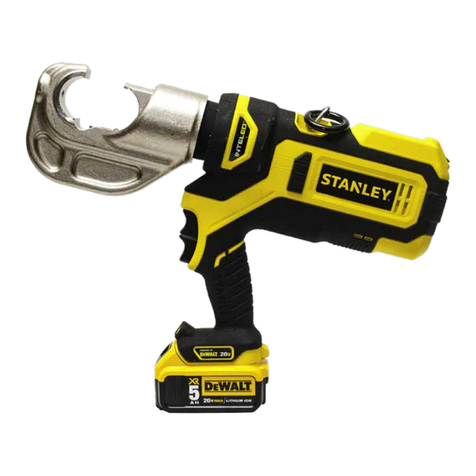
The BPP060F is a battery powered 60kN dieless crimping tool with a ip-top, 4 point head. BPP060F is capable of
crimping copper and aluminum connectors 10 to 400mm² (8AWG to 750Kcmil).
DO NOT put ngers, hands or other body parts inside the
crimping head. Serious injury will result!
DO NOT CRIMP LIVE CABLES
Pressure Release
Trigger
Lifting Ring
USB Port
Battery
Soft Rubber Grip
Crush Hazard Decal
Crimping Jaw
InteLED
Tool Identication &
Warning Decal
Jaw Pin
TOOL ANATOMY
Trigger Lock
Front lighting
Label good/bad
position of
connector

BPP060F User Manual ◄ 9
SPECIFICATIONS
Crimping Force.......................................................................................................................................................... 60kN
Stroke .......................................................................................................................................................................32mm
Battery Type ...................................................................................................................................................... 18V 5.0Ah
Motor ........................................................................................................................................................................... 18V
Tool Length ................................................................................................................445x86x350 (17.5x3.4x13.8 Inches)
Tool Weight (with battery) .....................................................................................................................5,800kg (12.8Lbs.)
Operating temperature range ...........................................................................................-10°C to +60°C (14°F to 140°F)
Estimated Crimps per Battery Charge.................................................................................................................up to 340
Maintenance Interval ................................................................................................................................... 20,000 Cycles
Acoustic power level LwA......................................................................................................................................75dB(A)
The effective weighted acceleration ........................................................................................... does not exceed 2.5m/s²
Crimping Capacity ......................................................................Copper Connectors 10 to 400mm² (8AWG to 750Kcmil)
Crimping Capacity ..................................................................Aluminum Connectors 10 to 300mm² (8AWG to 600Kcmil)
Jaw Type ......................................................................................................................................Flip-top 4 Point, Dieless
ACCESSORIES
18V 5.0Ah Battery ..........................................................................................................................................AB18LI500S
Note: Only use batteries recommended by DUBUIS.
220V AC Charger ............................................................................................................................................. AC18220S
220V AC Charger UK plug........................................................................................................................... AC18220UKS
110V AC Charger US plug.................................................................................................................................AC18110S
12V DC Charger............................................................................................................................................... AC18012S
Note: Only use battery chargers recommended by DUBUIS.
Empty carrying Case ................................................................................................................................................93082
SPECIFICATIONS & ACCESSORIES

10 ► BPP060F User Manual
USING THE TOOL
Set the Trigger Lock BEFORE inserting
or removing dies from the Crimping Head.
USING THE BPP060F
DO NOT CRIMP LIVE CABLES KEEP HANDS CLEAR OF
THE MOVING PARTS
Press and hold the trigger until the die is crimped.
The InteLED ashing green : good crimping.
Press and hold the pressure release until the
return of the piston. Open the crimping jaw.
Trigger
Pressure release
Note: Release the trigger to immediately
stop the tool. Press the pressure release
at any time to open the jaws.
Set the trigger lock.
Release the trigger lock.
Insert battery.
Pull out the jaw pin and open the crimping
jaw. Put the connector with the cable inserted
between the dies. Close the crimping jaw and
lock the jaw pin into place
Jaw Pin
Crimping Jaw
BAD POSITION OF
THE CONNECTOR
GOOD POSITION OF
THE CONNECTOR

BPP060F User Manual ◄ 11
USING THE TOOL
INTELED SYSTEM
The InteLED light ring shows you the status of the crimp in real-time.
White - The tool is crimping. InteLED will stay lit for 30 seconds after the crimp is complete.
Green - The crimping cycle is reached. The crimp is good.
Red - The crimping cycle has been interrupted. Crimp again.
CHECKING BATTERY CHARGE
75 - 100% Charged
51 - 74% Charged
Less than 50% Charged
Charge Battery
Battery Charge Button
CHARGE BATTERY
Battery Charging
Battery Charged
Hot/Cold Delay

12 ► BPP060F User Manual
DUBUIS CRIMP SOFTWARE
DUBUIS Crimp software provides valuable data about each crimp. It is also required to update the tool rmware.
INSTALLATION
1. Download the DUBUIS Crimp software from the STANLEY Infrastructure website.
www.stanleyinfrastructure.com/products/cordless-td
Note: DUBUIS Crimp software requires a minimum of Windows XP SP3 running with administrator rights.
2. Follow the prompts on screen to complete installation.
3. Connect BPP060F to a PC using a micro USB cable.
Note: InteLED will shine blue when connected.
FIRST RUN
1. Run the software using the DUBUIS Crimp software icon on your Windows desktop.
2. You will be prompted to register your software. Left click the “User Registration” button.
3. Fill out the registration form and click “Register”.
Connexion USB
CRIMP SOFTWARE

BPP060F User Manual ◄ 13
USER SELECTION
1. Click the “New User” button
2. Enter the required user information and click “Create”.
3. Select a user and click “OK”.
TOOL INFORMATION
1 2
The Tool Information tab displays important data about the BPP060F.
1. Displays the product type, serial number and rmware version of the tool.
2. Basic data relating to the life and service interval of the tool.
CRIMP SOFTWARE

14 ► BPP060F User Manual
TOOL USAGE DATA
1
2
3
The Tool Usage Data tab displays information about individual tool cycles.
1. Displays the total number of tool cycles, as well as completed and incomplete cycles.
1. The data log shows each cycle, up to 250,000 cycles. Each entry into the log includes;
• Date and time of each crimp
• If the cycle completed successfully
• Amperage and Voltage of the tool during each crimp
• Tool temperature at the end of each crimp
2. Data log sorting lters. Allows you to sort the crimp data in the data log.
WORKSITE REPORTS
1
CRIMP SOFTWARE

BPP060F User Manual ◄ 15
The Worksite Reports tab allows you to group data log entries into a complete tool cycle report.
2
3
4
5
1. Click “Create Report”.
2. Select the date range of the job you are reporting.
3. Select the crimp cycles you want to include in the report.
4. Select a user and a worksite.
Note: If this is the rst time using the software, press the “Worksites” button to create a worksite.
5. Enter notes about the job in the Remarks eld.
6. Click “OK” when nished.
7. Select a report from the reports list.
8. Click “Print Report to PDF” to export the Worksite Report.
7
CRIMP SOFTWARE

16 ► BPP060F User Manual
AVAILABLE UPDATES
The Available Updates tab will allow you to update the tool rmware and update DUBUIS Crimp software.
1. Tool Firmware Update button. When clicked, this will begin to tool rmware update process. Do not unplug the tool
during this process.
2. Software Update button. When clicked, this will update the DUBUIS Crimp software, if an update is available.
1
2
CRIMP SOFTWARE

BPP060F User Manual ◄ 17
TROUBLESHOOTING
Problem Solution
The tool won’t crimp when I press the trigger. Ensure the battery is charged.
Disengage the trigger lock.
The InteLED ashes red when I activate the tool.
At the end of the crimp cycle, Inteled ashes red and then
ashes green for good crimp and then InteLED lights up
white.
The maintenance interval is about to elapse.
Have the tool serviced as soon as possible.
Before the automatic switch off of the tool, InteLED ashes
white during
10 seconds, red during 1 second and the
tool switches off.
The maintenance is achieved.
Have the tool serviced
immediately.
The tool repeatedly give me bad crimps / The InteLED
ashes red after every crimp.
Ensure the battery is fully charged.
Ensure the dies are inserted properly into the crimping
head.
If problem persists, have the tool serviced as soon as
possible.
The tool is leaking hydraulic oil. Have the tool serviced immediately.
The tool is not saving data or will not connect to DUBUIS
Crimp software. Have the tool serviced as soon as possible.

v
4 ► BPP0060F Manuel d’Utilisation
GARANTIE
DUBUIS et STANLEY Infrastructure (ci-après dénommé «Stanley»), sous réserve des exceptions prévues ci-dessous,
garantie les nouveaux outils pour une période d’un an à compter de la date d’expédition de Stanley, qui sont exempts
de défauts en pièces et/ou main-d’œuvre au moment de la livraison. Stanley, à sa discrétion, réparera ou remplacera
tout outil ou toute pièce, ou nouvelle pièce, qui est trouvé défectueuse à l’examen par un centre de service autorisé
par Stanley ou par les usines de Stanley à Blois, en France ou en Milwaukee, Etats-Unis Oregon.
OUTILS À HAUTE PRESSION : les outils haute pression (de marque “DUBUIS”), tels que coupe-câbles, pinces,
pompes hydrauliques à haute pression, ont été créés pour une UTILISATION NON-INTENSIVE. La garantie est limitée
à 10.000 cycles pour les outils manuels et à 15.000 cycles sur les outils électriques.
SOLDE DU PAIEMENT : La demande de prise sous garantie n’autorise pas, ni partiellement ni totalement, de différer
le paiement du matériel.
DEMANDE DE PRISE SOUS GARANTIE : Pour bénécier de la garantie Stanley, la personne est tenue d’informer
sans délai, Stanley sur les défauts de l’équipement en pièces et main d’œuvre. Il est également demandé de fournir,
avec la réclamation, le document qui prouve la vente ou l’achat de l’outil, ou la date de la première utilisation de l’outil
et le numéro de série. Le terme «document», tel qu’utilisé dans le présent paragraphe est déni comme un acte de
vente, ou une lettre d’intention du revendeur.
RESPONSABILITÉ : Il appartient aux utilisateurs du matériel de prendre les mesures de sécurité nécessaires.
EXCEPTIONS DE GARANTIE
FRAIS DE TRANSPORT : Les frais de transport pour renvoyer les pièces à Stanley, si demande effectuée par Stanley
dans le but d’évaluer une demande de garantie, sont couverts par cette garantie si la pièce ou les pièces sont approu-
vées au titre de la prise sous garantie. Les frais de transport pour toute pièce(s) qui ne sont pas approuvées pour le
crédit de garantie seront la responsabi-lité du demandeur.
MATRICES & ACCESSOIRES DE COUPE : Les matrices et les accessoires de coupe tels que les burins, matrices,
formes, les lames... sont garantis d’être exempts de défauts de pièces et/ou main d’œuvre uniquement au moment de
la livraison.
ARTICLES PRODUITS PAR D’AUTRES FABRICANTS : Les composants qui ne sont pas fabriqués par Stanley et qui
sont garantis par leurs fabricants respectifs.
Les frais engagés pour démontrer un composant fabriqué par Stanley en vue de réparer un élément fabriqué par
d’autres fabricants.
RÉPARATIONS, ALTÉRATIONS, MODIFICATIONS : Les altérations ou modications de tout outil ou pièce. Toutes
les obligations en vertu de cette garantie prennent n si le nouvel outil ou la nouvelle pièce est altéré ou modié de
quelque façon. Toute panne ou manque de performance attribuable à la réparation par toute personne qui, dans le
seul jugement de Stanley a causé ou contribué à la panne ou l’insufsance.
USURE NORMALE : Toute panne ou manque de performance attribuable à l’usure normale comme aux bagues,
goupilles, plaques de frottement, pare-chocs, anneaux de retenue et bouchons, bagues de caoutchouc, ressorts,
joints, bagues de guidage...
DOMMAGES ACCESSOIRES DIRECTS/INDIRECTS : Dans toute mesure permise par la loi applicable, en aucun cas
STANLEY ne pourra être tenu responsable des dommages et/ou frais directs, indirects ou spéciques.
DOMMAGES DE TRANSFERT : Les dommages occasionnés par un stockage ou transport inadéquat.
PERTE DE TEMPS : Perte de temps de fonctionnement de l’utilisateur lorsque l’outil(s) est hors service.
MAUVAISE UTILISATON : Toute panne ou manque de performance attribuable au manquement des consignes et/ou
procédures décrites dans le manuel d’utilisation et maintenance de l’outil.
MAINTENANCE : Toute panne ou manque de performance attribuable au manquement du maintien de l’outil(s) en
bon état de fonctionnement tel que décrit dans le manuel d’utilisation et maintenance de l’outil.
PRESSION HYDRAULIQUE & DEBIT, CHALEUR, TYPE DE FLUIDE : Toute panne ou manque de performance attribuable
à une pression hydraulique excessive, d’un débit excessif, une chaleur excessive, ou au uide hydraulique incorrecte.
RÉPARATIONS OU MODIFICATIONS : Toute panne ou manque de performance attribuable à la réparation par toute
personne qui, dans le seul jugement de Stanley a causé ou contribué à la panne ou l’insufsance.
UTILISATON DÉTOURNÉE : Toute panne ou manque de performance attribuable à une mauvaise utilisation. “Utilisation
détournée” est dénie comme l’utilisation des produits d’une manière pour laquelle ils n’étaient pas initialement destinés
ou l’utilisation des produits d’une manière qui les expose à des abus ou accident, sans avoir obtenu au préalable le
consentement écrit de Stanley. L’AUTORISATION D’UTILISER UN PRODUIT POUR LEQUEL IL N’ÉTAIT PAS DES
TINÉ
NE PEUT ÊTRE OBTENUE QUE DE L’INGENIERIE STANLEY.

BPP060F Manuel d’Utilisation ◄ 5
DÉCLARATION DE CONFORMITÉ CE.......................................................................................................................... 2
UKCA DECLARATION OF CONFORMITY ..................................................................................................................... 3
GARANTIE ...................................................................................................................................................................... 4
SYMBOLES DE SÉCURITÉ............................................................................................................................................ 6
CONSIGNES DE SÉCURITÉ.......................................................................................................................................... 7
PRÉSENTATION DE L’OUTIL......................................................................................................................................... 8
CARACTÉRISTIQUES & ACCESSOIRES...................................................................................................................... 9
UTILISATION DE L’OUTIL............................................................................................................................................. 10
LOGICIEL DE SERTISSAGE ....................................................................................................................................... 12
DÉPANNAGE ................................................................................................................................................................ 17
ENTRETIEN : Ce manuel contient des instructions relatives à la sécurité, à l’utilisation et à l’entretien courant de la
machine. Pour l’entretien des outils hydrauliques autre que l’entretien courant, DUBUIS recommande de faire appel à
un revendeur autorisé et certié. Veuillez lire l’avertissement ci-dessous.
Pour remplir le formulaire de validation de la garantie du produit, ou pour plus
d’informations sur votre garantie, rendez-vous à l’adresse
www.stanleyinfrastructure.com et sélectionnez Entreprise > Garantie.
Remarque : Le document de validation de la garantie doit être envoyé à l’adresse
indiquée pour valider la garantie.
UNE RÉPARATION OU UN ENTRETIEN INCORRECT DE CET OUTIL PEUT ENTRAÎNER
DES BLESSURES GRAVES VOIRE MORTELLES.
LES OPÉRATIONS DE RÉPARATION ET/OU D’ENTRETIEN DE CET OUTIL NE DOIVENT
ÊTRE EFFECTUÉES QUE PAR UN REVENDEUR AUTORISÉ ET CERTIFIÉ.
Pour connaître le revendeur agréé le plus proche, appelez la société DUBUIS au (33) 2.54.52.40.00 et demandez le Service Commercial.
TABLE DES MATIÈRES

v
6 ► BPP0060F Manuel d’Utilisation
SYMBOLES DE SÉCURITÉ
Respectez les symboles de sécurité. Ils sont destinés à garantir votre sécurité et à préserver l’outil.
RÉGLEMENTATION LOCALE EN MATIÈRE DE SÉCURITÉ
Saisissez les dispositions réglementaires locales en matière de sécurité dans cet espace. Conservez ces instructions
dans un endroit accessible aux opérateurs et au personnel chargé de la maintenance.
Les symboles de sécurité et les avertissements représentés ci-dessous doivent être respectés rigoureusement car
ils signalent à l’opérateur des activités de maintenance ou de réparation qui présentent des risques de mort ou de
blessures, et de détérioration du matériel.
Consulter le manuel d’utilisation.
Lunettes de protection obligatoires.
Chaussures de sécurité obligatoires
Gants de protection obligatoires.
Ce symbole signale un danger. Il est utilisé pour signaler aux opérateurs la
présence de risques de blessure. Respectez les consignes de sécurité sinalées
par ce symbole pour éviter les risques de blessure ou de mort.
TENIR LES MAINS ÉLOIGNÉES DE LA ZONE EN MOUVEMENT, risque
d’écrasement des mains. Ne glissez pas vos doigts dans le prol de la matrice.
Ne mettez pas vos doigts dans la tête de la presse à sertir lorsque vous faites
glisser la matrice à l’intérieur de celle-ci, vous risqueriez de vous pincer très
fortement les doigts.
Manipulez la tête de l’outil avec précaution pour éviter d’être pincé.
NE PAS SERTIR DES CÂBLES SOUS TENSION
Lampe d’éclairage supérieur à 500 lux à 200mm
Mettre correctement le connecteur à sertir dans la tête
Protégé contre les corps solides supérieurs à 1mm.
Protégé contre les projections d’eau de toutes directions
Ce symbole de danger et ce terme signalent une situation dangereuse immi-
nente qui, si elle n’est pas évitée, entraînera la mort ou des blessures graves.
Ce symbole de danger et ce terme signalent une situation potentiellement dangereuse
qui, si elle n’est pas évitée, risque d’entraîner la mort ou des blessures graves.
Ce symbole de danger et ce terme signalent une situation potentiellement dangereuse
qui, si elle n’est pas évitée, risque d’entraîner la mort ou des blessures graves.
Ce symbole de danger et ce terme signalent une situation potentiellement
dangereuse qui, si elle n’est pas évitée, risque d’entraîner des dégâts matériels.
Ce terme signale une situation qui, si elle n’est pas évitée, entraînera une
détérioration du matériel.
Ce terme signale une situation qui, si elle n’est pas évitée, risque d’entraîner
une détérioration du matériel.
IP44
Table of contents
Languages:
Other Stanley Crimping Tools manuals

Stanley
Stanley DUBUIS KW Hydraulik BPL055 User manual

Stanley
Stanley DUBUIS BPE062 User manual

Stanley
Stanley KW Hydraulik BPE055 User manual

Stanley
Stanley DUBUIS BPE036 User manual

Stanley
Stanley DUBUIS KW Hydraulik BPL031 User manual

Stanley
Stanley DUBUIS KW Hydraulik BPL062 User manual

Stanley
Stanley DUBUIS KW Hydraulik BPE130 User manual

Stanley
Stanley PBD1200 User manual

Stanley
Stanley CT06 User manual

Stanley
Stanley CT04 Guide