Stanley M200 User manual

Fall Management System
M200 Fall Monitor
Setup & User Guide

Copyright Information
All content herein is the property of STANLEY Healthcare, its
Affiliates, or their content suppliers and is protected by United States
and international copyright laws. The compilation of all content is
likewise the exclusive property of STANLEY Healthcare (or the Affiliate
identified in any copyright notice) and is protected by United States
and international copyright laws.
The trademarks, service marks and logos (the ‘Trademarks’) used
and displayed in this publication are registered and unregistered
Trademarks of STANLEY Healthcare, its Affiliates and others. Nothing
herein should be construed as granting, by implication, estoppel or
otherwise, any license or right to use any Trademark displayed herein
without the prior consent of the Trademark owner. STANLEY and
the STANLEY design are two of the trademarks owned by STANLEY
Healthcare and/or its Affiliates (“STANLEY Trademarks”). STANLEY
Trademarks may not be used in connection with any product or service
that is not manufactured by or under license from STANLEY Healthcare
or its appropriate Affiliate.
Important Recommendation
STANLEY Healthcare’s systems are designed to assist staff in providing
a high degree of safety for people and assets and therefore should be
used as a component of a comprehensive safety program of policies,
procedures, and processes. As with every safety system, STANLEY
Healthcare highly recommends regular system operational checks to
verify functional integrity.
There are no known issues with the usage of this equipment in
association with other investigations or treatments at the facility.
Cautions and Warnings
ii M200 Fall Monitor – Setup & User Guide
FAILURE TO HEED THE FOLLOWING CAUTIONS COULD RESULT IN HARM TO YOUR
SYSTEM OR CAUSE IT TO FUNCTION IMPROPERLY, INTERMITTENTLY, OR NOT AT ALL.
• Use the M200 Fall Monitor only with approved accessories.
• Remove batteries when the Monitor is not in use to avoid battery
power loss.
• Use care when connecting the Sensormat® pads. Gently remove or
connect cords using the retaining tab. Pulling on cords may damage
them and/or result in system failure.
CAUTION

M200 Fall Monitor – Setup & User Guide iii
FAILURE TO HEED THE FOLLOWING WARNINGS COULD RESULT IN INJURY TO OR THE
DEATH OF PERSONS IN YOUR CARE.
• A low battery condition in the Monitor is indicated by the Low
Battery indicator flashing YELLOW once every 3 seconds, a Negative
Confirmation Tone, as well as a “Low Battery” voice indication.
Immediately change the monitor’s batteries.
• Test the M200 Fall Monitor and Sensormat pad before each use and
inspect the cords and pads for signs of damage. Immediately replace
any components with signs of wear or damage.
• Sensormats may not be effective with air type bed mattresses or air
type chair cushion pads; test before using.
• Do not place the monitor within 0.3 m (1 ft.) of and facing the
resident. Placing the Monitor on a wheelchair back is acceptable as
long as the monitor is facing away from the resident.
• The M200 Fall Monitor is only one part of your facility’s fall
management program. The M200 Fall Monitor is not a substitute for
proper nursing care or routine visual monitoring by caregivers. The
effectiveness of the M200 Fall Monitor relies entirely on an immediate
response by the caregiver to the M200 Fall Monitor system alarm.
• The M200 Fall Monitor system will not stop a person from leaving a
bed or chair. It is intended only to alert a caregiver that a patient or
resident may need assistance. Other interventions may be required.
• Keep the Sensormat pad flat at all times. Folding the pad may damage
it. Do not use the pad if it has been folded.
• Do not immerse the Sensormat pads in liquids. The pad will not
operate properly if the pad is exposed to excessive liquids. If the pad is
immersed in liquid, discard it immediately.
• Operators of this equipment must be familiar with the functions and
usage as described in this manual, and must be properly trained in the
resident care policies and procedures of the facility.
• Any modification of this equipment is not allowed, voids all
warranties, and may result in injury to or death of persons in your
care.
WARNING
CAUTION
RISK OF EXPLOSION IF BATTERY IS REPLACED BY AN INCORRECT TYPE.
DISPOSE OF USED BATTERIES ACCORDING TO THE INSTRUCTIONS.
ATTENTION
RISQUE D’EXPLOSION SI LA PILE EST REMPLACÉE PAR UN TYPE INCORRECT.
SE DÉBARRASSER DES PILES USAGÉES SELON LES INSTRUCTIONS.

iv M200 Fall Monitor – Setup & User Guide
Contents
CopyrightInformation.................................................................................................... ii
ImportantRecommendation....................................................................................... ii
CautionsandWarnings................................................................................................... ii
Introduction................................................................................................. 1
CheckYourShipment......................................................................................................1
OtherComponentsSoldSeparately..........................................................................1
Overview ...................................................................................................... 2
Hardware Features .................................................................................... 3
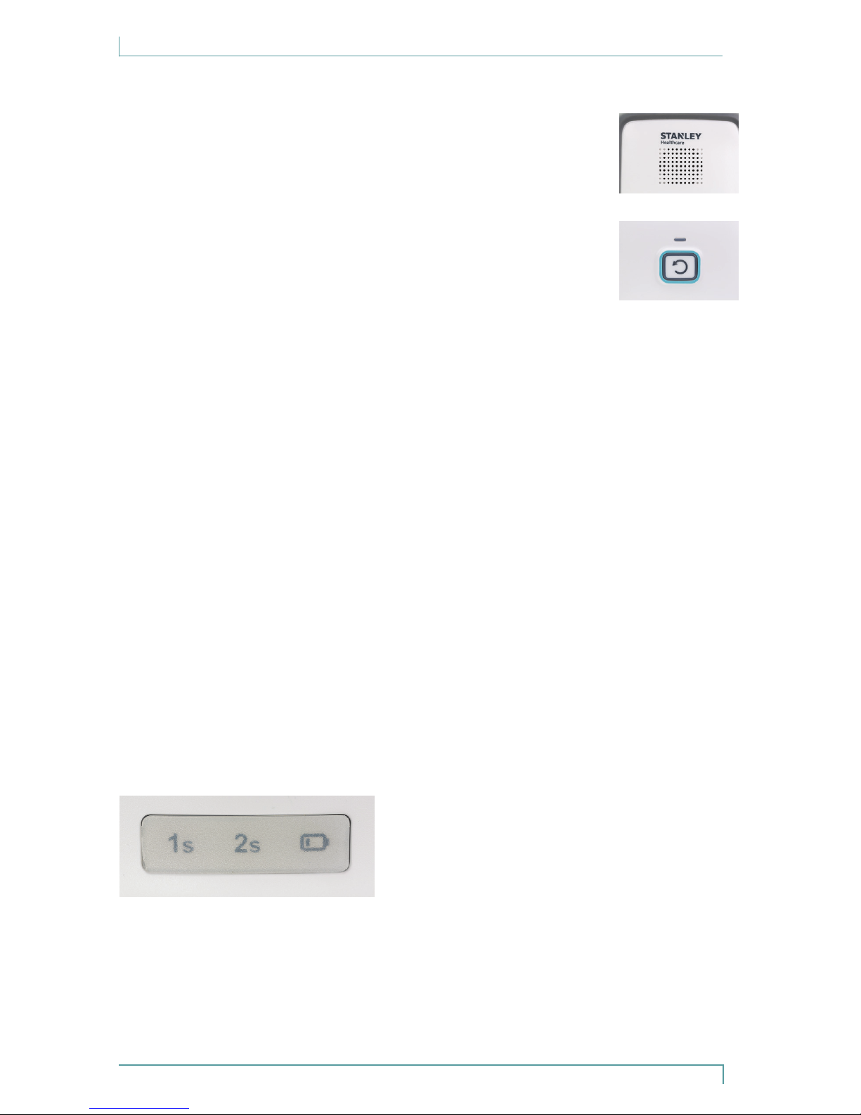
Speaker.................................................................................................................................4
ResetButton.......................................................................................................................4
FrontPanelStatusIndicators........................................................................................4
BatteryCovers....................................................................................................................7
ControlSettings................................................................................................................8
Ports.......................................................................................................................................9
AdditionalFeatures..........................................................................................................9
Alarm and Status Indicators ...................................................................10
ResetButtonRedLED................................................................................................. 10
ResetButtonGreenLED.............................................................................................. 10
ResetButtonAmberLED............................................................................................ 10
StatusIndicatorIcons................................................................................................... 10
Audible Alerts............................................................................................11
PadAlarms....................................................................................................................... 11
ConrmationTones....................................................................................................... 11
LowBatteryBeep........................................................................................................... 11
Monitor Setup ...........................................................................................12
Volume(Speakericon)................................................................................................ 12
ToneSelection(MusicNoteicon)........................................................................... 12
IlluminationIntensity(Lightbulbicon).................................................................. 13
RecordingCustomPadAlarms................................................................................. 14
DIPSwitchSettings....................................................................................................... 15

M200 Fall Monitor – Setup & User Guide v
LatchingandNon-Latching.......................................................................................16
Using Sensormat Pads .............................................................................17
Bed......................................................................................................................................18
Chair/Wheelchair...........................................................................................................18
Toilet...................................................................................................................................18
Seatbelt.............................................................................................................................19
FloorSensormatPad....................................................................................................19
Testing the Sensormat Pads ...................................................................20
Bed,Chair,ToiletandCommode..............................................................................20
Seatbelt.............................................................................................................................21
FloorPad...........................................................................................................................22
Cleaning......................................................................................................22
Using the Monitor.....................................................................................23
HoldMode(30Seconds).............................................................................................23
SuspendMode(2Minutes)........................................................................................24
Batteries......................................................................................................25
ReplacingMonitorBatteries......................................................................................25
Power Supply.............................................................................................26
Monitor Mounting/Installation Options ..............................................27
WallMounting................................................................................................................27
ChairorBedFootboard/HeadboardMounting(Optional).............................29
Interfacing with a Nurse Call System ....................................................30
NurseCall(NC)Alarms.................................................................................................31
Compatibility...................................................................................................................31
Audible Alarms and Tones.......................................................................32
System Specications ..............................................................................33
Regulatory Compliance...........................................................................34
Warranty Information ..............................................................................35

vi M200 Fall Monitor – Setup & User Guide
M200 Fall Monitor Package Contents

Introduction
M200 Fall Monitor – Setup & User Guide 1
Introduction
The STANLEY Healthcare M200 Fall Management System uses a
pressure-sensitive pad to detect the presence of a patient/resident, and
a monitor to notify facility staff in the event of premature departure
from a bed, chair, or toilet seat.
Check Your Shipment
The M200 Fall Monitor package includes:
1 – Monitor with wheelchair clip and built-in bumper
1 – Wall Mount Bracket Kit including 4 anchors and screws,
4 Dual Lock®fasteners (Part# WMB-1000)
1 – Battery Compartment Cover (open-window version)
3 – 3V CR123A Lithium Batteries (not rechargeable)
This document (0980-165-000)
Other Components Sold Separately
Sensormat®pads – available in the following models:
• 14 day (73030 - Chair; 74030 - Bed)
• 30 day (73000, 73010 - Chair; 74000, 74010 - Bed)
• 45 day (93010 - Chair; 92010 - Bed)
• 90 day (73001, 73011 - Chair; 74001, 74011 - Bed)
• 180 day (93020 - Chair; 92020 - Bed)
• 1 year (93030 - Chair; 92030 - Bed)
Toilet Pad (Part# 75000, 75001)
Commode Pad (Part# 75002)
Floor Pad (Part# 93045)
Seatbelt (Part# 0707-945), Seatbelt Extender (Part# 0707-946)
Wall Mount Bracket Kits (Part# WMB-1000)
Bed and Chair Wire Clip (Part# BMB-1000)
Nurse Call Cable (Part# 0707-569) - grey, 8’, ¼“ mono plug
Remote call button (Part# 0707-566) with Y-splitter (Part#
0440-137)
Battery Compartment Cover (fully-closed version) - (Part#
BDC-1000)
Replacement battery multi-pack (BAT-080)
Power supply (ADP-080)

Overview
2 M200 Fall Monitor – Setup & User Guide
Overview
The M200 Fall Management System consists of pressure-sensitive
Sensormat pads which detect the presence of a patient/resident, and a
monitor which provides staff with alarm information.
The monitor provides Pad Exit alarms and Confirmation tones.
If the patient/resident exits the bed or chair pad for longer than a
pre-selected number of seconds (0, 1 or 2), the monitor issues visual
and auditory alarms to alert staff that the patient/resident may need
immediate assistance. For the floor pad, the alarm is sounded when
pressure is added to the pad.
If a technical problem prevents the pad from monitoring (e.g., pad or
Nurse Call cable disconnect, low battery condition, etc.), the monitor
issues visual and Confirmation tones to notify staff.
If a Nurse Call system is connected, alarms can be sent to the Nurse Call
station. The staff member, having been alerted that a patient/resident
is exiting the bed or chair, must provide immediate assistance.
All audible alarms can be cancelled by pressing the Reset Button on the
front of the monitor.

Hardware Features
M200 Fall Monitor – Setup & User Guide 3
Hardware Features
Alarm State Indicator
Speaker
Reset Button/
Monitor State
Indicator
Alert Delay and
Low Battery Indicators
Wheelchair
Clip
Guide Rails for
Wall Mounting
Bracket &
Bed and Chair Wire
Clip
Battery Cover
Screw
Battery Cover
(Open-Window
Version)
Microphone

Hardware Features
4 M200 Fall Monitor – Setup & User Guide
Speaker
The speaker allows the Monitor alarm (and recorded
message, if added) to be audible.
Reset Button
The Reset Button is used to display the monitor’s status
without disrupting the monitoring session, to cancel
audible alarms, and to put the monitor into Hold or
Suspend Mode. Hold or Suspend Mode is used to suspend
patient/resident monitoring to allow staff to move the
patient/resident temporarily (adjust bedding, trip to the toilet, etc.)
Button press duration variations are as follows:
• A single press is used to hear the monitor’s Delay status or cancel any
audible alarms.
• Two presses are used to set the delay. See “Setting the Alert Delay”
on page 5.
• A 3 second press is used to place the monitor in Hold Mode for 30
seconds. See “Hold Mode (30 Seconds)” on page 23.
• A 5 second press is used to place the monitor in Suspend Mode for
2 minutes (120 seconds). See “Suspend Mode (2 Minutes)” on page
24.
Front Panel Status Indicators
The front panel Status Indicators include the following 3 icons:
• Alert Delay 1s
• Alert Delay 2s
• Low Battery

Hardware Features
M200 Fall Monitor – Setup & User Guide 5
Alert Delay Icons (1 second and 2 second)
When the Alert Delay is set to 1 or 2 seconds, the corresponding icon
will be lit (blinking when using battery only). If the delay is set to 0
seconds, no icon will be lit.
Setting the Alert Delay
The Alert Delay is set by a sequence of presses on the Reset Button as
follows:
1. A single press (when not in Alarm mode) results in the following
audible indication: “Alarm Delay is X seconds.” For example, if the
delay is set to 2 seconds, you will hear “Alarm delay is 2 seconds.”
2. Two presses (see Note below) while not in alarm mode changes the
delay setting from the current setting to a new one (i.e., cycles through
from 0s to 1s to 2s, then back to 0s etc.):
a. ‘0’ second delay will be changed to ‘1’ second delay and the
following audible indication will be played: “Alarm Delay is set to 1
second.“ The 1s icon will be lit (blinking when using batteries only).
b. ‘1’ second delay will be changed to ‘2’ seconds delay and the
following audible indication will be played: “Alarm Delay is set to
2 seconds.“ The 2s icon will be lit (blinking when using batteries
only).
c. ‘2’ second delay will be changed to ‘0’ second delay and the
following audible indication will be played: “Alarm Delay is set to
0 seconds.” No icon will be lit.
Note: In the two presses required for changing the Delay settings, a
short pause is required between the two presses (i.e., do not
perform a “double-click.”)

Hardware Features
6 M200 Fall Monitor – Setup & User Guide
Low Battery Icon
The Low Battery reminder (LED and audible message) initiates
approximately 7 days before the battery is fully drained of power.
It is important to replace all three batteries at the same time.
• When using battery power, and the battery power is low, the low
battery LED blinks yellow once every 3 seconds.
• When connected to external power, and the backup battery is low,
the low battery LED illuminates yellow constantly.
Note: When using a power supply, keep the three batteries in the monitor
as back-up power.
• Remove the batteries if you will not be using the monitor for an
extended period of time.
For information about expected battery life, see “Batteries” on page
25.
Low Battery Audible Indications
In low battery, a Low Battery Beep is repeated once every minute.
After each alarm clearance, a “Low battery” message is announced
within 3 seconds.

Hardware Features
M200 Fall Monitor – Setup & User Guide 7
Battery Covers
The battery cover is used to protect the batteries, and depending
on the version chosen, it also serves to allow, or restrict access to the
control settings.
1 Open-window cover - allows easy access to the following control settings:
• Volume
• Tone
• Illumination intensity
• Record button
• Play button
• Recording indication LED
2 Fully-closed cover (optional) - provides tamper resistance to the
control settings
The open-window version is attached by default. The fully-closed cover
can be purchased separately.
Included Optional
Tighten the retention screw on the lower corner of the door to secure
the battery cover in place.

Hardware Features
8 M200 Fall Monitor – Setup & User Guide
Control Settings
A. Use these control settings to adjust the audible Alarm Volume,
Tone, and LED Illumination Intensity. For a description of these
switches, see “Monitor Setup” on page 12.
B. The Playback and Record buttons, Recording red LED and the
Microphone are used to record custom audible/voice messages up
to a maximum of 15 seconds, after which a Positive Confirmation
Tone sounds. For instructions on recording a custom message for
an Exit Alarm, see “Recording Custom Pad Alarms” on page 14.
C. The DIP Switches are used to configure features for the M200
monitor. See “DIP Switch Settings” on page 15 for a description
of the DIP Switch settings.
AB
C

Hardware Features
M200 Fall Monitor – Setup & User Guide 9
Ports
The following ports are located on the bottom side of the monitor.
• Power Supply - This is used to connect a 5V/2A power supply.
NOTE: Use only the power supply provided by STANLEY Healthcare
(ADP-080).
• Nurse Call Cable - This is used to connect a Nurse Call cable (0707-
569 sold separately).
• Sensormat Pad (PAD 1 and PAD 2) - These are used to connect
two pads at the same time. See “Using Sensormat Pads” on page
17.
Additional Features
The monitor is latex-free and includes a bumper around the perimeter
for added durability.

Hardware Features
10 M200 Fall Monitor – Setup & User Guide
Alarm and Status Indicators
Reset Button Red LED
The Reset Button flashes red to indicate that a pad
exit has occurred. The alarm LED is easily seen from a
distance of 4 meters (13 feet) in normal facility lighting
conditions. The Alarm State Indicator is red at this time
as well.
Reset Button Green LED
The Reset Button flashes green while it is being armed
and in monitoring mode with the illumination settings
of “1” or”2.” When operated by external power, the LED is constantly
on. See “Illumination Intensity (Lightbulb icon)” on page 13.
Reset Button Amber LED
The Reset Button flashes amber to indicate Hold or
Suspend Modes. Amber flashes once every 1 second in
Hold mode and once every 2 seconds in Suspend mode.
In the last 5 seconds of Suspend mode, it flashes twice per second.
Status Indicator Icons
Based on the selected delay, the icon’s green LED
illuminates as follows:
• Delay is set to ‘0s’ – no icon is illuminated
• Delay is set to ‘1s’ – the ‘1s’ icon is
illuminated
• Delay is set to ‘2s’ – the ‘2s’ icon is illuminated
When connected to external power, the corresponding LED illuminates
constantly.
When powered by batteries only, the corresponding LED blinks once
every 3 seconds.

Audible Alerts
M200 Fall Monitor – Setup & User Guide 11
Audible Alerts
The monitor provides three types of audible alerts:
• Pad Alarms
• Positive Confirmation Tones
• Negative Confirmation Tones
Pad Alarms
Pad Alarms are sounded when a patient/resident removes their weight
from the Sensormat pad while the monitor is armed. An alarm will also
occur when weight is applied to a floor pad.
There are 4 alarm tones that can be used in conjunction with the Red
Alarm LED flashes. See “Tone Selection (Music Note icon)” on page
12. There is no alarm tone when the monitor “Volume” is set to
“NC” and a Nurse Call cable is connected.
Confirmation Tones
Confirmation Tones (positive and negative) are sounded to verify
success or failure of an operation. These tones are much quieter than
the Alarm tone.
Positive Confirmation Tones
A Positive Confirmation Tone may indicate any of the following:
• successful association of monitor and pad
• Nurse Call cable plugged in
• monitoring has begun when the monitor has been armed
Negative Confirmation Tones
A Negative Confirmation Tone may indicate any of the following:
• Nurse Call cable disconnected
• Two pads with weight applied to them at the same time
• Voice playback or record buttons pressed when the feature is not
enabled or no message has been recorded
Low Battery Beep
In low battery, a Low Battery Beep is repeated once every minute.

Monitor Setup
12 M200 Fall Monitor – Setup & User Guide
Monitor Setup
If the optional closed-window cover is being used, loosen the battery
cover screw and remove the battery cover to reveal the control settings.
Volume (Speaker icon)
There are 4 Volume settings for the Pad Alarms:
• 1 - Low
• 2 - Medium
• 3 - High
• NC (Nurse Call) - If a Nurse Call jack is plugged in and this setting is
selected, the local alarm sound is suppressed completely, and the
alarm is sent to the Nurse Call station. If NC is selected and there is
no Nurse Call cable connected, the volume will be high.
Tone Selection (Music Note icon)
There are 4 different Alert tones available for selection:
• Low-pitched series of 3 beeps followed by 2 beeps
• High-pitched fast series of Low and High beeps
• Low-pitched slow series of High and Low beeps
• Low-pitched fast series of Low and High beeps

Monitor Setup
M200 Fall Monitor – Setup & User Guide 13
Illumination Intensity (Lightbulb icon)
The Illumination Intensity switch controls the brightness of the LED
flashes around the Reset Button and Alert Delay icons while the
monitor is armed and using batteries only.
Switch positions are as follows:
• Position 0 – No blinking
• Position 1 – LED blinks medium brightness
• Position 2 – LED blinks full brightness
Note: When operated by external power, and the switch is set to “1” or
“2”, the LED remains constantly on.

Monitor Setup
14 M200 Fall Monitor – Setup & User Guide
Recording Custom Pad Alarms
Note: The Voice Recording Alarm feature (DIP switch position 1B) must
be enabled in order to allow a recording to be made. See “DIP
Switch Settings” on page 15.
Playback Button
Record Button
Recording
Red LED
Microphone
The Playback and Record buttons are found on the back of the
monitor. The microphone is located outside the battery compartment
as shown above.
1. Press and hold the Record button, beside the microphone icon.
The Red LED flashes while the button is depressed, indicating
that the device is recording.
2. Speak in a clear voice towards the microphone (not more than
about 10 cm [4 inches] away) and release the microphone
button when finished; the Red LED will stop flashing.
3. Press the Playback button to hear the recorded message.
Note: Messages can be recorded at any time except during an alarm.
Note: Recorded message length can be up to a maximum of 15 seconds
at which time a Positive Confirmation Tone sounds indicating the
recording time is over.
Table of contents
Other Stanley Medical Equipment manuals
Popular Medical Equipment manuals by other brands

Cliq
Cliq TC-2000v manual

Erbe
Erbe VIO 200 S quick start guide

BIOPAC Systems
BIOPAC Systems Advanced Brain Monitoring B-ALERT X10 Hardware manual

Maxtec
Maxtec MaxO2ME Operating manual & instructions for use

Top shelf Orthopedics
Top shelf Orthopedics Knight OA Instructions for use

Smiths Medical
Smiths Medical CADD-Solis quick start guide