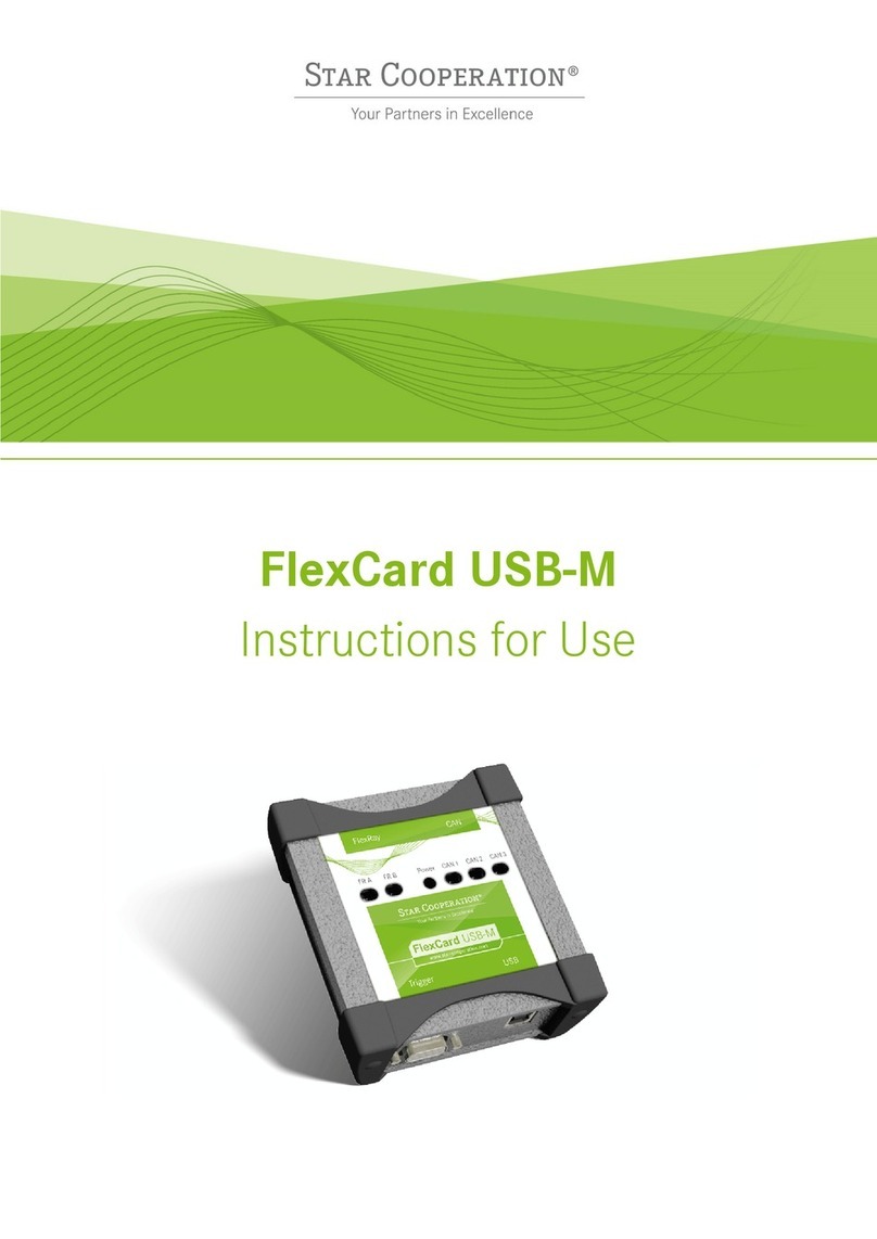
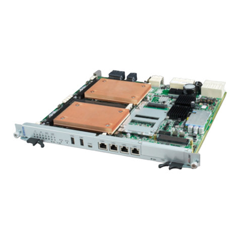
Star Cooperation FlexCard PXIe3 User manual

Created by STAR ELECTRONICS GmbH & Co. KG
Date created 2022-02-15 Date modified 2022-02-15 Page 2 of 40
3-0094-0A01-D10_Instructions_for_Use_FlexCard_PXIe3_and_PCIe3_D1V2-F.docx
Contact Information
STAR ELECTRONICS GmbH & Co. KG
A Company of the STAR COOPERATION Group
Jahnstraße 86
73037 Göppingen
Phone: +49 (0)7031 6288-5656
Phone: +49 (0)7031 6288-5330 (Support)
Sales: sales-ee@star-cooperation.com
Support: support-ee@star-cooperation.com
www.star-cooperation.com/ee-solutions
Company Data
STAR ELECTRONICS GmbH & Co. KG, registered offices: Göppingen, register court Ulm, HRA 721096
Partner liable to unlimited extent: STAR ELECTRONICS Verwaltungs-GmbH, registered offices: Göppingen, register
court Ulm, HRB 722565
Represented by the executive board: Rolf Wittig, Henning Lange
Copyright Notice
2022 STAR ELECTRONICS GmbH & Co. KG. All Rights Reserved.
No part of this document may be reproduced in any form (photocopy, microfilm or another procedure) without
prior written consent from STAR ELECTRONICS GmbH & Co. KG
Trademarks
All trademarks used in this document are the property of their respective owners.

Created by STAR ELECTRONICS GmbH & Co. KG
Date created 2022-02-15 Date modified 2022-02-15 Page 3 of 40
3-0094-0A01-D10_Instructions_for_Use_FlexCard_PXIe3_and_PCIe3_D1V2-F.docx
Disclaimer
The information contained in this document does not affect or change General Terms and Conditions of STAR
ELECTRONICS GmbH & Co. KG.STAR ELECTRONICS GmbH & Co. KG does not guarantee the completeness and
accuracy of the content of this document and assumes no responsibility for any errors which may appear in this
document or due to this document. The content of this document or the associated products are subject to
change without notice at any time.
Based on currently state of arts and science it is impossible to develop software that is bug-free in all
applications. Therefore, the product is only allowed to be used in the sense of the product use case described
herein.
STAR ELECTRONICS GmbH & Co. KG makes no warranty express or implied, as to this document or the
information content, materials or products for any particular purpose, nor does STAR ELECTRONICS GmbH & Co.
KG assume any liability arising out of the application or use of this product, and disclaims all liabilities, including
without limitation resulting damages, as permissible by applicable law.
All operating parameters which are provided in this document can vary in different applications or over time. The
herein described product solely is allowed to be used as described in chapter “Intended use”.
Without limiting the rights under copyright, no part of this document may be reproduced, stored in or introduced
into a retrieval system, or transmitted in any form or by any means (electronic, mechanical, photocopying,
recording, or otherwise), or for any purpose, without the express written consent of STAR ELECTRONICS GmbH &
Co. KG.
STAR ELECTRONICS GmbH & Co. KG may have patents, patent applications, trademarks, copyrights, or other
intellectual property rights covering subject matter in this document. Except as expressly stated in a written
license agreement from STAR ELECTRONICS GmbH & Co. KG,the furnishing of this document does not give you
any license to these patents, trademarks, copyrights, or other intellectual property.
Any semiconductor devices have an inherent chance of failure. You have to protect against injury, damage or loss
from such failures by incorporating safety design measures into your facility and equipment such as redundancy,
fire protection, and prevention of over-current levels and other abnormal operating conditions.
The safety and handling instructions in this document have to be followed strictly.
EC Conformity
The FlexCard PXIe3/PCIe3 complies with the essential requirements of the following applicable European Community
Directive(s) including current amendments, and carry the CE marking accordingly:
2014/30/EU EMC Directive
The following standard(s) have been used to assess the products:
EN 61000-4-2:2009
EN 61000-4-3:2006 + A1:2008 + A2:2010
EN 61000-4-4:2012
EN 61000-4-5:2014 + A1:2017
EN 61000-4-6: 2014
EN 61000-6-2:2005
EN 61000-6-3:2007 + A1:2011 (FlexCard PCIe3 only)
EN 61000-6-4:2007 + A1:2011 (FlexCard PXIe3 only)
EN 61326-1:2013
The FlexCard PXIe3 is a Class A product. Using the product in domestic environment may lead to electromagnetic
disturbances.
This product is compliant with the European Community Directive 2011/65/EC on the restriction of the use of
certain hazardous substances in electrical and electronic equipment (RoHS).

Created by STAR ELECTRONICS GmbH & Co. KG
Date created 2022-02-15 Date modified 2022-02-15 Page 4 of 40
3-0094-0A01-D10_Instructions_for_Use_FlexCard_PXIe3_and_PCIe3_D1V2-F.docx
UK Conformity
The FlexCard PXIe3/PCIe3 complies with the essential requirements of the following applicable UK Regulations
including current amendments, and carries the UK marking accordingly:
2016 Electromagnetic Compatibility Regulations
The following standard(s) have been used to assess the product:
EN 61000-4-2:2009
EN 61000-4-3:2006 + A1:2008 + A2:2010
EN 61000-4-4:2012
EN 61000-4-5:2014 + A1:2017
EN 61000-4-6: 2014
EN 61000-6-2:2005
EN 61000-6-3:2007 + A1:2011 (FlexCard PCIe3 only)
EN 61000-6-4:2007 + A1:2011 (FlexCard PXIe3 only)
EN 61326-1:2013
The FlexCard PXIe3 is designed, intended, and authorized for industrial use only. Using the product in domestic
environment may lead to electromagnetic disturbances.
This product is compliant with “the Restriction of the Use of Certain Hazardous Substances in Electrical and
Electronic Equipment Regulations 2012”.
Revision History
Document number: 3-0094-0A01-D10
Version
Date
Description
D1V0-3 06-Jun-2019 Preliminary version
D1V0-5 04-Nov-2019 Preliminary version: updated description for DIO
D1V0-12 09-Jun-2020 Preliminary version: added FlexCard PCIe3
D1V0-F 21-Jun-2021 First Release
D1V0a-F 21-Jun-2021 Added information about low-active trigger lines in FlexCard mode
D1V1a-F 06-Oct-2021 Added info about the FPGA images.
Added information about the Operating Modes.
D1V2-F 15-Feb-2022 Updated chapter EC Conformity
Added chapter UK Conformity
Related Hardware / Software Versions
Product
Reference No.
Version
Remarks
FlexCard PXIe3 hardware 3-0094-0B01 50
FlexCard PCIe3 hardware 3-0095-0B01 20

Created by STAR ELECTRONICS GmbH & Co. KG
Date created 2022-02-15 Date modified 2022-02-15 Page 5 of 40
3-0094-0A01-D10_Instructions_for_Use_FlexCard_PXIe3_and_PCIe3_D1V2-F.docx
Contents
1General ..................................................................................................................................................7
1.1 Intended User Group............................................................................................................................7
1.2 Intended Use .......................................................................................................................................7
1.3 Used Pictograms..................................................................................................................................8
1.4 Safety and Handling Instructions..........................................................................................................9
1.5 Meaning of Text Styles.......................................................................................................................10
2Product Description ........................................................................................................................... 11
2.1 FlexCard PXIe3/PCIe3 at a glance .....................................................................................................11
2.2 Accessory Parts .................................................................................................................................11
3Technical Data.................................................................................................................................... 13
3.1 Electrical Characteristics ...................................................................................................................13
3.2 Physical Characteristics .....................................................................................................................14
3.3 Environmental Conditions ..................................................................................................................14
3.4 Block Diagram ...................................................................................................................................14
3.5 Interfaces ..........................................................................................................................................15
3.5.1 Power FlexCard PXIe3 ........................................................................................................................15
3.5.2 Power FlexCard PCIe3........................................................................................................................16
3.5.3 Digital In/Output (DIO) (FlexDevice Mode) .........................................................................................16
3.5.4 Digital In/Output (DIO) (FlexCard Mode) ............................................................................................17
3.5.5 Digital In/Output (DIO) connector und LEDs.......................................................................................18
3.5.6 Bus Interfaces (Con 1 – 5)..................................................................................................................19
3.5.7 FlexTiny 1 – 5 Interfaces (Inside)........................................................................................................19
3.5.8 Reset Button and USER LEDs .............................................................................................................22
3.5.9 Factory Image ....................................................................................................................................23
4Getting Started................................................................................................................................... 24
4.1 Assembly and Line-up ........................................................................................................................24
4.1.1 Bus termination examples ..................................................................................................................24
4.1.2 Point-to-Point Bus Interface Connections ...........................................................................................24
4.1.3 Daisy Chain Bus Interface Connections ..............................................................................................24
4.1.4 Stub Bus Interface Connections .........................................................................................................25
4.2 Configuration and Operation ..............................................................................................................25
4.2.1 Termination .......................................................................................................................................25
4.3 Software Installation and Update .......................................................................................................25
4.3.1 Preconditions.....................................................................................................................................25
4.3.2 Installation on Microsoft Windows Operating Systems........................................................................26
4.3.3 Uninstallation on Microsoft Windows Operating Systems....................................................................28
4.4 Available Operating Modes.................................................................................................................29
4.4.1 FlexCard Mode...................................................................................................................................29
4.4.2 FlexDevice Mode................................................................................................................................29
4.4.3 Mixed Mode.......................................................................................................................................29
4.5 Change the Operating Mode...............................................................................................................29
4.5.1 Change the Mode from FlexDevice/Mixed Mode to FlexCard Mode ....................................................29
4.5.2 Change the Mode from FlexCard Mode to FlexDevice/Mixed Mode ....................................................31
4.6 FPGA images .....................................................................................................................................31
4.6.1 FlexDevice and Mixed Mode...............................................................................................................31
4.6.2 FlexCard Mode...................................................................................................................................31

Created by STAR ELECTRONICS GmbH & Co. KG
Date created 2022-02-15 Date modified 2022-02-15 Page 6 of 40
3-0094-0A01-D10_Instructions_for_Use_FlexCard_PXIe3_and_PCIe3_D1V2-F.docx
4.7 Firmware Update ...............................................................................................................................32
4.8 License Update..................................................................................................................................32
5Usage of the FlexCard PXIe3/PCIe3.................................................................................................. 33
5.1 WebAdmin UI .....................................................................................................................................33
5.2 Flash the FPGA ..................................................................................................................................34
6Shipping, Maintenance and Disposal................................................................................................. 35
7Troubleshooting ................................................................................................................................. 36
8Ordering Information ......................................................................................................................... 37
8.1 FlexCard PXIe3/PCIe3 .......................................................................................................................37
8.2 Accessory Parts .................................................................................................................................37
8.3 Related Documents............................................................................................................................37
9Appendix............................................................................................................................................. 38
9.1 Appendix A: Guideline for handling ESD sensitive Products.................................................................38
9.2 Appendix B: .......................................................................................................................................38
9.2.1 Acronyms and Abbreviations ..............................................................................................................38
9.2.2 List of Tables .....................................................................................................................................39
9.2.3 List of Figures ....................................................................................................................................39

Created by STAR ELECTRONICS GmbH & Co. KG
Date created 2022-02-15 Date modified 2022-02-15 Page 7 of 40
3-0094-0A01-D10_Instructions_for_Use_FlexCard_PXIe3_and_PCIe3_D1V2-F.docx
1General
1.1 Intended User Group
This product may only be used by expert technicians and/or engineers who are qualified and familiar with
electronic components and systems.
Each person involved with setup or operation of the product must
be a qualified technician or engineer
strictly adhere to this manual
receive a briefing by an authorized person
NOTICE
If you are unsure of how to use the product as intended or have any questions about
the use of the product, please discontinue use of the product immediately and
contact the STAR ELECTRONICS GmbH & Co. KG Support.
WARNING
The product may only be used by expert technicians and/or engineers who are
qualified and familiar with electronic components and systems!
The use of the product by non-professionals is not permitted and strictly forbidden!
1.2 Intended Use
The FlexCard PXIe3/PCIe3 is a testing equipment. It was developed to test the communication behavior of
automotive bus systems and Ethernet together with Electronics Control Units and sensors in a fully
controlled testing and/or laboratory environment.
For this intended use, the FlexCard PXIe3/PCIe3 offers the following options:
-Transmit and receive data (e.g. Use Case “Remaining Bus Simulation”).
-Exchange of data traffic between two or more bus systems (e.g. Use Case “Gateway”)
-Manipulation of data traffic (e.g. Use Case “Manipulation of signal values based on user
configuration”)
-Recording of data traffic (e.g. Use Case “Logging”)
Any deviation from the intended use and/or installation in a testing vehicle is only permitted with specific
prior written approval of STAR ELECTRONICS GmbH & Co. KG.

Created by STAR ELECTRONICS GmbH & Co. KG
Date created 2022-02-15 Date modified 2022-02-15 Page 8 of 40
3-0094-0A01-D10_Instructions_for_Use_FlexCard_PXIe3_and_PCIe3_D1V2-F.docx
WARNING
The FlexCard PXIe3/PCIe3 may be used to communicate with networked electronic
systems. E.g. FlexRay, CAN or Ethernet.
Any use of the product outside a fully controlled testing and/or laboratory
environment may result in death or serious injury due to unpredictable behavior of a
vehicle and/or potentially missing, deactivated, or malfunctioning safety devices on a
vehicle!
The user is responsible to ensure the safety of the entire system. This includes
amongst other things a safety shutdown.
NOTICE
The device is not a calibrated measurement device. STAR ELECTRONICS GmbH & Co.
KG accepts no liability whatsoever for the correctness of any measurement results.
WARNING
The FlexCard PXIe3/PCIe3 is NOT designed, intended, or authorized and may NOT be
used for or in connection with the following purposes and/or devices:
- use as part of medical systems
- life support applications
- aviation, space, nuclear, or military applications
- use in areas where combustible or explosive gas mixtures are likely to occur
- any other purposes / devices deviating from the intended use of the product
specified by STAR ELECTRONICS GmbH & Co. KG.
WARNING
The product may only be used by expert technicians and/or engineers who are
qualified and familiar with electronic components and systems!
The use of the product by non-professionals is not permitted and strictly forbidden!
1.3 Used Pictograms
The meaning of used pictograms is shortly described below.
Follow the specific instructions in the document where these pictograms are placed.

Created by STAR ELECTRONICS GmbH & Co. KG
Date created 2022-02-15 Date modified 2022-02-15 Page 9 of 40
3-0094-0A01-D10_Instructions_for_Use_FlexCard_PXIe3_and_PCIe3_D1V2-F.docx
WARNING
Used to indicate a potentially hazardous situation which,
if not avoided, could result in death or serious injury.
NOTICE
Used to indicate a situation which may result in an operating failure.
Damage of the product may occur, but there is no hazard of injury
if not avoided.
Reference
References to other documents.
Product marking which shows the compliance of the product with the European
Waste Electrical and Electronic Equipment Directive 2012/19/EU.
1.4 Safety and Handling Instructions
Please read the instructions for use carefully. To protect the device or the application against damage, or
to avoid personal injury the FlexCard PXIe3/PCIe3 has to be handled as described herein.
Changes or modifications of the FlexCard PXIe3/PCIe3 is not allowed for safety and warranty reasons!
STAR ELECTRONICS GmbH & Co. KG is not liable for any damages arising from non-observance of the
product information.
Follow the
a) specific safety and handling instructions placed at dedicated document positions
b) general safety and handling instructions below:
NOTICE
To prevent damage to the FlexCard PXIe3/PCIe3, or consequential damages:
Use only adapter cables from STAR ELECTRONICS GmbH & Co. KG for connecting
the FlexCard PXIe3/PCIe3.
High temperatures can damage the FlexCard PXIe3/PCIe3. Keep the FlexCard
PXIe3/PCIe3 away from heaters, stoves, fireplaces, and other sources of heat.
Do not expose the FlexCard PXIe3/PCIe3 to rain or use it near water.
Do not use the FlexCard PXIe3/PCIe3 in areas of explosion hazard.
NOTICE
To prevent irreversible damages to the FlexCard PXIe3/PCIe3:
Avoid any direct current flow through the housing of the device or the shield of the
Binder connectors!
Do not connect any other signals to the interfaces as described in the chapter 8.2
Accessory Parts. Ensure that all signals are within the specified range.
Attention: The warranty is lost if the device is damaged by not avoiding such current
flow or connecting any signals which are out of range.

Created by STAR ELECTRONICS GmbH & Co. KG
Date created 2022-02-15 Date modified 2022-02-15 Page 10 of 40
3-0094-0A01-D10_Instructions_for_Use_FlexCard_PXIe3_and_PCIe3_D1V2-F.docx
NOTICE
ESD (Electro Static Discharge) sensitive product
STAR ELECTRONICS GmbH & Co. KG products lacking protective enclosures are
subject to damage by ESD.
Take proper ESD precautions to avoid performance degradation or loss of
functionality!
Unpack, handle or operate these products only in environments where sufficient
precautionary measures have been taken in respect to ESD hazards. A guideline is
available in chapter 9.1.
Only appropriately trained personnel (such as electricians, technicians and
engineers) may handle and/or operate these products.
1.5 Meaning of Text Styles
In this document filenames are marked with a different text format.

Created by STAR ELECTRONICS GmbH & Co. KG
Date created 2022-02-15 Date modified 2022-02-15 Page 11 of 40
3-0094-0A01-D10_Instructions_for_Use_FlexCard_PXIe3_and_PCIe3_D1V2-F.docx
2Product Description
2.1 FlexCard PXIe3/PCIe3 at a glance
The multifunctional bus control unit FlexCard PXIe3/PCIe3 support multiple current and upcoming bus
systems and has numerous variable interfaces, so it covers most of the application fields where bus
interfaces are required. This device is appreciated by embedded software developers since it facilitates the
implementation and testing of even sophisticated gateway applications and prototyping functionalities.
Field of application
•Analyzing of bus data
•Vehicle diagnostics
•Remaining bus simulation
•Gateways between different automotive bus systems
•Signal manipulation
•Data logging
•Rapid prototyping
Technical Features FlexCard PXIe3/PCIe3
•Altera Cyclone V SOC (integrated ARM Cortex A9 dual core CPU)
•DDR3 RAM 1 GByte
•5 bus connectors with pluggable transceivers
•Up to 4 FlexRay controllers (4 Bosch E-Ray cores)
•Up to 8 FlexRay channels (4 channel A and 4 channel B) available on the connectors
•In each case 2 FlexRay cores can be connected internally (self-synchronization)
•Up to 10 CAN-HS bus interfaces
•Up to 10 CAN-FD bus interfaces
•Wakeup/sleep-support for bus transceiver (wakeup possible via FlexRay or CAN or local wakeup via
DIO)
•Up to 7 100 MBit/s Ethernet bus interfaces
•Up to 7 100BASE-T1 bus interfaces
•2 digital inputs or outputs (switchable between 5 V highspeed and 5/55 V high voltage resistance)
2.2 Accessory Parts
For usage of the FlexCard PXIe3/PCIe3, the following parts are necessary (not included in delivery):
•for the FlexCard PXIe3 a PXIe Rack
or
for the FlexCard PCIe3 a PC with PCIe interface
•Application software, e.g. FlexConfig RBS running under Windows 10 or Linux version
For further information about accessories for the FlexCard PXIe3/PCIe3 see chapter 8.2 Accessory Parts.

Created by STAR ELECTRONICS GmbH & Co. KG
Date created 2022-02-15 Date modified 2022-02-15 Page 12 of 40
3-0094-0A01-D10_Instructions_for_Use_FlexCard_PXIe3_and_PCIe3_D1V2-F.docx
NOTICE
Use only accessories from STAR ELECTRONICS GmbH & Co. KG listed in chapter 8.2
with the FlexCard PXIe3/PCIe3 to ensure proper function and for warranty reasons!
Other accessories without prior written consent of STAR ELECTRONICS GmbH & Co.
KG must not be used.

Created by STAR ELECTRONICS GmbH & Co. KG
Date created 2022-02-15 Date modified 2022-02-15 Page 13 of 40
3-0094-0A01-D10_Instructions_for_Use_FlexCard_PXIe3_and_PCIe3_D1V2-F.docx
3Technical Data
3.1 Electrical Characteristics
Min. Typ. Max.
Supply current PXI system
Operating 12V 150 mA 500 mA
Operation 5.0Vaux 250 mA 500 mA
Operation 3.3V 550 mA 1200 mA
Supply current PCI system
Operating 12V 150 mA 500 mA
Operation 3.3V 750 mA 1200 mA
Operation 3.3Vaux
100 mA
250 mA
The timings in this table are hardware specific and include no software timings!
DIO (Output) FlexDevice mode (high voltage resistance)
Turn-on time (IN = high)
VS= 5V, RLOAD = 2k, VLOAD = 12V, time to 90% ILOAD
- 2 µs 8 µs
Turn-off time (IN = low)
V
S
= 5V, R
LOAD
= 2k, V
LOAD
= 12V, time to 10% I
LOAD
- 2 µs 8 µs
DIO (Input) FlexDevice mode (high voltage resistance)
Operating mode high (ampl. factor 11/1)
- high level detection
-
low level detection
+24.0 V
0.0 V
-
-
+55.0 V
+12.0 V
Operating mode low (ampl. factor 1/1)
- high level detection
- low level detection
+2.2 V
0.0 V
-
-
+5.0 V
+1.7 V
Absolute maximum (low and high)
(non-operating)
-48.0 V - +60.0 V
DIO analog mode (Input) FlexDevice mode
Operating mode high (ampl. factor 11/1)
0.0 V
-
+55.0 V
Operating mode low (ampl. factor 1/1)
0.0 V
-
+5.0 V
Absolute maximum (low and high)
(non-operating)
-48.0 V - +60.0 V
DIO (Output) FlexCard mode (high-speed)
5V Turn-on time - 10 ns 40 ns
0V Turn-off time - 10 ns 40 ns
DIO (Input) FlexCard mode (high-speed)
high level detection
low level detection
+2.0 V
0.0 V
-
-
+5.5 V
+0.8 V
Absolute maximum (low and high)
(non-operating)
-0.5 V - +6.5 V

Created by STAR ELECTRONICS GmbH & Co. KG
Date created 2022-02-15 Date modified 2022-02-15 Page 14 of 40
3-0094-0A01-D10_Instructions_for_Use_FlexCard_PXIe3_and_PCIe3_D1V2-F.docx
Min. Typ. Max.
5V Turn-on time - 100 ns 180 ns
0V Turn-off time - 100 ns 180 ns
Table 1: Electrical characteristics
3.2 Physical Characteristics
Connectors
DIO 1 – 2 MMCX – 1 pol.
Con 1 – 5 Binder series 702/712 – 8 pol.
Mounting position Mechanical limitations: none
Electrical limitations: none
Temperature limitations: none
Weight approx., without FlexTiny 180 g
FlexCard PXIe3: Dimensions approx. L
x W x H (including connectors,
including slot metal plate, including the
ejection lever)
210 mm * 130 mm * 3U
FlexCard PCIe3: Dimensions approx. L
x W x H (including connectors,
including slot metal plate)
172 mm * 125 mm * 18 mm
Table 2: Physical characteristics
3.3 Environmental Conditions
NOTICE
ATTENTION: An over temperature may damage the FlexCard PXIe3/PCIe3, if the
temperature is higher than the allowed 70°C!
Temperature (FlexCard PXIe3)
Operating: -20°C – +70°C
Non-operating: -40°C – +85°C
Storage: -40°C – +85°C
Temperature (FlexCard PCIe3)
Operating: -40°C – +70°C
Non-operating: -40°C – +85°C
Storage: -40°C – +85°C
IP-Code None
Relative Humidity
0% – 90% r. H., non-condensing
Vibration resistance (for FlexTiny relay)
Destruction: 10 – 55 Hz (Double amplitude of 5 mm)
Functional: 10 – 55 Hz (Double amplitude of 3.3 mm, detection
time: 10 µs)
Shock resistance (for FlexTiny relay)
Destruction: 1,000 m/s2(Half-wave pulse of sine wave: 6 ms.)
Functional: 750 m/s2(Half-wave pulse of sine wave: 6 ms;
detection time: 10 µs.)
Table 3: Environmental conditions
3.4 Block Diagram
Functional overview of the FlexCard PXIe3/PCIe3

Created by STAR ELECTRONICS GmbH & Co. KG
Date created 2022-02-15 Date modified 2022-02-15 Page 15 of 40
3-0094-0A01-D10_Instructions_for_Use_FlexCard_PXIe3_and_PCIe3_D1V2-F.docx
Figure 1: Block diagram of FlexCard PXIe3
Figure 2: Block diagram of FlexCard PCIe3
3.5 Interfaces
3.5.1 Power FlexCard PXIe3
The FlexCard PXIe3 uses the 12 V, 3.3 V and 5.0 Vaux from the PXIe Rack.

Created by STAR ELECTRONICS GmbH & Co. KG
Date created 2022-02-15 Date modified 2022-02-15 Page 16 of 40
3-0094-0A01-D10_Instructions_for_Use_FlexCard_PXIe3_and_PCIe3_D1V2-F.docx
The 5.0 Vaux is used in case of power saving. Some bus transceivers support an UBAT supply input that
supplies the bus drivers in sleep mode. The respective UBAT supply pin of the bus driver ICs is connected
to the permanent supplied voltage.
3.5.2 Power FlexCard PCIe3
The FlexCard PCIe3 uses the 12 V, 3.3 V and 3.3 Vaux from the PCIe PC.
The 3.3 Vaux is used in case of power saving. Some bus transceivers support an UBAT supply input that
supplies the bus drivers in sleep mode. The respective UBAT supply pin of the bus driver ICs is connected
to the permanent supplied voltage.
3.5.3 Digital In/Output (DIO) (FlexDevice Mode)
The FlexCard PXIe3/PCIe3 can get or set digital signals like a FlexDevice-S or L in the DIO FlexDevice
mode
NOTICE
A relay switch between the FlexCard mode and the FlexDevice mode. Be careful
when switching from FlexDevice mode to FlexCard mode while signals are
connected.
A dual Low-Side-Switch BTS3408 from Infineon drives the digital output of the FlexCard PXIe3/PCIe3.
Connect the load between the supply voltage and the DIO[x] pin. The BTS3408 is a 60 V with 550 mA
switch.
For each channel, a 100 kOhm resistor in series to the input from a rail-to-rail operational amplifier (OP)
LT1490 from Analog Device protects the digital inputs of the FlexCard PXIe3/PCIe3. This OP is internally
protected from -18.0 to 44.0 V. To expand the range from input from 5.0 to 55.0 V a controllable 11/1
voltage divider is implemented in the FlexCard PXIe3/PCIe3. The propagation delay of the input signal to
the processor is >15 µs.
The following figure shows the functional overview of the DIO in/output logic in the FlexDevice mode
10
DIO 2 10 +
–½
DIO 1 +
–
10
10
1
digital + analog 1
BTS3408
nFault
IN[1]/IN[2]
ENA
DIO range
½
LT1490
OU T [1]
OU T [2]
Controller
digital + analog 2
Intern
µC & ADI
Extern
MMCX
connector
Figure 3: FlexDevice mode DIO in-/output internal overview

Created by STAR ELECTRONICS GmbH & Co. KG
Date created 2022-02-15 Date modified 2022-02-15 Page 17 of 40
3-0094-0A01-D10_Instructions_for_Use_FlexCard_PXIe3_and_PCIe3_D1V2-F.docx
NOTICE
The DIO output is NOT a push/pull driver, it can only pull down the signal.
Put the load (LED, resistor, motor, etc.) between a positive power supply (Vbb) and
the DIOx pin from the FlexCard PXIe3/PCIe3
The following figure is the block diagram for the BTS3408 out of the datasheet. The BTS3408 has two
channels, IN1 drives OUT1 and IN2 drives OUT2. EN enables both outputs.
Figure 4: DIO output BTS3408 functional block diagram
Connector
Pin
Name / Function
Range
DIO
MMCX
1 contact
NOTICE
Case DIO_GND Digital ground
1 DIO[1/2]
Digital in/output or
analog input
Operating: 0.0 – +5.0/55.0 V
Switching thresholds:
(operating at 0 – +5 V): +2.2 V
(operating at 0 – +55 V): +24 V
Absolute Maximum:
FlexDevice Mode: -48 – +60 V
FlexCard Mode: -0.5 – +6.0 V
Table 4: DIO connector electrical specification in FlexDevice mode
3.5.4 Digital In/Output (DIO) (FlexCard Mode)
For synchronization purposes in FlexCard mode, the FlexCard PXIe3/PCIe3 provides two 5V tolerant TTL-
compatible trigger connectors (DIO[1] and DIO[2]) on the front panel.

Created by STAR ELECTRONICS GmbH & Co. KG
Date created 2022-02-15 Date modified 2022-02-15 Page 18 of 40
3-0094-0A01-D10_Instructions_for_Use_FlexCard_PXIe3_and_PCIe3_D1V2-F.docx
NOTICE
A relay switch between the FlexCard mode and the FlexDevice mode. Be careful
when switching from FlexDevice mode to FlexCard mode while signals are
connected.
The signals must be between 0.0 V and 5.0 V!
The FlexCard PXIe3/PCIe3 could receive and generate trigger events on both trigger connectors. This
feature allows e.g. a synchronization of different bus analyzing devices.
Physically, the triggers are MMCX-male-connector for coax-cables. The electrical characteristic of this
output is described in Table 5. In output direction the trigger line is low active. When a pulse is generated,
the output voltage drops from 5V to 0V, stays 0V for 8 microseconds and then returns back to 5V.
Table 5: DIO connector electrical specification in FlexCard Mode
Reference
Detailed information about how the trigger events are used with the FlexCard
PXIe3/PCIe3 can be found in the FlexCard API Documentation.
3.5.5 Digital In/Output (DIO) connector und LEDs
Between the two DIO connectors are two pairs of yellow and blue LEDs for visualization of user states or
debugging purposes. For more information about the FlexCard PXIe3/PCIe3 DIO LEDs refer to the manual
of the used application (e.g. FlexConfig RBS).
Figure 5: DIO connectors with LEDs
Connector DIO
Pin
Signal Name
Description
1
DIO[1/2]
Digital 1/2 in/output
Case
Ground
Ground
Table 6: Pinout DIO connector
Connector
Pin
Name / Function
Range
DIOx
MMCX
1 contact
NOTICE
Case DIO_GND Digital ground
1 DIO[1/2]
Digital in/output or
analog input
Operating: 0.0 – +5.0 V
Input high voltage: +2.4 V
Input low voltage: +0.8 V
Absolute Maximum:
FlexCard Mode: -0.5 – +6.0 V
FlexDevice Mode: -48 – +60 V
DIO[2]
DIO[1]

Created by STAR ELECTRONICS GmbH & Co. KG
Date created 2022-02-15 Date modified 2022-02-15 Page 19 of 40
3-0094-0A01-D10_Instructions_for_Use_FlexCard_PXIe3_and_PCIe3_D1V2-F.docx
3.5.6 Bus Interfaces (Con 1 – 5)
NOTICE
To prevent any ESD damage to the device, the allowed maximum cable length for
the bus interfaces is 30m!
The FlexCard PXIe3/PCIe3 has five bus interface connectors. Each connector includes different buses
depending on mounted FlexTiny III module. Possible FlexTiny III variants are FlexRay, CAN-FD, LIN/SENT,
ETH-switched (100MBit) or 100BASE-T1. For detailed information, see chapter 3.5.7 FlexTiny 1 – 5
Interfaces (Inside) and 8.2 Accessory Parts.
The connectors are labeled with their corresponding number (see figure below). The connector next to Con
1 is Con2 and so on. Below every connector is a pair of two LEDs, a green and a red LED for visualization of
user states or debugging purposes. The right LEDs shows channel[A] the left LEDs shows channel[B]. For
more information about the LEDs refer to manual of the used application (e.g. FlexConfig RBS).
Figure 6: Con 1 – 5 connectors
Reference
The pinout from the connector depends on the mounted FlexTiny III module. See the
document Instructions for Use FlexTiny3 [1] for more information.
3.5.7 FlexTiny 1 – 5 Interfaces (Inside)
The FlexCard PXIe3/PCIe3 has five FlexTiny III module interface connectors. Each slot supports different
FlexTiny III modules. Possible types are: FlexRay, CAN-FD, LIN/SENT, ETH-switched (100MBit) or 100BASE-
T1. For other interfaces contact STAR ELECTRONICS GmbH & Co. KG.
If necessary, it is possible to change the equipped FlexTiny III modules to different variants. Before
changing FlexTiny III modules, unmount the FlexCard PXIe3/PCIe3 from the rack or PC to make sure that it
is unpowered.
The Ethernet and 100BASE-T1 FlexTiny III need a full interface for a two-channel functionality, which is only
available for the sockets 2 and 4. The sockets 1, 3 and 5 support only one channel.
The following figure and table show the features of each Tiny slot.
CH[A]
CH[B]

Created by STAR ELECTRONICS GmbH & Co. KG
Date created 2022-02-15 Date modified 2022-02-15 Page 20 of 40
3-0094-0A01-D10_Instructions_for_Use_FlexCard_PXIe3_and_PCIe3_D1V2-F.docx
FlexCard-PXIe3
SOC 1 (FD-L & L²)
Tiny 5
Tiny 1
FPGA ARM
Cor tex A 9
BD
ETH
Reduced
PCIe
Bus
ETH
Tiny 2
Full
Bus
Tiny 4
ETH
CC_IF
Tiny 3
Bus
CC_IF
ETH
Full
Bus
Reduced
Bus
ETH-CC
J3
J4Con 1
Con 2
Con 3
Con 4
Con 5
CC-IF
CC-IF
CC-IF
Reduced
BD
BD
BD
BD
Power
Figure 7: FlexTiny III interface 1 – 5 overview (the FlexCard PXIe3 is shown, the FlexCard PCIe3 is similarly)
The size of the bus in the above figure depends on the used Tiny, 8 signal lines are available.
FlexTiny III
Transceiver
Socket 1
Socket 2
Socket 3
Socket 4
Socket 5
LIN/SENT
TJA1021
All Ch.
All Ch.
All Ch.
All Ch.
All Ch.
CAN FDx4
NXP TJA1044G
4 Ch.
4 Ch.
4 Ch.
4 Ch.
4 Ch.
CAN FD
NXP TJA1081B
2 Ch.
2 Ch.
2 Ch.
2 Ch.
2 Ch.
FlexRay
NXP TJA1145T/FD
2 Ch.
2 Ch.
2 Ch.
2 Ch.
2 Ch.
100 Mbit Ethernet
Marvell 88E6350R
1 Ch.
2 Ch.
1 Ch.
2 Ch.
1 Ch.
100BASE-T1
Broadcom BCM89810
1 Ch.
2 Ch.
1 Ch.
2 Ch.
1 Ch.
1000BASE-T1
Marvell 88Q2112
1 Ch.
2 Ch.
1 Ch.
1 Ch.
1 Ch.
Table 7: FlexTiny III interface 1 – 5 supported channels for FlexCard PXIe3/PCIe3
This manual suits for next models
1
Table of contents
Other Star Cooperation Network Hardware manuals

