Star Lake CPT330B User manual

User’s Manual
Revision Date: April. 15. 2020
CPT330B
Rugged IOT Edge Computer with Intel®
Core™i7-9700TE

CPT330B User’s Manual
Revision Date: April. 15. 2020
Safety Information
Electrical safety
Operation safety
Statement

CPT330B User’s Manual
Revision Date: April. 15. 2020
Revision History
Packing list
Item
Description
Q’ty
1
CPT330B Embedded System
1
2
Driver CD
1
3
3-pin Terminal Block Power Connector (For DC Power Input)
1
If any of the above items is damaged or missing, please contact your local distributor.

CPT330B User’s Manual
Revision Date: April. 15. 2020
Table Contents
SAFETY INFORMATION.................................................................................................................................................1
..............................................................................................................................................................
..............................................................................................................................................................
........................................................................................................................................................................
REVISION HISTORY ...................................................................................................................................................2
PACKING LIST ...........................................................................................................................................................2
TABLE CONTENTS .....................................................................................................................................................3
CHAPTER 1: PRODUCT INTRODUCTION ....................................................................................................................4
..............................................................................................................................................................
........................................................................................................................................
..........................................................................................................................................
.............................................................................................................................................
CHAPTER 2: JUMPERS AND CONNECTORS................................................................................................................8
...........................................................................................................................................................
.....................................................................................................................................................
................................................................................................................................................................
.............................................................................................................................
.........................................................................................................................................................
...................................................................................................................................................
....................................................................................................................................................
..............................................................................................................................................................
...........................................................................................................................
-............................................................................................................................
- ..........................................................................................................................
- ...................................................................................
..................................................................................................................................................
CHAPTER 3: AMI BIOS UTILITY ...............................................................................................................................12
...................................................................................................................................................................
.......................................................................................................................................................
...............................................................................................................................................................
.........................................................................................................................................................
................................................................................................................................................
..........................................................................................................................................
.........................................................................................................................................
.......................................................................................................................................................
...................................................................................................................................
.................................................................................................................................
.......................................................................................................................................
...........................................................................................................................................................
....................................................................................................................................................
...................................................................................................................................................
................................................................................................................................................................
......................................................................................................................................................

CPT330B User’s Manual
Revision Date: April. 15. 2020
Chapter 1: Product Introduction
1.1 Key Features
--
--
COM
2 x RS232 / 422 / 485 (Support Power 5V / 12V)
Ethernet
2 x RJ45
USB
4 x USB 3.1 Gen 2, 2 x USB 2.0
PS/2
1
DisplayPort
1 x 20Pin DisplayPort connector, resolution up to 4096x2160@60Hz
DVI-I
1 x 20Pin DVI-I connector, resolution up to 2560x1600@60Hz
Terminal Block
1 x 2Pin Terminal Block Remote Power ON/OFF
1 x 2Pin Terminal Block Remote Reset
1 x 4Pin Terminal Block External FAN Connector
1 x 3Pin Terminal Block Power Input
Audio
1 x Mic-in, 1 x Line-out
-
(ambient with air flow)
-
-

CPT330B User’s Manual
Revision Date: April. 15. 2020
1.2 Front Panel I/O Placement
1.3 Rear Panel I/O Placement

CPT330B User’s Manual
Revision Date: April. 15. 2020
-
--
-
CPT330B User’s Manual
Revision Date: April. 15. 2020
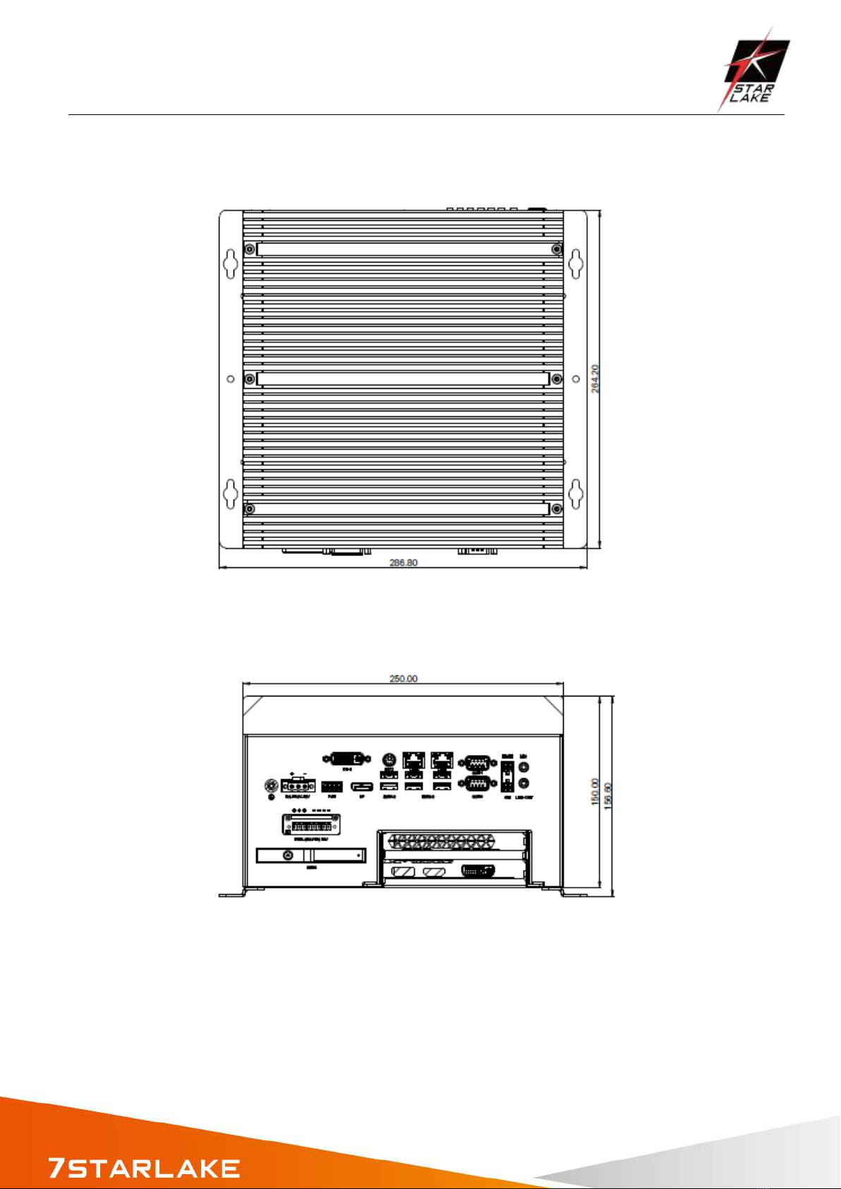
1.4 Mechanical Dimensions

CPT330B User’s Manual
Revision Date: April. 15. 2020
Chapter 2: Jumpers and Connectors
2.1 Jumper Setting
Power Supply Mode
Pin
Signal
UP
ATX mode
Down
AT mode
COM Mode
Switch setting
Mode
1
2
1-2COM 1
RI
ON
ON
5V
ON
OFF
12V
OFF
ON
Switch setting
Mode
3-4COM 2
RI
ON
ON
5V
ON
OFF
12V
OFF
ON
2.2 Internal Connector Pin Definition
SATA Connector
Pin
Signal Name
P1
VCC3
P2
VCC3
P3
VCC3
CPT330B User’s Manual
Revision Date: April. 15. 2020
P4
GND
P5
GND
P6
GND
P7
VCC
P8
VCC
P9
VCC
P10
GND
P11
RES
P12
GND
P13
+12V
P14
+12V
P15
+12V
S1
GND
S2
SATAHDR_TXP0_C
S3
SATAHDR_TXN0_C
S4
GND
S5
SATAHDR_RXN0_C
S6
SATAHDR_RXP0_C
S7
GND
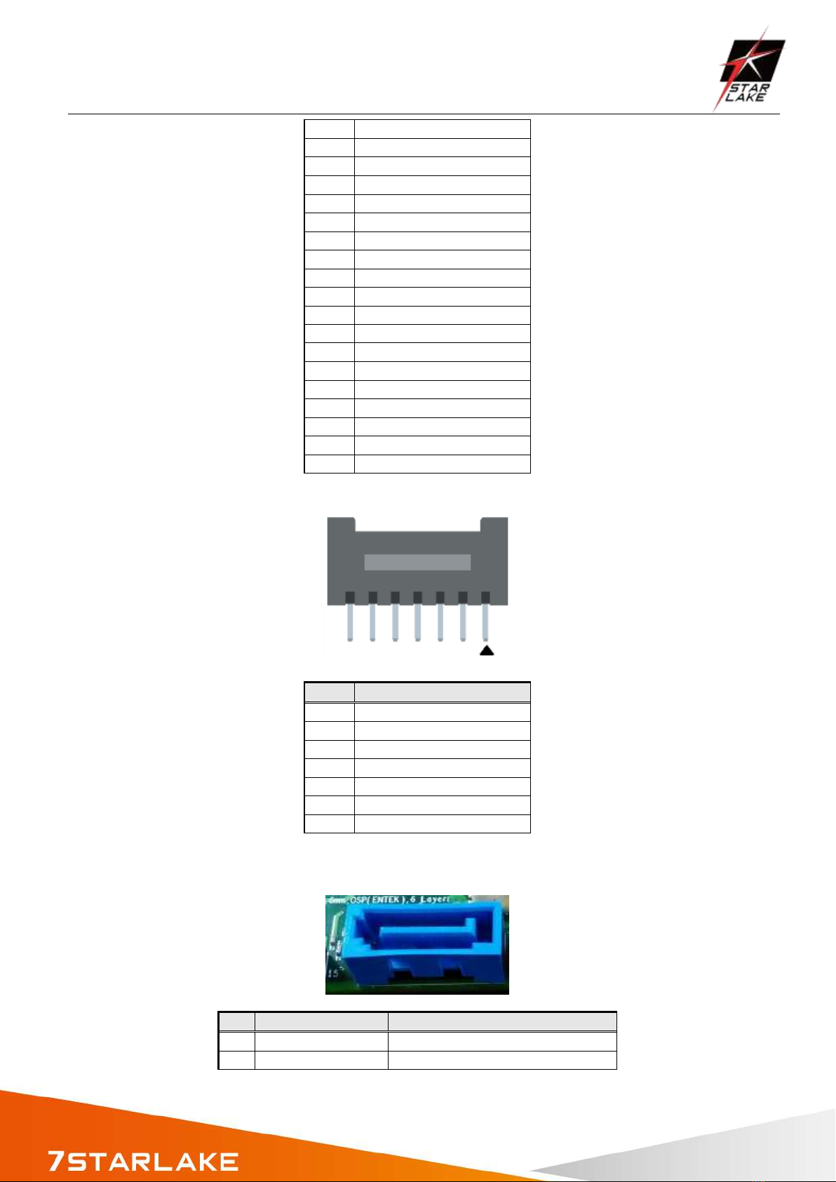
SATA Power Header
Pin
Signal Name
1
VCC3
2
GND
3
VCC
4
VCC
5
GND
6
+12V
7
+12V
SATA Signal Header
Pin
Signal Name
Description
1
GND
Ground
2
SATAHDR_TXP_C
SATA DATA Transmit(positive)

CPT330B User’s Manual
Revision Date: April. 15. 2020
3
SATAHDR_TXN_C
SATA DATA Transmit(negative)
4
GND
Ground
5
SATAHDR_RXN_C
SATA DATA Receive(negative)
6
SATAHDR_RXP_C
SATA DATA Receive(positive)
7
GND
Ground
8
G1
GND
9
G2
GND
Fan Header
Pin
Signal
1
Ground
2
+12V
3
CPU_FAN_TACH
4
CPU_FAN_CTRL
2.3 External Connector Pin Definition
3-pin terminal block for DC Input
Pin
Signal
1
DC IN
2
Ignition (IGN)
3
GND
4-pin Terminal Block for PWM Fan
Pin
Signal
CPT330B User’s Manual
Revision Date: April. 15. 2020
Pin
Signal
1
Ground
2
+12V
3
System_FAN_TACH
4
SYSTEM_FAN_CTRL
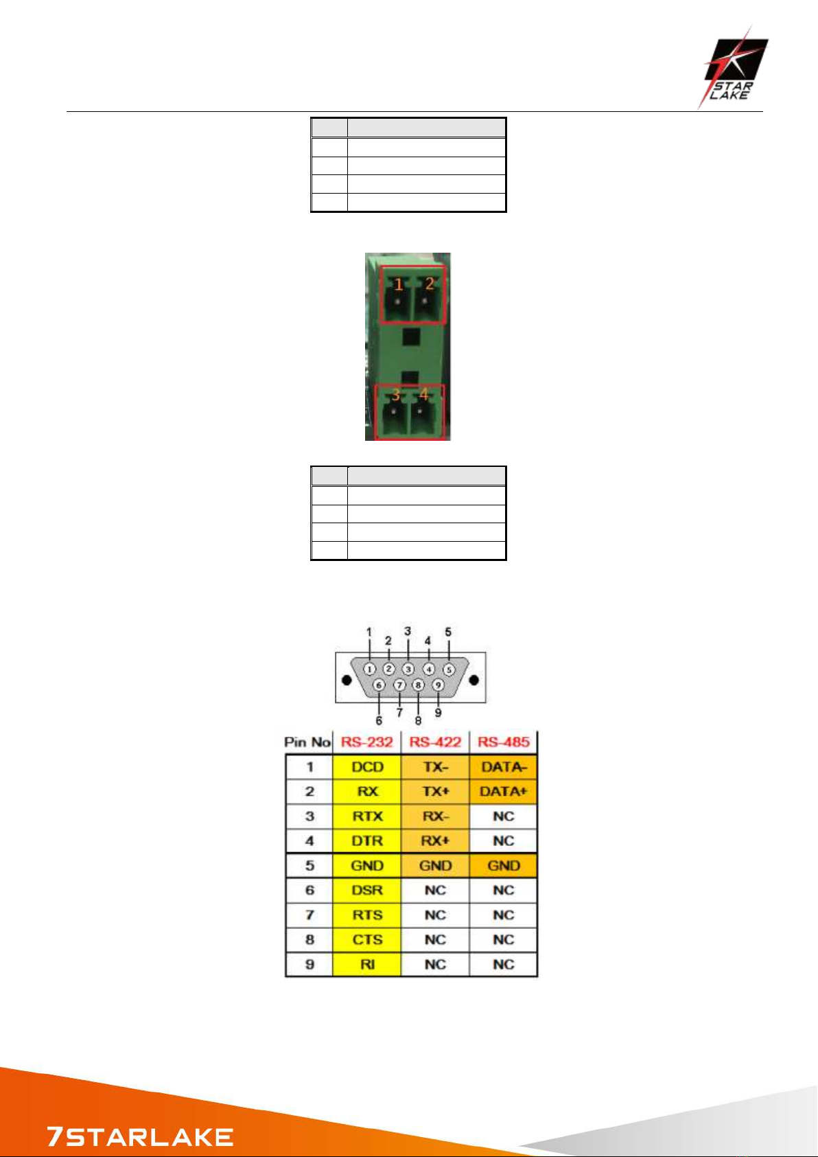
2-pin Terminal Block for Remote Power ON/OFF and Reset
Pin
Signal
1
Ground
2
EXT Reset
3
Ground
4
EXT_PWRBT_ON/OFF
COM Pin definition

CPT330B User’s Manual
Revision Date: April. 15. 2020
Chapter 3: AMI BIOS UTILITY
3.1 Starting
3.2 Navigation Keys
-
-
-
CPT330B User’s Manual
Revision Date: April. 15. 2020
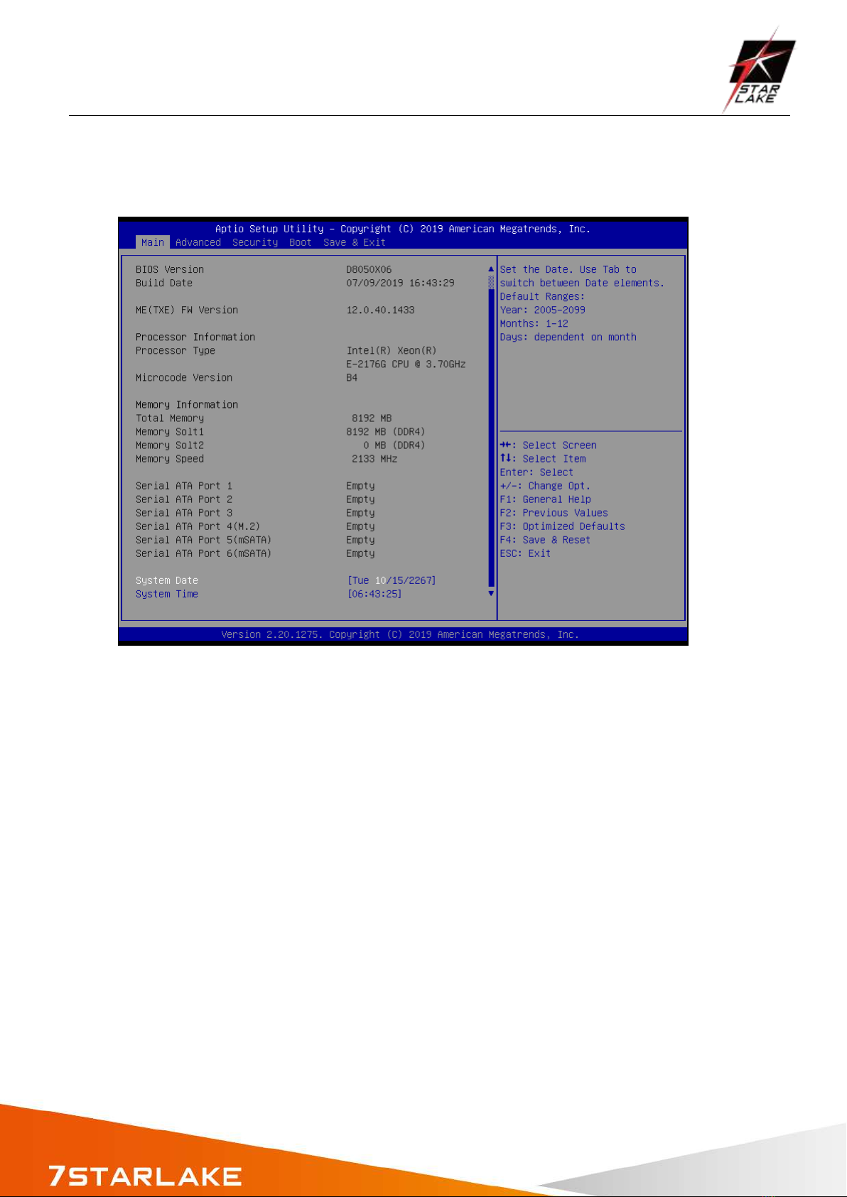
3.3 Main Page
System Date
System Time
Note:-
Access Level

CPT330B User’s Manual
Revision Date: April. 15. 2020
3.4 Advanced Page
Setting incorrect field values
may cause the system to malfunction.
Advanced
Description
►
►
►
►
►
►
►
►
►

CPT330B User’s Manual
Revision Date: April. 15. 2020
3.4.1 Onboard Device
►Onboard Devices
Value
Onboard Device Configuration
-
-
-
-

CPT330B User’s Manual
Revision Date: April. 15. 2020
3.4.2 CPU Configuration
►CPU Configuration
Value
CPU Configuration Parameters

CPT330B User’s Manual
Revision Date: April. 15. 2020
3.4.3 Trusted Computing
►Trusted Computing
Value
Trusted Computing Settings

CPT330B User’s Manual
Revision Date: April. 15. 2020
3.4.4 WatchDog
►WatchDog
Value
WatchDog Configuration
3.4.5 Super IO Configuration

CPT330B User’s Manual
Revision Date: April. 15. 2020
►Super IO Configuration
Value
System Super IO Chip Parameters.
Super IO Configuration
Super IO Chip
NCT6116D
►Serial Port 1 Configuration
Value
Set Parameters of Serial Port 1
(COMA)
Serial Port 1 Configuration
Serial Port
Disabled / [Enabled]
Enable or Disable Serial Port (COM)
Device Settings
IO=3F8h; IRQ=4
Change settings
[Auto] / IO=3F8h; IRQ=4
/ IO=3F8h; IRQ=3, 4, 5, 6, 7, 9, 10,
11, 12
/ IO=2F8h; IRQ=3, 4, 5, 6, 7, 9, 10,
11, 12
/ IO=3E8h; IRQ=3, 4, 5, 6, 7, 9, 10,
11, 12
/ IO=2E8h; IRQ=3, 4, 5, 6, 7, 9, 10,
11, 12
Select an optimal settings for Super
IO Device
Mode Configuration
[RS232] / RS485 / RS422
Configure serial port as
RS232/RS422/RS485.
►Serial Port 2 Configuration
Value
Set Parameters of Serial Port 2
(COMB)
Table of contents
Other Star Lake Desktop manuals

Star Lake
Star Lake SR700 User manual

Star Lake
Star Lake SCH-406 User manual

Star Lake
Star Lake AV710 User manual

Star Lake
Star Lake ROC286BB User manual

Star Lake
Star Lake SR10-SCH User manual

Star Lake
Star Lake SCH-406 User manual

Star Lake
Star Lake SR10B User manual

Star Lake
Star Lake THOR200-D15EG User manual
Popular Desktop manuals by other brands

Compaq
Compaq BL10e - HP ProLiant - 512 MB RAM introduction

DIGITAL YACHT
DIGITAL YACHT Aqua PC Series Installation & quick start guide

Lenovo
Lenovo ThinkCentre M52 Gyorstájékoztató

HP
HP Pavilion w1000 - Desktop PC Technical specifications

Sony
Sony VGC-JS155J/S Specifications

IBM
IBM NetVista A20 quick reference


