Star Lake SR10B User manual

User’s Manual
Revision Date: Oct. 07. 2016
SR10B
MIL-STD Rugged Computer
User’s Manual

SR10B User’s Manual
Revision Date: Oct. 07. 2016
1
Safety Information
Electrical safety
To prevent electrical shock hazard, disconnect the power cable from the electrical outlet before
relocating the system.
When adding or removing devices to or from the system, ensure that the power cables for the
devices are unplugged before the signal cables are connected. If possible, disconnect all power cables
from the existing system before you add a device.
Before connecting or removing signal cables from the motherboard, ensure that all power cables are
unplugged.
Seek professional assistance before using an adapter or extension cord. These devices could interrupt
the grounding circuit.
Make sure that your power supply is set to the correct voltage in your area.
If you are not sure about the voltage of the electrical outlet you are using, contact your local power
company.
If the power supply is broken, do not try to fix it by yourself. Contact a qualified service technician or
your local distributor.
Operation safety
Before installing the motherboard and adding devices on it, carefully read all the manuals that came
with the package.
Before using the product, make sure all cables are correctly connected and the power cables are not
damaged. If you detect any damage, contact your dealer immediately.
To avoid short circuits, keep paper clips, screws, and staples away from connectors, slots, sockets and
circuitry.
Avoid dust, humidity, and temperature extremes. Do not place the product in any area where it may
become wet.
Place the product on a stable surface.
If you encounter any technical problems with the product, contact your local distributor
Statement
All rights reserved. No part of this publication may be reproduced in any form or by any means,
without prior written permission from the publisher.
All trademarks are the properties of the respective owners.
All product specifications are subject to change without prior notice

SR10B User’s Manual
Revision Date: Oct. 07. 2016
2
Revision History
Revision
Date (yyyy/mm/dd)
Changes
V0.1
2016/08/10
Initial Release
Version 1.1
2016/10/7
New vibration isolation design
Add WatchDog Function
Packing list
□SR10B MIL-STD Rugged Computer
□Vibration Isolation Base
Accessories Kit
□Terminal block 4 PIN x 1pcs
□Screw Package
□CD (Driver + User’s Manual)
Ordering Information
Model Number
Description
SR10B-UT
Intel® QM87 MIL-STD Fanless Rugged System with Intel® Core i7-4700EQ
Haswell Processor, 9V to 36V DC-in. Wide Temp -40 to 70°C
With a vibration isolation base.

SR10B User’s Manual
Revision Date: Oct. 07. 2016
3
Table of contents
Safety Information .............................................................................................................................................1
Electrical safety..............................................................................................................................................1
Operation safety ............................................................................................................................................1
Statement......................................................................................................................................................1
Revision History..................................................................................................................................................2
Packing list..........................................................................................................................................................2
Accessories Kit....................................................................................................................................................2
Ordering Information.........................................................................................................................................2
Chapter 1: Product Introduction ........................................................................................................................5
1-1 Key Features ............................................................................................................................................5
1.2 Front Panel Components..........................................................................................................................7
1.3 Back Panel Components...........................................................................................................................8
1.4 Mechanical Dimensions ...........................................................................................................................9
Chapter 2: Jumpers and Connectors ................................................................................................................10
2.1 Front Panel Connector Pin Definitions................................................................................................10
2.3 Internal Connector and Jumper Setting .................................................................................................13
Chapter 3: Installation......................................................................................................................................14
3.1 HDD tray..............................................................................................................................................14
3.3 Vibration Isolation Base ......................................................................................................................15
Chapter 4: AMI BIOS UTILITY............................................................................................................................16
4.1 Starting...................................................................................................................................................16
4.3 Main Menu.............................................................................................................................................17
4.4 Advanced Menu.....................................................................................................................................18
4.4.1 PCI Subsystem Settings....................................................................................................................19
4.4.2 ACPI Settings....................................................................................................................................21
4.4.3 CPU configuration............................................................................................................................22

SR10B User’s Manual
Revision Date: Oct. 07. 2016
4
4.4.4 SATA Configuration..........................................................................................................................28
4.4.5 Intel Rapid Start Technology............................................................................................................33
4.4.6 PCH-FW Configuration.....................................................................................................................34
4.4.7 Intel Anti-Theft Technology Configuration ......................................................................................35
4.4.8 AMT Configuration ..........................................................................................................................36
4.4.9 USB Configuration ...........................................................................................................................38
4.4.10 IT8786 Super IO Configuration ......................................................................................................39
4.4.11 IT8786 HW Monitor.......................................................................................................................41
4.4.12 Serial Port Console Redirection .....................................................................................................42
4.4.13 Network Stack ...............................................................................................................................43
4.5 Chipset ...................................................................................................................................................45
4.5.1 PCH IO configuration .......................................................................................................................46
4.5.2 System AGENT SA............................................................................................................................56
4.6 Boot........................................................................................................................................................58
4.7 Security ..................................................................................................................................................59
4.8 Save and Exit..........................................................................................................................................60

SR10B User’s Manual
Revision Date: Oct. 07. 2016
5
Chapter 1: Product Introduction
1-1 Key Features
System
CPU
Intel® Core™ i7 Haswell , BGA type Core i7-4700EQ (4C x 2.4/1.7
GHz), 6M Cache (47W)
Chipset
Intel® QM87 PCH
Ethernet Chipset
Intel® I210-IT & I217-LM GbE
Memory
1 x DDR3 1600 XR-DIMM up to 8 GB with ECC
Expansion Slot
1 x mPCIe w/ SIM slot
Storage Device
1 x SATA III 6 Gb/s 2.5" SSD/HDD
Front I/O
Power Button
1 x dual color backlight button
Power LED
1
HDD LED
1
LAN Active/Speed LED
4
USB
2 x USB 3.0
COM
2 x RS232 with 5V/12V selectable
Power
1 x Terminal Block
Rear I/O
Ethernet
4 x RJ45
COM
2 x RS232/422/485 with 5V/12V selectable (Default RS232)
USB
2 x USB 3.0
DVI-I
1 x 29-pin DVI-I connector
DisplayPort
2 x 20-pin DP connector
Audio
1 x MIC, 1 x Line out
Display
Display Interface
1 x DVI-I connectors (female); resolution up to 1920 x 1200@60
Hz, 2 x DisplayPort : DisplayPort connectors (female); resolution
up to 3840 x 2160@60 Hz
Graphics Controller
Onboard Intel® HD 4600 graphics
Mechanical & Environment
Power Requirements
9V to 36V DC-in, AT/ATX mode supports with power delay on/off
Dimension (W x H x D)
262 x 149 x 66 mm (10.31" x 5.87" x 2.60")
Weight
4.32kg (9.52lbs)
Operating Temp.
-40 to 70°C (ambient with air flow)
Storage Temp.
-40 to 85°C
SR10B User’s Manual
Revision Date: Oct. 07. 2016
6
Relative Humidity
5% to 95%, non-condensing
Serial Interface & Signals
Serial Standards
1x RS-232/422/485 port, Jumper-selectable (DB9 male)
RS-232
TxD, RxD, DTR, DSR, RTS, CTS, DCD, GND
RS-422
TxD+, TxD-, RxD+, RxD-, GND
RS-485-4w
TxD+, TxD-, RxD+, RxD-, GND
RS-485-2w
Data+, Data-, GND
Standards and
Certifications
MIL-STD-810G Test
Method 507.5, Procedure II (Temperature & Humidity)
Method 514.6, Procedure I (Category 20 & 24, Vibration)
Method 516.6, Procedure I (Mechanical Shock)
Method 501.5, Procedure I (Storage/High Temperature)
Method 501.5, Procedure II (Operation/High Temperature)
Method 502.5, Procedure I (Storage/Low Temperature)
Method 502.5, Procedure II (Operation/Low Temperature)
Method 503.5, Procedure I (Temperature shock)
EMC
CE and FCC compliance
Green Product
RoHS, WEEE compliance
*Specifications are subject to change without notice*

SR10B User’s Manual
Revision Date: Oct. 07. 2016
7
1.2 Front Panel Components
1
2 x USB 3.0 (Type A)
2
LED Indicators
3
2 x DB9 (2 x RS232)
4
Power Button
5
Power Input (9~36V DC in)
6
Swappable 2.5” HDD Tray
SR10B User’s Manual
Revision Date: Oct. 07. 2016
8
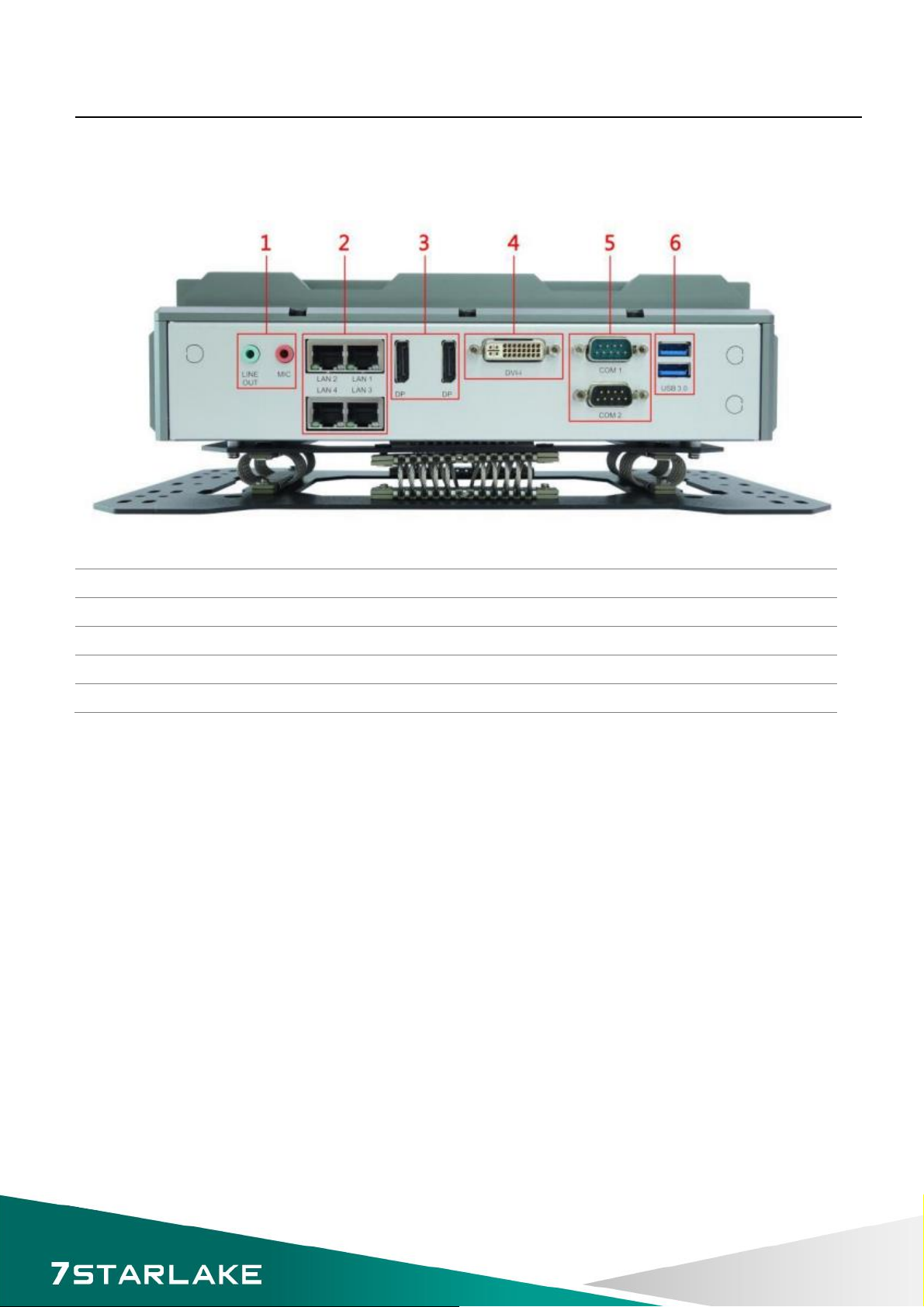
1.3 Back Panel Components
1
Audio Jack (1 x MIC, 1 x Line Out)
2
4 x RJ45 LAN Ports
3
2 x DisplayPort
4
1 x DVI-I
5
2 x DB ( 1 x RS232/422/485 with 5V/12V selectable, 1 x RS232)
6
2 x USB3.0 (Type A)

SR10B User’s Manual
Revision Date: Oct. 07. 2016
9
1.4 Mechanical Dimensions

SR10B User’s Manual
Revision Date: Oct. 07. 2016
10
Chapter 2: Jumpers and Connectors
This chapter describes the jumpers and connectors on the systems’ motherboard.
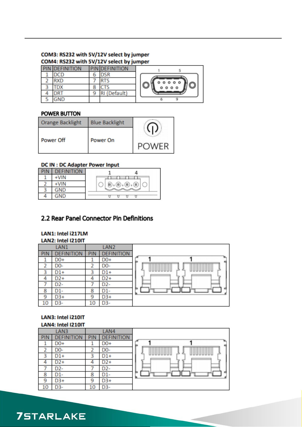
2.1 Front Panel Connector Pin Definitions
SR10B User’s Manual
Revision Date: Oct. 07. 2016
11

SR10B User’s Manual
Revision Date: Oct. 07. 2016
12

SR10B User’s Manual
Revision Date: Oct. 07. 2016
13
2.3 Internal Connector and Jumper Setting
SR10B User’s Manual
Revision Date: Oct. 07. 2016
14
Chapter 3: Installation
This chapter provide users the steps to install the HDD tray and vibration isolation base
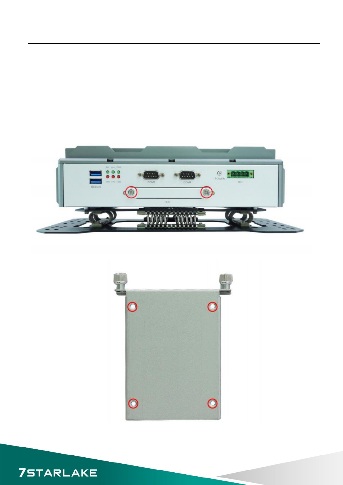
3.1 HDD tray
•Loosen the screws and pull out the 2.5” HDD tray.
•Pick 4 screws from the screw package.
•Put 2.5” HDD on the tray and use T9 torx driver to screw it up.
•Make sure HDD is fixed and push the tray back.3.2 Navigation Keys

SR10B User’s Manual
Revision Date: Oct. 07. 2016
15
3.3 Vibration Isolation Base
•Let the computer be upside down.
•Locate the vibration isolation base on the computer by the screw holes.
•Pick 6 screws from the screw package.
•Use Phillips screwdriver to screw it up.
SR10B User’s Manual
Revision Date: Oct. 07. 2016
16
Chapter 4: AMI BIOS UTILITY
This chapter provides users with detailed descriptions on how to set up a basic system configuration
through the AMI BIOS setup utility.
4.1 Starting
To enter the setup screens, perform the following steps:
•Turn on the computer and press the <Del> key immediately.
•After the <Del> key is pressed, the main BIOS setup menu displays. Other setup screens can be
accessed from the main BIOS setup menu, such as the Chipset and Power menus.
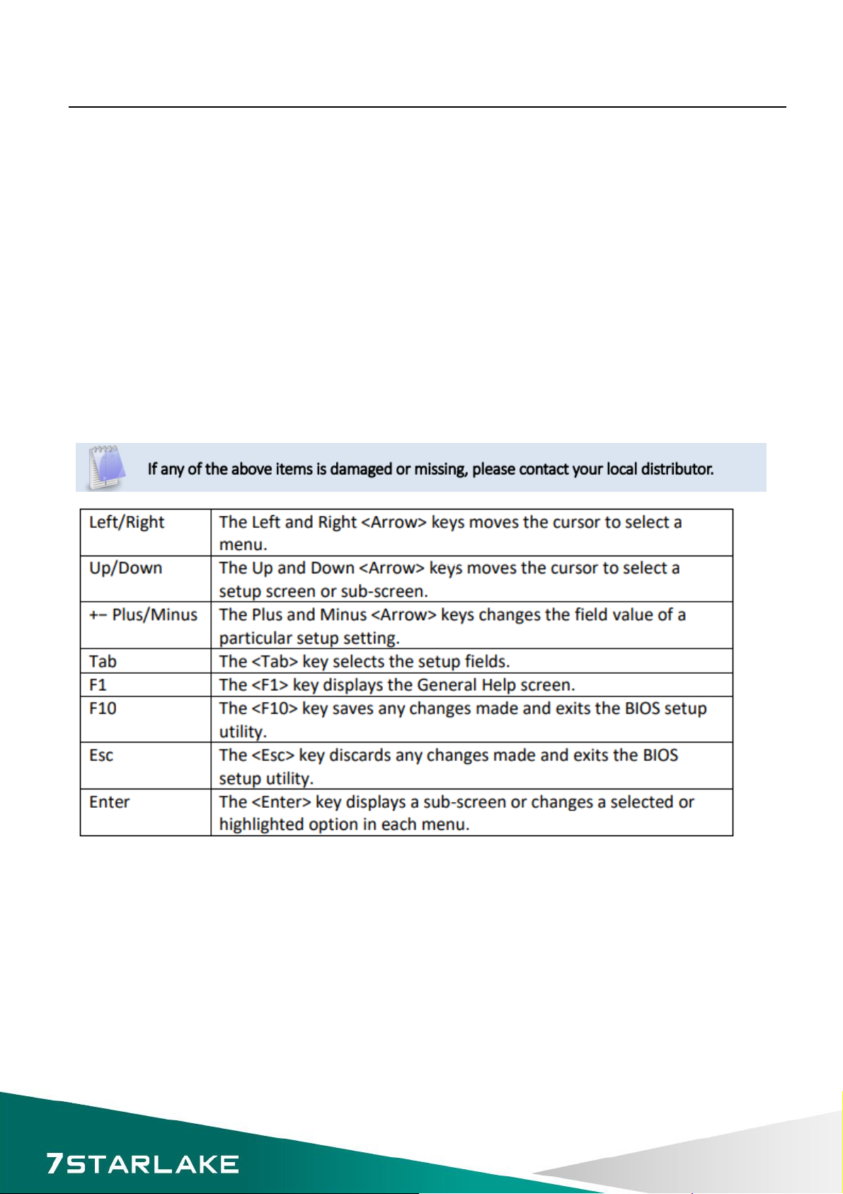
4.2 Navigation Keys
The BIOS setup/utility uses a key-based navigation system called hot keys. Most of the BIOS setup
utility hot keys can be used at any time during the setup navigation process.Some of the hot keys
are <F1>, <F10>, <Enter>, <ESC>, and <Arrow> keys.
SR10B User’s Manual
Revision Date: Oct. 07. 2016
17
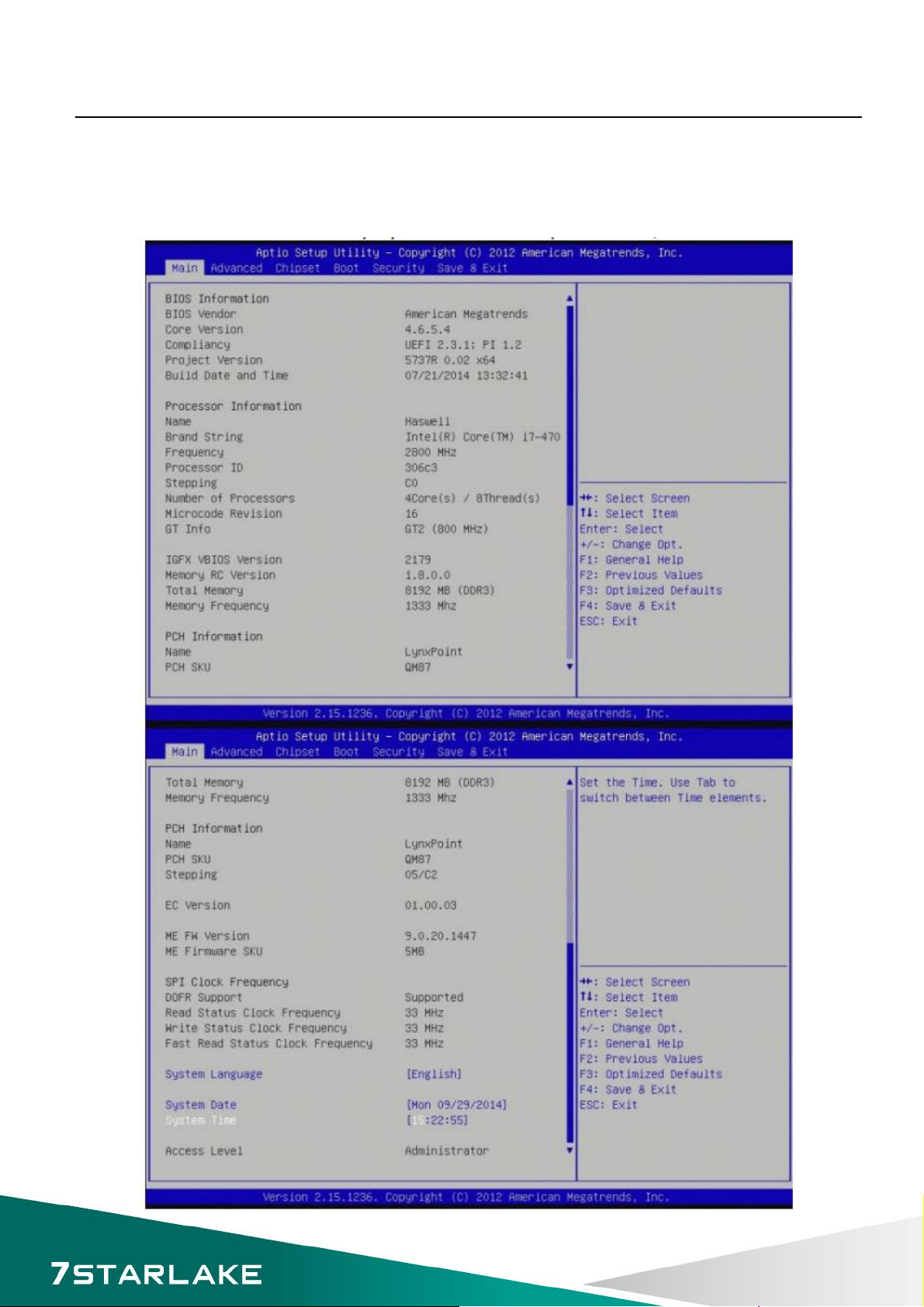
4.3 Main Menu
The Main menu is the screen that first displays when BIOS Setup is entered, unless an error has
occurred.

SR10B User’s Manual
Revision Date: Oct. 07. 2016
18
You could setup these items on the Main menu:
System Language: Choose the system default language.
System Date: Set the date. Use Tab to switch between date elements.
System Time: Set the time. Use Tab to switch between time elements.
Access Level
Displays the access level of the current user in the BIOS.
4.4 Advanced Menu
This section allows you to configure and improve your system and allows you to set up some system
features according to your preference.
SR10B User’s Manual
Revision Date: Oct. 07. 2016
19
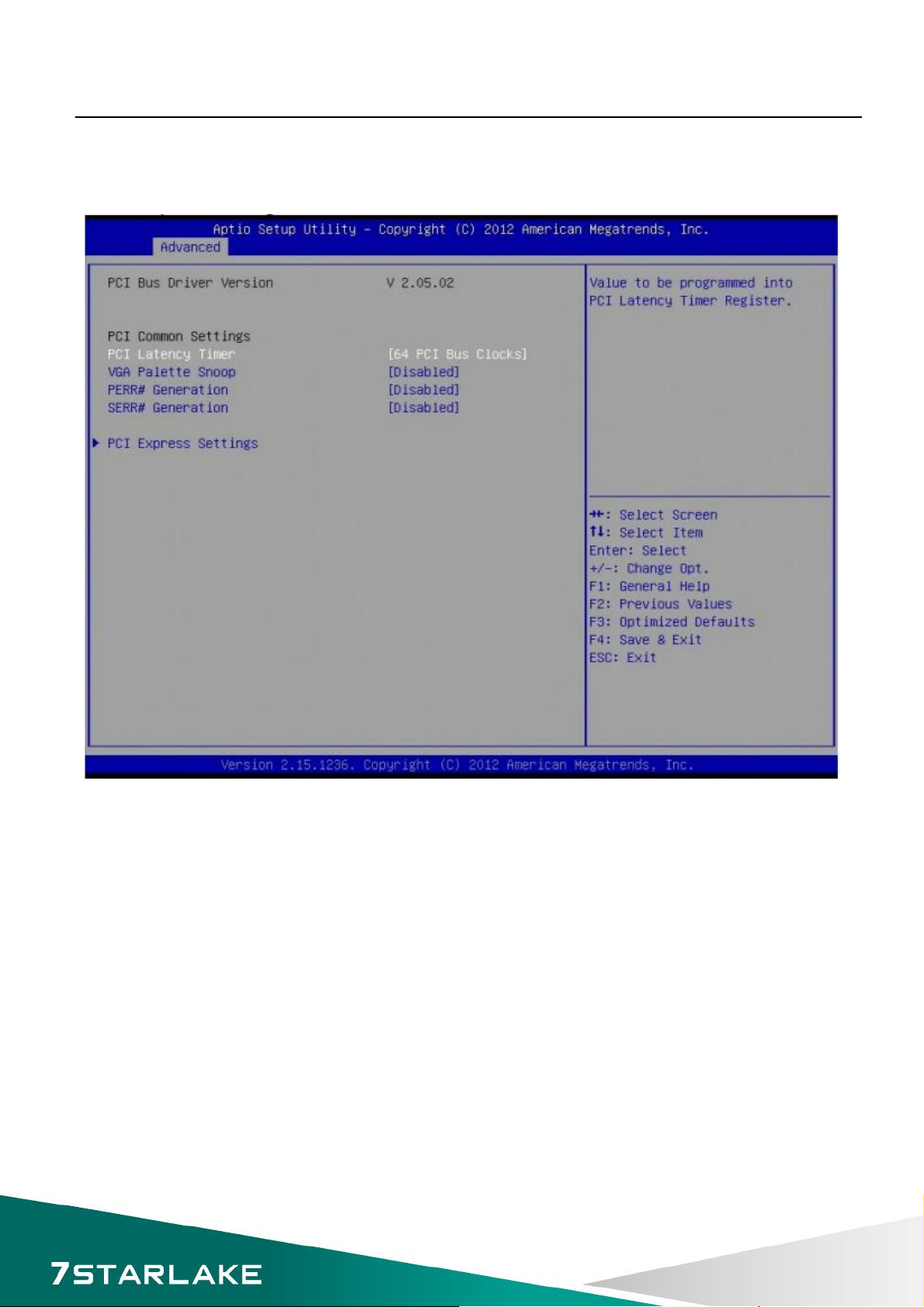
4.4.1 PCI Subsystem Settings
PCI, PCI-X and PCI Express settings.
PCI Common Settings
PCI Latency Timer: Value to be programed into PCI Latency Timer Register.
VGA Palette Snoop: Enable or disable VGA Palette Registers Snooping.
PERR# Generation: Enables or Disables PCI Device to Generate PERR#.
SERR# Generation: Enables or Disables PCI Device to Generate SERR#.
PCI Express Settings
Change PCI Express Devices Settings.
PCI Express Device Register Settings
Relaxed Ordering: Enables or Disables PCI Express Device Relaxed Ordering.
Extended Tag: If ENABLED allows Device to use 8-bit Tag field as a requester.
No Snoop: Enabled or Disables PCI Express Device No Snoop option.
Maximum Payload: Set Maximum Payload of PCI Express Device or allow System BIOS to select
the value.
Maximum Read Request: Set Maximum Read Request Size of PCI Express Device or allow System
Table of contents
Other Star Lake Desktop manuals

Star Lake
Star Lake SR700 User manual

Star Lake
Star Lake ROC286BB User manual

Star Lake
Star Lake SCH-406 User manual

Star Lake
Star Lake SR10-SCH User manual

Star Lake
Star Lake SCH-406 User manual

Star Lake
Star Lake THOR200-D15EG User manual

Star Lake
Star Lake AV710 User manual

Star Lake
Star Lake CPT330B User manual


