STAR Water Systems SW1369 User manual

1
Copyright © 2020. All rights reserved • 95 North Oak Street • Kendallville, IN 46755
POOL PUMP
Serial Number Purchase Date
Questions, problems, missing parts? Before returning to your retailer, call our customer service
department at 1-800-742-5044, 7:30 a.m. - 5:00 p.m., EST, Monday - Friday.
ATTACH YOUR RECEIPT HERE
IL2306
148014 1HP, 025191 1-1/2HP - SINGLE SPEED
DUAL VOLTAGE (115/230)
SW1369 B
Español p. 17

2 3
Copyright © 2020. All rights reserved • 95 North Oak Street • Kendallville, IN 46755Copyright © 2020. All rights reserved • 95 North Oak Street • Kendallville, IN 46755
PACKAGE CONTENTS
SAFETY INFORMATION
DESCRIPTION QUANTITY
APump 1
BAdapters
2” Slip Union 2
CAdapters
1.5” Slip Union 2
DCouplings 2
Basic safety precautions should always be followed, including the following. Failure to follow
instructions can cause severe injury and/or death.
This is the safety-alert symbol. When you see this symbol on your equipment or in this manual, look for
one of the following signal words and be alert to the potential for personal injury.
Warns about hazards that could cause serious personal injury, death or major property
damage and if ignored presents a potential hazard.
Warns about hazards that will or can cause minor or moderate personal injury and/or
property damage and if ignored presents a potential hazard. It can also make consumers
aware of actions that are unpredictable and unsafe.
The NOTICE label indicates special instructions that are important but not related to hazards.
READ AND FOLLOW ALL INSTRUCTIONS in this owner’s manual and on the
equipment. Failure to follow instructions can cause severe injury and/or death.
SUCTION ENTRAPMENT HAZARD. Suction inlets and outlets and/or suction outlet
covers which are damaged, broken, cracked, missing, or unsecured can cause severe
injury and/or death due to the following entrapment hazards:
• Hair Entrapment- Hair can become entangled in suction outlet cover.
• Limb Entrapment- A limb inserted into an opening of a suction outlet sump or suction outlet cover that is
damaged, broken, cracked, missing, or not securely attached can result in a mechanical bind or swelling of
the limb.
• Body Suction Entrapment- A negative pressure applied to a large portion of the body or limbs can result
in an entrapment.
• Evisceration/ Disembowelment - A negative pressure applied directly to the intestines through an
unprotected suction outlet sump or suction outlet cover which is, damaged, broken, cracked, missing, or
unsecured can result in evisceration/ disembowelment.
• Mechanical Entrapment- There is potential for jewelry, swimsuit, hair decorations, nger, toe or knuckle to
be caught in an opening of a suction outlet cover resulting in mechanical entrapment.
To Reduce the risk of Entrapment Hazards:
• When outlets are small enough to be blocked by a person, a minimum of two functioning suction outlets
per pump must be installed. Suction outlets in the same plane (i.e. oor or wall), must be installed a
minimum of three feet (3’) [1 meter] apart, as measured from near point to near point.
• Dual suction ttings shall be placed in such locations and distances to avoid “dual blockage” by a user.
• Dual suction ttings shall not be located on seating areas or on the backrest for such seating areas.
• The maximum system ow rate shall not exceed the ow rating as listed on Table 1.
• Never use pool or spa if any suction outlet component is damaged, broken, cracked, missing, or not
securely attached.
• Replace damaged, broken, cracked, missing, or not securely attached suction outlet components
immediately.
• Install two or more suction outlets per pump in accordance with latest ASME, APSP Standards and CPSC
guidelines. Follow all applicable National, State, and Local codes.
• Installation of a vacuum release or vent system, which relieves entrapping suction, is recommended.
Failure to remove pressure test plugs and/or plugs used in winterization of the pool/spa
from the suction outlets can result in an increase potential for suction entrapment as
described above.
Failure to keep suction outlet components clear of debris, such as leaves, dirt, hair, paper
and other material can result in an increased potential for suction entrapment as
described above.
Suction outlet components have a nite life. The cover/grate should be inspected
frequently and replaced at least every ten years or if found to be damaged, broken,
cracked, missing, or not securely attached.
Components such as the ltration system, pumps and heater must be positioned so as to
prevent their being used as means of access to the pool by young children.
Never operate or test the circulation system at more than 50 PSI.
Never change the lter control valve position while the pump is running.
To reduce risk of injury, do not permit children to use or climb on this product. Closely
supervise children at all times.
Hazardous Pressure. Pool and spa water circulation systems operate under hazardous
pressure during start up, normal operation, and after pump shut o. Stand clear of
circulation system equipment during pump start up. Failure to follow safety and operation instructions could
result in violent separation of the pump housing and cover, and/or lter housing and clamp due to pressure in
the system, which could cause property damage, severe personal injury, or death. Before servicing pool and
spa water circulation system, all system and pump controls must be in o position and lter manual air relief
valve must be in open position. Before starting system pump, all system valves must be set in a position to
allow system water to return back to the pool. Do not change lter control valve position while system pump is
running. Before starting system pump, fully open lter manual air relief valve. Do not close lter manual air
relief valve until a steady stream of water (not air or air and water) is discharged.
Separation Hazard. Failure to follow safety and operation instructions could result in
violent separation of pump and/or lter components. Strainer cover must be properly
secured to pump housing with strainer cover lock ring. Before servicing pool and spa circulation system, lter
manual air relief valve must be in open position. Do not operate pool and spa circulation system if a system
component is not assembled properly, damaged, or missing. Do not operate pool and spa circulation system
unless lter manual air relief valve body is in locked position in lter upper body.
IL2306
IL2322
IL2320
A
B
IL2319
CD
4 5
Copyright © 2020. All rights reserved • 95 North Oak Street • Kendallville, IN 46755Copyright © 2020. All rights reserved • 95 North Oak Street • Kendallville, IN 46755
Risk of Electric Shock. All electrical wiring MUST be in conformance with applicable
local codes, regulations, and the National Electric Code (NEC). Hazardous voltage can
shock, burn, and cause death or serious property damage. To reduce the risk of electric shock, do NOT use an
extension cord to connect unit to electric supply. Provide a properly located electrical receptacle. Before
working on any electrical equipment, turn o power supply to the equipment.
To reduce the risk of electric shock replace damaged wiring immediately. Locate conduit
to prevent contact from lawn mowers, hedge trimmers and other equipment.
Ground all electrical equipment before connecting to electrical power supply. Failure to
ground all electrical equipment can cause serious or fatal electrical shock hazard.
Do NOT ground to a gas supply line.
To avoid dangerous or fatal electrical shock, turn OFF power to all electrical equipment
before working on electrical connections.
Failure to bond all electrical equipment to pool structure will increase risk for electrocution
and could result in injury or death. To reduce the risk of electric shock, see installation
instructions and consult a professional electrician on how to bond all electrical equipment. Also, contact a
licensed electrician for information on local electrical codes for bonding requirements.
Notes to electrician: Use a solid copper conductor, size 8 or larger. Run a continuous wire from external
bonding lug to reinforcing rod or mesh. Connect a No. 8 AWG (8.4 mm2) [No. 6 AWG (13.3 mm2) for Canada]
solid copper bonding wire to the pressure wire connector provided on the electrical equipment and to all metal
parts of swimming pool, spa, or hot tub, and metal piping (except gas piping), and conduit within 5 ft. (1.5 m) of
inside walls of swimming pool, spa, or hot tub.
Reference NEC codes for all wiring standards including, but not limited to, grounding,
bonding and other general wiring procedures.
Risk of Electric Shock. Connect only to a branch circuit protected by a ground-fault
circuit-interrupter (GFCI). Contact a qualied electrician if you cannot verify that the circuit
is protected by a GFCI.
Risk of Electric Shock. The electrical equipment must be connected only to a supply
circuit that is protected by a ground-fault circuit-interrupter (GFCI). Such a GFCI should be
provided by the installer and should be tested on a routine basis. To test the GFCI, push the test button. The
GFCI should interrupt power. Push reset button. Power should be restored. If the GFCI fails to operate in this
manner, the GFCI is defective. If the GFCI interrupts power to the electrical equipment without the test button
being pushed, a ground current is owing, indicating the possibility of an electrical shock. Do not use this
electrical equipment. Disconnect the electrical equipment and have the problem corrected by a qualied
service representative before using.
This pump is intended for use with permanently-installed pools and may be used with hot
tubs and spas if so marked. Do not use with storable pools. A permanently-installed pool
is constructed in or on the ground or in a building such that it cannot be readily disassembled for storage. A
storable pool is constructed so that it is capable of being readily disassembled for storage and reassembled to
its original integrity.
MATERIALS NEEDED:
PVC Glue Tape Measure
Hack Saw Phillips Screwdriver
Flathead Screwdriver PTFE Pipe Thread Sealant Tape
Tongue and Groove Pliers Pipe Wrench
Round File or Sand Paper 2 in. Threaded Connections
(2 in. Slip Union & 1 1/2 in. Slip Union Included)
Shut O Valve On/O Timer
INTRODUCTION
This manual contains information for the proper installation and operation of the pool pump. The instructions in
this manual MUST be followed precisely. Failure to install according to dened instructions will void warranty.
PRODUCT BENEFITS
• See-through strainer cover lets you see when the basket needs cleaning.
• Heavy-duty, high performance motor for quieter, cooler operation.
• Service-ease design gives simple access to all internal parts.
• Handle for easy carrying and moving.
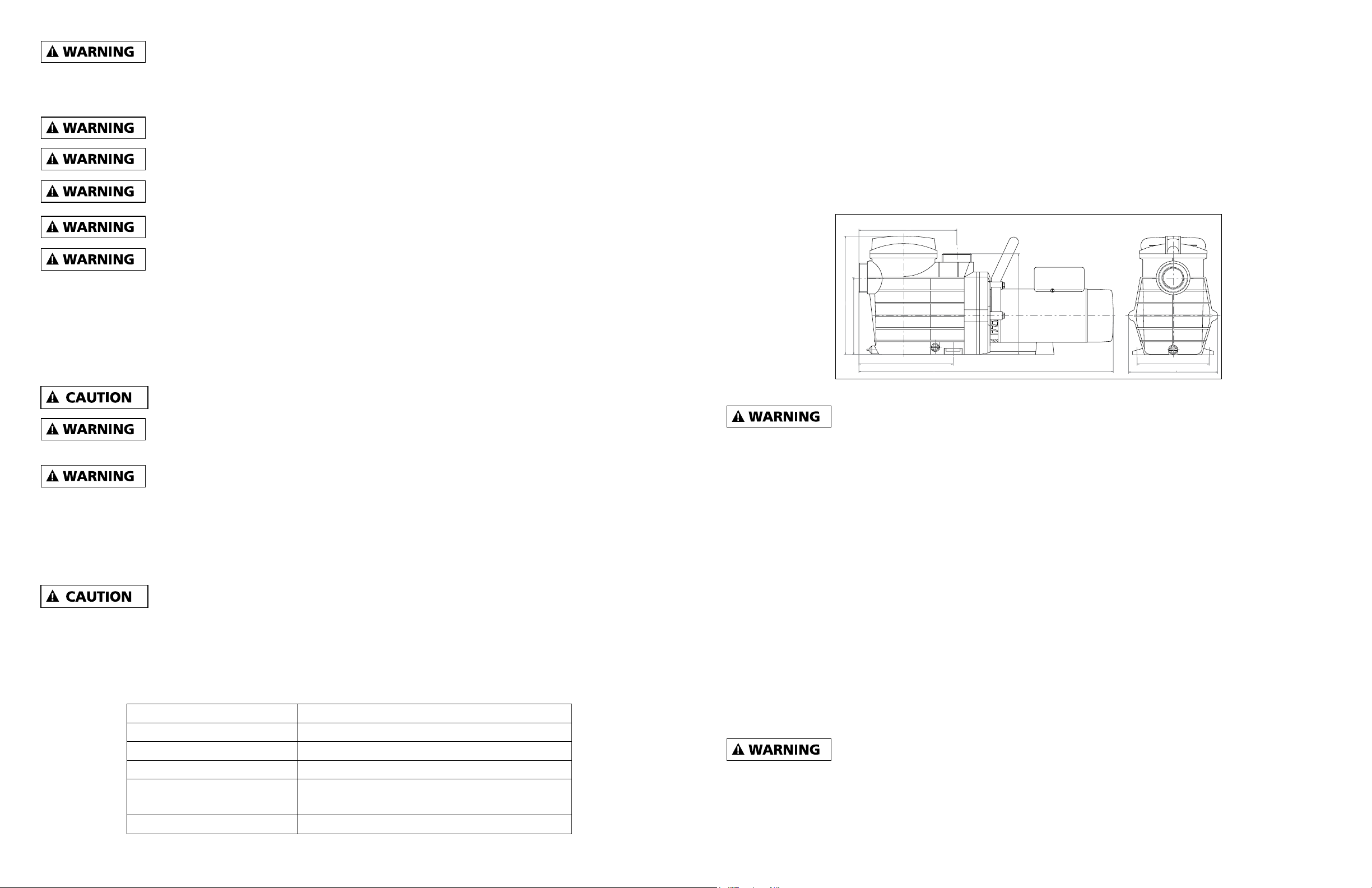
PRODUCT SPECIFICATIONS
10 in
10.4 in
8.1 in
12.6 in
10.7 in
7.6 in
9.5 in
Model 148014 16.6 in., Model 025191 25.6 in
This product should be installed and serviced only by a qualied professional.
PUMP LOCATION
Locate pump as close to pool as practical and run suction lines as direct as possible to reduce friction loss.
Suction line diameter must equal or be larger than the discharge line diameter. Suction lines should have
continuous slope upward from lowest point in line. Joints must be tight (but not over-tightened).
Though the pump is designed for outdoor use, it is strongly advised to protect the electrical components from
the weather. Select a well-drained area, one that will not ood when it rains. Do NOT install pump in a damp
or non-ventilated location. Keep motor clean. Pump motors require free circulation of air for cooling.
PUMP MOUNTING
Install pump on a rm, level base or pad to meet all local and national codes. Fasten pump to base or pad with
screws or bolts to further reduce vibration and stress on pipe or hose joints. The base MUST be solid, level,
rigid, and vibration free.
PUMP MOUNT MUST:
• Allow pump inlet height to be as close to water level as possible.
• Allow use of short, direct suction pipe (to reduce friction losses).
• Allow for gate valves in suction and discharge piping.
• Be protected from excess moisture and ooding.
• Allow adequate access for servicing pump and piping.
• Incorporate a straight portion of pipe prior to pump inlet no less than (5) pipe diameters in length.
Hazardous Pressure. Pumps, lters, and other equipment/components of a swimming
pool ltration system operate under pressure. Incorrectly installed and/or improperly
tested ltration equipment and/or components may fail resulting in injury and/or property damage.
67
Copyright © 2020. All rights reserved • 95 North Oak Street • Kendallville, IN 46755Copyright © 2020. All rights reserved • 95 North Oak Street • Kendallville, IN 46755
MAXIMUM RECOMMENDED SYSTEM FLOW RATE BY PIPE SIZE - TABLE 1
PIPE SIZE FLOW RATE WATER
VELOCITY PIPE SIZE FLOW RATE WATER
VELOCITY
Inches MM GPM Liter/
Min Ft/sec Meters/
sec Inches MM GPM Liter/
Min Ft/sec Meters/
sec
1-1/2 50 50.76 192 62.44 2.5” 75 119.40 452 8 2.44
2” 63 83.65 317 8 2.44 3” 90 184.32 698 8 2.44
NOTE – No system should allow any higher than 8-ft/sec (2.44 meters/sec) water velocity. It is recommended
that a minimum length of piping, equivalent to 10 pipe diameters, be used between the pump suction inlet and
any plumbing ttings.
PERFORMANCE
1. Find Your Pool Size
Use the formulas below to nd the capacity of your pool.
• Rectangular Pools: Length (ft.) x Width (ft.) x Average Depth (ft.) x 7.5 = Total pool capacity in gallons
• Circular Pools: Diameter (ft.) x Diameter (ft.) x Average Depth (ft.) x 5.9 = Total pool capacity in gallons
• Oval Pools: Length (ft.) x Width (ft.) x Average Depth (ft.) x 6.7 = Total pool capacity in gallons
Example for Rectangular Pool: 40 ft. L x 20 ft. W x 6 ft. average depth x 7.5 = 36,000 gallon capacity pool
2. Calculate Flow Rate, Gallons Per Minute (GPM) and Turnover
Pools should typically turn water over once every 8 hours. Use this ow rate formula along with your pool
capacity from step 1 to nd the Gallons Per Minute (GPM) you need for your system:
Pool Volume in Gallons ÷ Turnover Rate in Minutes = Flow Rate
Example: If you have a 30,000-gallon pool and you want the water to turn over once every eight hours:
30,000 ÷ 480 (60 minutes x 8 hours) = 62.5 GPM
Your 30,000-gallon pool needs 62.5 gallons per minute to circulate the water once every eight hours.
3. Calculate Maximum Flow Rate
This number helps you match the pump with your pool lter. Your pool lter has a maximum ow rate, which
is measured in GPM. The GPM rating of the pump should be less than the GPM rating of the pool lter. If the
pump is rated higher than the lter, the lter is undersized and will not work properly.
The size of your pool pipes determines the maximum ow rate for your system.
Count the number of intake lines for your pool and reference the pipe sizes below:
• For each 1.5-inch intake line, the maximum ow rate is 42 GPM.
• For each 2-inch intake line, the maximum ow rate is 73 GPM.
Example: Two 1.5-inch intake lines = 84. The maximum ow rate is 84 GPM.
4. Calculate Resistance
Every piece of equipment in the pump system creates resistance to water ow. Pipe length and size, type of
lter, heaters and pool cleaners all add to this resistance.
The easiest way to nd resistance is to use a pressure meter and these formulas:
• Check the pressure of water owing into the lter tank and multiply that number by 2.31.
• Check the vacuum reading on the pump suction line and multiply that by 1.13.
• Add the two numbers together to nd is the resistance, or total dynamic head.
Example: If the water owing into the lter tank is 15 PSI, and the vacuum reading on the pump suction line
is 6 PSI:
Water ow into lter tank: 15 PSI x 2.31 = 34.65
Vacuum reading on pump suction line: 6 PSI x 1.13 = 6.78
Total = 41.43 ft. of resistance or TDH
Use the chart below to determine expected gallons per minute for your installation.
PLUMBING
Use Teon tape to seal threaded connections on molded plastic components. All plastic ttings must be new
or thoroughly cleaned before use. NOTE - Do NOT use Plumber’s Pipe Dope as it may cause cracking
of the plastic components. When applying Teon tape to plastic threads, wrap the entire threaded portion
of the male tting with one to two layers of tape. Wind the tape clockwise as you face the open end of the
tting, beginning at the end of the tting. The pump suction and outlet ports have molded-in thread stops. Do
NOT attempt to force hose connector tting past this stop. It is only necessary to tighten ttings enough
to prevent leakage. Tighten tting by hand and then use a tool to engage tting an additional 1-1/2 turns. Use
care when using Teon tape as friction is reduced considerably; do NOT over-tighten tting or you may
cause damage. If leaks occur, remove connector, clean o old Teon tape, re-wrap with one to two additional
layers of Teon tape, and re-install connector.
FITTINGS
Fittings restrict ow. For better eciency, use the fewest possible ttings (but at least two suction outlets).
Avoid ttings that could cause an air trap. Pool and spa ttings MUST conform to the International Association
of Plumbing and Mechanical Ocials (IAPMO) standards. Use a non-entrapping suction tting in pool (multiple
drains) or double suction (skimmer and main drain).
SPECIFICATIONS
MODEL HP PERFORMANCE IN GALLONS PER MINUTE
20’ TDH 30’ TDH 40’ TDH 50’ TDH 60’ TDH 70’ TDH
148014 1 90 80 64 43 16 -
025191 1-1/2 110 100 90 79 62 47

8 9
Copyright © 2020. All rights reserved • 95 North Oak Street • Kendallville, IN 46755Copyright © 2020. All rights reserved • 95 North Oak Street • Kendallville, IN 46755
Fuse Box
5
Fuse Box
Fill Level
6
Return Line
Filter Outlet
Return Line
Goes to Pool Jets
IL2562
4
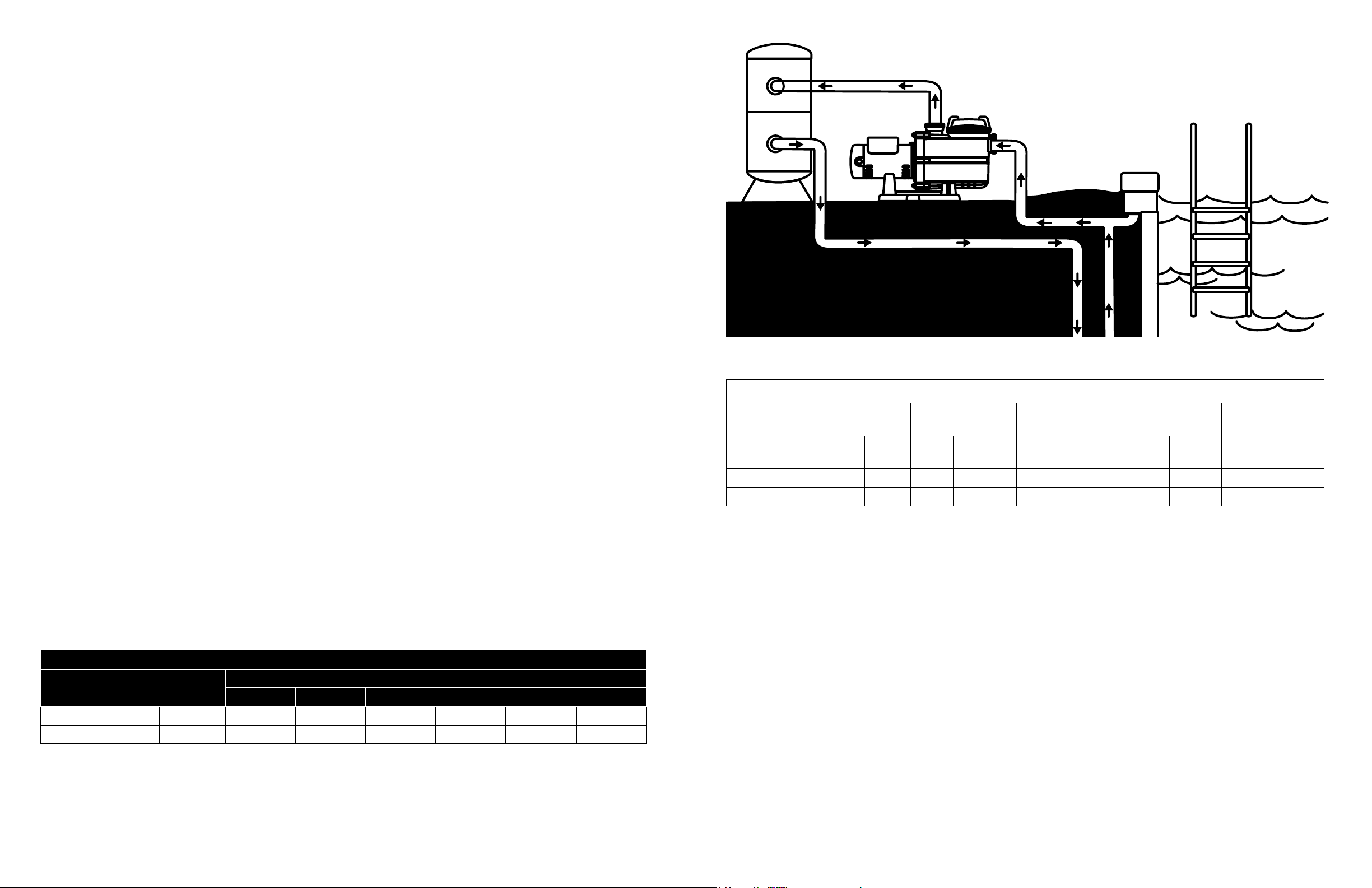
4. Connect return line from lter to swimming pool
return inlet.
6. Fill pump and trap with water, replace trap lid
and check system for leaks. If no leaks, proceed
with pump startup.
NOTE: DO NOT START PUMP if any leaks are
present in the system.
After startup check again for leaks again at
each connection.
5. Make sure power is o and attach wiring.
Always disconnect
pump from electricity
before performing any work on the motor.
Refer to instructions for wiring connections.
INSTALLATION:INSTALLATION:
IL2562
Pump inlet
1
IL2562
Shut Off
Valve
Pump
Inlet Pipe
Pool
Skimmer
Pipe Union
2
Shut Off
Valve
Pump Discharge Line
Filter Inlet
Pipe Union
IL2562
3
NOTE: Before installing the pump check your
voltage requirements. The pump is preset to
230V. If your power source is 115V see page 10
and follow instructions to change wiring according
to the diagrams.
1. Install pump on a rm, level base or pad with
screws or bolts. The base MUST be solid, level,
rigid, vibration free and protected from both
weather and pool splash. Make sure pump inlet
height is as close to the water level as possible.
2. Attach discharge line from pump to lter inlet
using a pipe union and attach shut-o valve.
Use a short and direct suction pipe. Be sure to
incorporate a straight portion of pipe that is at
least 5 times longer than the diameter of the
pump inlet pipe.
3. Use a pipe union to attach discharge line from
pump to lter inlet and attach shut-o valve.
Suction line pipe must the same diameter or
larger than the discharge line.
10 11
Copyright © 2020. All rights reserved • 95 North Oak Street • Kendallville, IN 46755Copyright © 2020. All rights reserved • 95 North Oak Street • Kendallville, IN 46755
VOLTAGE
Voltage at motor MUST NOT be more than 10% above or below motor name plate rated voltage, or motor may
overheat, causing overload tripping and reduced component life. If voltage is less than 90% or more than 110%
of rated voltage when motor is running at full load, consult power company.
GROUNDING AND BONDING
• Install, ground, bond, and wire motor in accordance with local or national electrical code requirements.
• Permanently ground motor. Use green ground terminal provided under motor canopy or access place; use
size and type wire required by code. Connect motor ground terminal to electrical service ground.
• Bond motor to pool structure. Bonding will connect all metal parts within and around the pool with a
continuous wire. Bonding reduces the risk of a current passing between bonded metal objects, which could
potentially cause electrical shock if grounded or shorted. Reference NEC codes for all wiring standards
including, but not limited to, grounding, bonding and general wiring procedures.
• Use a solid copper conductor, per code. Run wire from external bonding lug to reinforcing rod or mesh.
Connect per code solid copper bonding wire to the pressure wire connector provided on the motor housing
and to all metal parts of swimming pool, spa, or hot tub, and to all electrical equipment, metal piping
(except gas piping), and conduit within 5 ft. (1.5 m) of inside walls of swimming pool, spa, or hot tub.
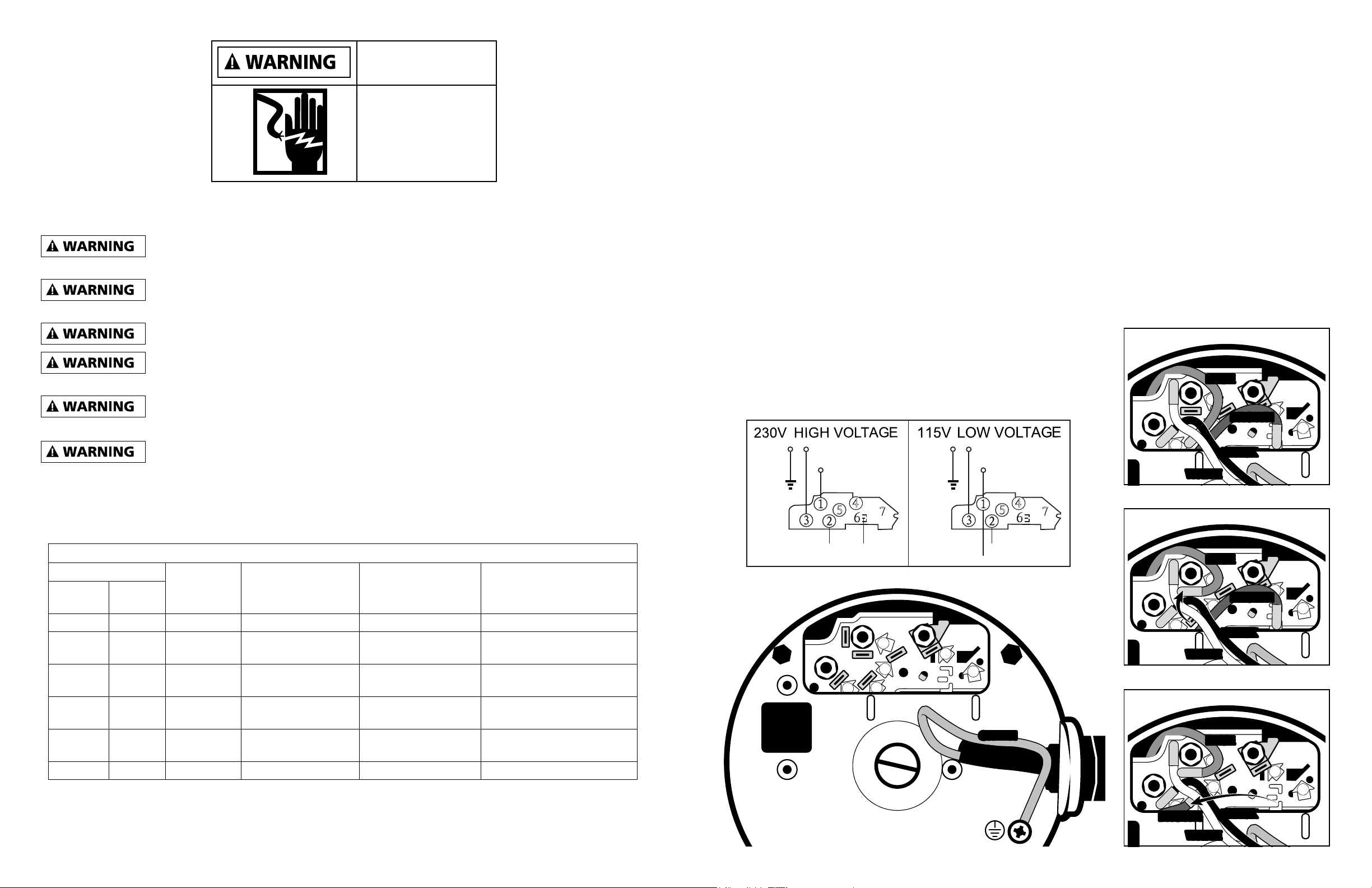
CHANGING THE VOLTAGE
• Pump is preset to 230V. If your power source is 115V, open the
back of the motor housing. Use pliers to switch plugs following the
steps to the right in order to match the 115V diagram below.
• While set for 230V the brown wire may still have current. It must
stay grounded in position 6 to avoid touching other contacts.
1
32
5
4
67
GREENGREEN
1
32
5
4
67
BROWNBROWN
BLACK
BLACK
BLUE
BLUE
WHITE
WHITE
1
32
5
4
67
BLACKBLACK
BLUE
BLUE
BROWN
BROWN
WHITE
WHITE
1
32
5
4
67
BLACKBLACK
WHITE
WHITE
BROWN
BROWN
BLUE
BLUE
4
57
4
57
Blue
White
Black
Green
(LINE)
(LINE)
BrownBlue
White
Black
Green
(LINE)
(LINE)
Brown
Single Speed
STEP 1
STEP 2
STEP 3
Default 230V wire positions.
Move blue wire from slot 2 to slot 1
Move brown wire from position 6 to slot 2
Hazardous voltage. Can
shock, burn, or cause
death.
BEFORE WORKING
ON PUMP OR
MOTOR:
Unplug pump motor.
ELECTRICAL
All wiring must be done by a licensed electrician and must conform to all local and
national codes and regulations.
Ground and bond motor before connecting to electrical power supply. Failure to ground
and bond pump motor can cause serious or fatal electrical shock hazard.
Do NOT ground to a gas supply line.
To avoid dangerous or fatal electrical shock, turn OFF power to motor before working on
electrical connections.
Ground Fault Circuit Interrupter (GFCI) tripping indicates electrical problem. If GFCI trips
and won’t reset, consult electrician to inspect and repair electrical system.
Fire Hazard. Match supply voltage to motor nameplate voltage.
Ensure that the electrical supply available agrees with the motor’s voltage, phase, and cycle, and that the wire
size is adequate for the HP (kW) rating and distance from the power source. NOTE - All electrical wiring
MUST be performed by a licensed electrician, and MUST conform to local codes and NEC regulations.
Use copper conductors only.
ELECTRICAL GUIDE - 60 CYCLE - SINGLE PHASE
MOTOR
VOLTS
CIRCUIT
BREAKER
RATINGS-AMPS
BRANCH
FUSETRON
RATINGS-AMPS
RECOMMENDED
WIRE SIZE 0-50’
KW HP
.37 1/2 115 15 15 No. 14
.55 3/4 115
230
15
10
15
6.25 No. 14
.75 1 115
230
20
10
20
9
No. 12
No. 14
1.1 1 1/2 115
230
30
15
30
15
No. 10
No. 14
1.55 2 115
230
30
15
30
12
No. 10
No. 14
1.88 2 1/2 230 20 20 No. 12

12 13
Copyright © 2020. All rights reserved • 95 North Oak Street • Kendallville, IN 46755Copyright © 2020. All rights reserved • 95 North Oak Street • Kendallville, IN 46755
MAINTENANCE
• Clean strainer basket regularly. Do NOT strike basket to clean. Inspect strainer cover gasket regularly and
replace as necessary.
• Pump has self-lubricating motor bearings and shaft seals. No lubrication is necessary.
• Keep motor clean. Ensure air vents are free from obstruction to avoid damage. Do NOT use water to hose
o motor.
• Occasionally, shaft seals must be replaced, due to wear or damage.
Separation Hazard. Do not purge the system with compressed air. Purging the system
with compressed air can cause components to explode, with risk of severe injury or death
to anyone nearby. Use only a low pressure (below 5 PSI), high volume blower when air purging the pump,
lter, or piping.
Allowing the pump to freeze will void the warranty.
Use ONLY propylene glycol as antifreeze in your pool/spa system. Propylene glycol is
non-toxic and will not damage plastic system components. Other anti-freezes are highly
toxic and may damage plastic components in the system.
Drain all water from pump and piping when expecting freezing temperatures or when storing pump for a long
time (see instructions below).
Keep motor dry and covered during storage. To avoid condensation/corrosion problems, do NOT cover or wrap
pump with plastic lm or bags.
STORING PUMP FOR WINTERIZATION
To avoid dangerous or fatal electrical shock hazard, turn OFF power to
motor before draining pump. Failure to disconnect power may result in
serious personal injury or death.
1. Drain water level below all inlets to the pool.
2. Remove drain plugs from bottom of strainer body, and remove strainer cover from
strainer housing.
3. Disconnect pump from mounting pad, wiring system (after power has been turned OFF),
and piping system.
4. Once the water is emptied from the pump, re-install the strainer cover and drain plugs. Store pump in a dry
area.
WIRING
A licensed electrician must do all wiring.
Pump MUST be permanently connected to circuit. If other lights or appliances are also on the same circuit, be
sure to add their amp loads before calculating wire and circuit breaker sizes. Use the load circuit breaker as
the Master On-O switch.
Install a Ground Fault Circuit Interrupter (GFCI) in circuit; it will sense a short-circuit to ground and disconnect
power before it becomes dangerous to pool users. For size of GFCI required and test procedures for GFCI,
see manufacturer’s instructions. Pump MUST be permanently connected to GFCI. In case of a power outage,
check GFCI for tripping, which will prevent normal pump operation. Reset if necessary.
All suction and discharge valves MUST be OPEN, as well as lter air relief valve (if
available) on lter, when starting the circulating pump system. Failure to do so could result
in severe personal injury.
STARTING/PRIMING THE PUMP:
Pumps with single speed motors are self priming to 10 ft. and pumps with 2 speed motors are self priming to
10 ft. on high speed only. Fill strainer housing with water to suction pipe level. If water leakage occurs from
anywhere on the pump or lter, DO NOT start the pump. If no leakage occurs, stand at least 10 feet from pump
and/or lter and proceed with starting the pump.
Return to lter to close lter manual air relief valve when a steady stream of water (not air
or air and water) is discharged from valve. Failure to do so could result in severe personal
injury.
NEVER OPERATE THE PUMP WITHOUT WATER. Water acts as a coolant and
lubricant for the mechanical shaft seal. NEVER run pump dry. Running pump dry may
damage seals, causing leakage, ooding, and voids warranty. Fill strainer housing with water before starting
motor.
Do NOT add chemicals to pool/spa system directly in front of pump suction. Adding
undiluted chemicals may damage pump and voids warranty.
Before removing strainer cover:
1. STOP PUMP before proceeding.
2. CLOSE VALVES in suction and outlet pipes.
3. RELEASE ALL PRESSURE from pump and piping system using lter manual air relief valve. See lter
owner’s manual for more details.
4. If water source is higher than the pump, pump will prime itself when suction and outlet valves are opened.
If water source is lower than the pump, unscrew and remove strainer cover; ll strainer housing with water.
5. Clean and lubricate strainer cover O-ring with silicone lubricant each time it is removed. Inspect O-ring and
re-install on strainer cover.
6. Replace strainer cover on strainer housing; turn strainer cover clockwise to tighten cover.
Before re-starting pump, see “Starting/Priming the Pump” instructions.
Wait ve (5) seconds before re-starting pump. Failure to do so may cause reverse
rotation of motor and consequent serious pump damage.
Turn on power and wait for pump to prime, which may take up to ve (5) minutes. Priming time will depend on
vertical length of suction lift and horizontal length of suction pipe. If pump does NOT prime within ve minutes,
stop motor and determine cause. Be sure all suction and discharge valves are open when pump is running.
See Troubleshooting Guide.
14 15
Copyright © 2020. All rights reserved • 95 North Oak Street • Kendallville, IN 46755Copyright © 2020. All rights reserved • 95 North Oak Street • Kendallville, IN 46755
PROBLEM CHECK FOR: SOLUTION
A. Motor Will NOT
Start
Improper or loose wiring connections;
open switches or relays; tripped circuit
breakers, GFCI’s, or blown fuses.
Check all connections, circuit breakers,
and fuses. Reset tripped breakers or
replace blown fuses
Check rotation of motor shaft Remove any obstructions.
Properly working timer. Bypass timer if necessary.
B. Motor Shuts OFF
Low voltage at motor or power drop
(frequently caused by undersized wiring
or extension cord use.)
Contact qualied professional to check
that the wiring gauge is heavy enough.
**NOTE: Your motor is equipped with an “automatic thermal overload protector.” The motor will automatically
shut o if power supply drops before heat damage can build up causing windings to burn out. The “thermal
overload protector” will allow the motor to automatically restart once the motor has cooled. It will continue to
cut On/O until the problem is corrected. Be sure to correct cause of overheating.
C. Motor Hums, But
Does NOT Start
Impeller jammed with debris. Have a qualied repair professional open
the pump and remove the debris.
D. Pump Won’t Prime
Empty pump/strainer housing. Make sure pump/strainer housing is lled
with water and cover O-Ring is clean.
Ensure O-Ring is properly seated in the
cover O-Ring groove. Ensure O-Ring
is lubricated and that strainer cover is
locked rmly in position.
Loose connections on suction side. Tighten pipe/union connections.
Leaking O-Ring or packing glands on
valves. Strainer basket or skimmer
loaded with debris.
Remove strainer housing cover or
skimmer cover, clean basket, and rell
strainer housing with water. Tighten
cover.
Suction side clogged. Contact a qualied repair professional.
Block o to determine if pump will develop a vacuum. You should have 5”-6” of vacuum at the strainer cover
(Only your pool dealer can conrm this with a vacuum gauge). You may be able to check by removing
the skimmer basket and holding your hand over the bottom port with skimmer full and pump running. If no
suction is felt, check for line blockage.
a. If pump develops a vacuum, check for blocked suction line or dirty strainer basket. An air leak in the
suction piping may be the cause.
b. If pump does not develop a vacuum and pump has sucient “priming water”:
i. Re-check strainer housing cover and all threaded connections for suction leaks. Check if all
system hose clamps are tight.
ii. Check voltage to ensure that the motor is rotating at full RPM’s.
iii. Open housing cover and check for clogging or obstruction in suction. Check impeller for debris.
iv. Remove and replace shaft seal only if it is leaking.
PROBLEM CHECK FOR: SOLUTION
E. Low Flow
Clogged or restricted strainer or suction line.
Contact a qualied repair professional.
Undersized pool piping. Correct piping size.
Plugged or restricted discharge line of lter,
valve partially closed (high gauge reading).
Sand lters - backwash as per
manufacturer’s instructions; D.E. lters -
backwash as per manufacturer’s instructions;
Cartridge lters - Clean or replace cartridge.
Air leak in suction (bubbles issuing from
return ttings).
Re-tighten using Teon tape.
Plugged, restricted, or damaged impeller. Replace, including new seal assembly.
F. Noisy Pump
1. Air leak in suction piping, cavitations
caused by restricted or undersized
suction line or leak at any joint, low
water level in pool, and unrestricted
discharge return lines.
1. Correct suction condition or throttle return
lines, if practical. Holding hand over tting
will sometimes prove this point or putting
in a smaller eyeball tting.
2. Vibration due to improper mounting, etc.
2. Replace mounting.
3. Foreign matter in pump housing. Loose
stones/debris hitting impeller could be
cause.
3. Clean the pump housing.
4. Motor bearings noisy from normal wear,
rust, overheating, or concentration of
chemicals causing seal damage which
will allow chlorinated water to seep into
bearings wiping out the grease causing
bearing to whine.
4. All seal leaks should be replaced at once.
TROUBLESHOOTING TROUBLESHOOTING
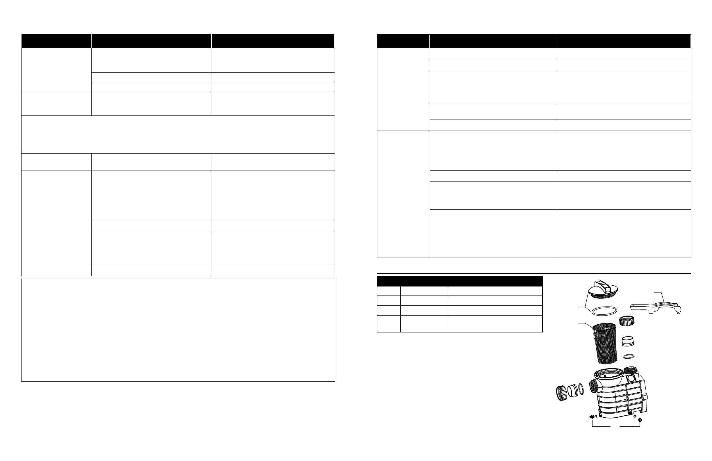
REPAIR PARTS
ITEM P/N DESCRIPTION
A025467 Cover with O-Ring
B025466 Filter/Strainer Basket
C025465 Drainage Plug with O-ring
D025468 Spanner - Tool for Opening the
Transparent Cover
A
B
C
D
IL2594

16
Copyright © 2020. All rights reserved • 95 North Oak Street • Kendallville, IN 46755
WARRANTY
This product is warranted for one year from the date of purchase. Subject to the conditions hereinafter
set forth, the manufacturer will repair or replace to the original consumer, any portion of the product
which proves defective due to defective materials or workmanship. This warranty does not cover
replacement parts for failure due to normal wear and tear. To obtain warranty service, contact the
dealer from whom the product was purchased. The manufacturer retains the sole right and option to
determine whether to repair or replace defective equipment, parts or components. Damage due to
conditions beyond the control of the manufacturer is not covered by this warranty.
THIS WARRANTY WILL NOT APPLY:
(a) To defects or malfunctions resulting from failure to properly install, operate or maintain the unit in
accordance with printed instructions provided;
(b) to failures resulting from abuse, accident or negligence or use of inappropriate chemicals or
additives in the water;
(c) to normal maintenance services and the parts used in connection with such service;
(d) to units which are not installed in accordance with normal applicable local codes, ordinances and
good trade practices; and
(e) if the unit is used for purposes other than for what it was designed and manufactured.
RETURN OF WARRANTED COMPONENTS: Any item to be repaired or replaced under this warranty
must be returned to the manufacturer at Kendallville, Indiana or such other place as the manufacturer
may designate, freight prepaid.
THE WARRANTY PROVIDED HEREIN IS IN LIEU OF ALL OTHER EXPRESS WARRANTIES, AND MAY
NOT BE EXTENDED OR MODIFIED BY ANYONE. ANY IMPLIED WARRANTIES SHALL BE LIMITED TO
THE PERIOD OF THE LIMITED WARRANTY AND THEREAFTER ALL SUCH IMPLIED WARRANTIES ARE
DISCLAIMED AND EXCLUDED. THE MANUFACTURER SHALL NOT, UNDER ANY CIRCUMSTANCES, BE
LIABLE FOR INCIDENTAL, CONSEQUENTIAL OR SPECIAL DAMAGES, SUCH AS, BUT NOT LIMITED TO
DAMAGE TO, OR LOSS OF, OTHER PROPERTY OR EQUIPMENT, LOSS OF PROFITS, INCONVENIENCE,
OR OTHER INCIDENTAL OR CONSEQUENTIAL DAMAGES OF ANY TYPE OR NATURE. THE LIABILITY
OF THE MANUFACTURER SHALL NOT EXCEED THE PRICE OF THE PRODUCT UPON WHICH SUCH
LIABILITY IS BASED.
This warranty gives you specic legal rights, and you may have other rights which vary from state to
state. Some states do not allow limitations on duration of implied warranties or exclusion of incidental
or consequential damages, so the above limitations may not apply to you.
In those instances where damages are incurred as a result of an alleged pump failure, the
Homeowner must retain possession of the pump for investigation purposes.
This manual suits for next models
1
Table of contents
Other STAR Water Systems Swimming Pool Pump manuals


