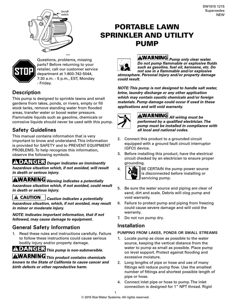
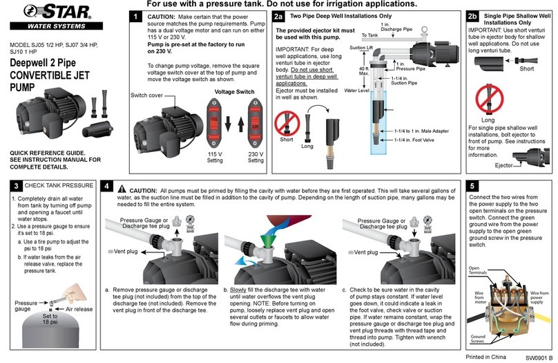
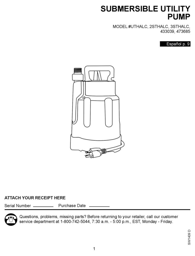
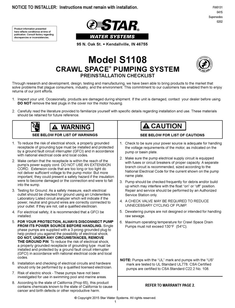
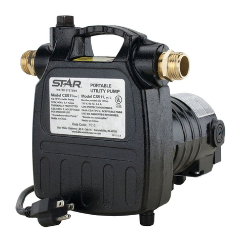
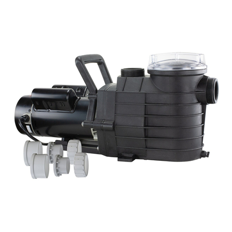
Star STL001 User manual

1
© 2019. All rights reserved.
Serial Number Purchase Date
Questions, problems, missing parts? Before returning to your retailer, call our customer
service department at 1-800-584-8089, 7:30 a.m. - 5:00 p.m., EST, Monday - Friday.
ATTACH YOUR RECEIPT HERE
UTILITY/LAUNDRY
SINK PUMP
MODEL #STL001
Español p. 11
SW1399 A

2
© 2019. All rights reserved.
PACKAGE CONTENTS
SAFETY INFORMATION
ITEM DESCRIPTION QUANTITY
A Pump 1
B Ball Valve 1
C Check Valve 1
D Strainer 1
Please read and understand this entire manual before attempting to assemble, operate or install the
product.
NOTE: Pumps with the “UL” Mark and pumps with the “US” mark are tested to UL Standard UL778.
CSA certied pumps are certied to CSA Standard C22.2 No. 108. (CUS.)
IMPORTANT
• The motor of this pump has a thermal protector that will trip if the motor becomes too hot. The
protector will reset itself once the motor cools down and an acceptable temperature has been
reached. The pump may start unexpectedly if it is plugged in.
• Ensure the electrical power source is adequate for the requirements of the pump.
• This pump is made of high-strength, corrosion-resistant materials. It will provide trouble-free
service for a long time when properly installed, maintained, and used. However, inadequate
electrical power to the pump, dirt, or debris may cause the pump to fail. Please carefully read the
manual and follow the instructions regarding common pump problems and remedies.
NOTE: This pump does not require a connection to a main stack vent, per the National Standard
Plumbing Code (NSPC) 2003 Section 11.7.9.

3
© 2019. All rights reserved.
WARNING
• Extension cords may not deliver sufficient voltage to the pump motor. Extension cords present a
life threatening hazard if the insulation becomes damaged or the connection ends fall into water.
The use of an extension cord to power this pump is not permitted.
• Secure the discharge line before starting the pump. An unsecured discharge line will whip,
possibly causing personal injury, and/or property damage.
• Ensure that the electrical circuit to the pump is protected by a 15 amp fuse or circuit breaker.
• Release all pressure and drain all water from the system before servicing any component.
• Wear safety goggles at all times when working with pumps.
• The unit is designed only for use on 115 volts (single phase), 60 Hz, and is equipped with an
approved 3-conductor cord and 3-prong grounded plug. Do not remove the ground pin under any
circumstances. The 3-prong plug must be directly inserted into a properly installed and grounded
3-prong, grounding-type receptacle. Do not use this pump with a 2-prong wall outlet. Replace the
2-prong outlet with a properly grounded 3-prong receptacle (a GFCI outlet) installed in accordance
with the National Electrical Code and local codes and ordinances. All wiring should be performed
by a qualified electrician.
• Protect the electrical cord from sharp objects, hot surfaces, oil, and chemicals. Avoid kinking the
cord. Do not use damaged or worn cords.
DANGER
• Do not pump flammable or explosive liquids such as oil, gasoline, kerosene, ethanol, etc. Do not
use in the presence of flammable or explosive vapors. Using this pump with or near flammable
liquids can cause an explosion or fire, resulting in property damage, serious personal injury, and/
or death.
• Always disconnect the power to the pump before servicing.
• Do not touch the motor housing during operation. The motor is designed to operate at high
temperatures. Do not disassemble the motor housing.
• Do not handle the pump or pump motor with wet hands or when standing on a wet surface, or in
water.
CAUTION
• Do not lift the pump by the power cord.
• Know the pump and its applications, limitations, and potential hazards.
• Follow all safety standards and all local electrical codes.
SPECIFICATIONS
Power Supply 115V, 60Hz., 15 Amp Circuit
Liquid Temp Range 32°F to 120°F (0°-50°C)
Pump Inlet 1-1/2 in. NPT
Pump Discharge 1-1/4 in. NPT

4
© 2019. All rights reserved.
PREPARATION
Materials required for assembly:
11-1/2” NPT x 1-1/2” Slip Female Adapter
2 1-1/2” Schedule 40 PVC Pipe (to fit)
31-1/2” NPT x 1-1/2” Slip Male Adapter
41-1/4” NPT Galvanized Nipple (to fit)
51-1/4” NPT Galvanized Union
6 (2) 1-1/4” NPT x1-1/4” Male Adapter
7(2) 1-1/4” Schedule 40 PVC Pipe (to fit)
81-1/4” Socket to Socket 90° Elbow
9 1-1/4” Schedule 40 PVC Pipe to Drain
PVC Pipe Cement
PTFE Pipe Thread Sealant Tape
1-1/2” PVC Solvent Union
Materials supplied: Sink Drain Screen (D), 1-1/4” NPT x 1-1/4” Slip Check Valve (C),
1-1/4” NPT Ball Valve (B)
Sink Bottom with Drain Port;
Tail Piece integral with Sink
1-1/2” Pump
Inlet Port
1-1/4” Pump
Discharge
For easier maintenance,
use 2 short sections of
pipe connected by a
1-1/2” Solvent Union.

5
© 2019. All rights reserved.
INSTALLATION INSTRUCTIONS
NOTE: 5” space is needed from sink bottom to inlet for proper operation. Do
NOT use plumber’s pipe threading compound (pipe dope) on plastic pipe, it
can damage the plastic, causing leaks and piping failure, voiding the warranty.
Total discharge
height should be
less than 11 feet.
1-1/2” Inlet
1-1/4”
Discharge
5”
Minimum
1-1/4” Male
Adapter
Discharge Pipe
Laundry
Sink
Check Valve
Shut-Off/Flow
Balancing Valve
Min. 6.5 ft.
1-1/2” PVC
1-1/2” Female
Adapter
1-1/2” Male
Adapter
Pump
1-1/4” Nipple
1-1/4” Union 1-1/4” Socket to
Socket 90º Elbow
1-1/4” PVC
Screen
1. Place the sink in its nal location
2. Remove any existing drain ttings back
to the tail piece. Make sure the existing
tail piece does not leak.
3. Glue the 1-1/2 in PVC pipe into the
female adapter (purchase separately).
4. Wrap the threads of the tail piece with
1 to 1-1/2 turns of PTFE pipe thread
sealant tape. Thread the 1-1/2 in NPT
female adapter onto the sink-drain tail
piece. Thread it hand tight plus 1/2 turn
with a pipe wrench or slip joint pliers.
DO NOT over tighten.
5. Wrap the threads of the 1-1/2 in. male
adapter with 1 to 1-1/2 turns of PTFE
pipe thread sealant tape and install it in
the pump inlet. Tighten it hand tight plus
1/2 turn with a pipe wrench or slip joint
pliers. DO NOT over tighten.
6. Measure the 1-1/2 in. PVC pipe against
the drain and the pump and trim the
pipe to t.

6
© 2019. All rights reserved.
OPERATING INSTRUCTIONS
AFTER the pump is completely installed, plug the
switch into the GFCI protected, properly grounded
outlet. Plug the pump into the back of the switch’s
plug.
GFCI Outlet
Switch Cord
Pump Cord
7. Do a trial assembly (dry - no glue) of the
pump onto the drain pipe. Swing the pump
until it accurately faces the discharge piping,
and then mark the pump and the inlet pipe/
adapter assembly so that you can accurately
install the pump in Step 8. Arrange a
temporary support under the pump to relieve
the strain on the sink drain piping while the
glue is setting. Leave it in place while you
measure and cut the discharge piping (Step
12).
8. Slide the pump up into position and glue the
pipe into the male adapter (on the pump).
9. Wrap the 1-1/4 in. galvanized nipple with
1-1/2 to 2 turns of PTFE pipe thread sealant
tape on each end and thread it into the
pipe discharge port. Do NOT overtighten,
overtightening can crack the plastic.
10.Hold the nipple with a pipe wrench and
thread on half of the 1-1/4 in union onto it,
hand tight plus 1-1/2 turns with a pipe wrench
or slip-joint pliers.
11. At this time, wrap the threads on both the
1-1/4 in male adapters with 1-1/2 to 2 turns
of PTFE pipe thread sealant tape. Thread
one of the adapters into the other half of the
1-1/4 in union, hand tight plus 1/2 turn with
a wrench or slip-joint pliers. DO NOT over
tighten!
12. Install the discharge piping as shown. The
order is:
a. 1-1/4 in. PVC Pipe cut to t
b. 90° Soc. to Soc. elbow
c. 1-1/4 in PVC Pipe cut to t
d. Male adapter
e. Flow Control/Ball Valve, Check Valve
f. 1-1/4 in. Outlet Pipe
13.Install the check valve in the vertical
discharge pipe with threads down. Be sure
the arrow points AWAY from the pump.
When the check valve is correctly installed,
the arrow showing direction of ow should
point UP. The vertical height for the check
valve to the pipe outlet should be at least 6
feet to avoid check valve leakage.
14.Connect the discharge piping to the building
drain.

7
© 2019. All rights reserved.
The drain pump can pump up to 21 gallons per
minute (GPM). Normal sink drains allow only 5 to
6 GPM to ow. Adjust the discharge shut-off/ow
balancing valve as follows so that the pump does
not cycle on and off when the faucets are on full.
• Run water into the sink. The pump will start
when it detects water.
• Check for leaks. IF leaks are found, unplug
the pump power cord and x the leaks before
proceeding.
• Put a stopper in the drain and allow the sink to
ll up a few inches.
• Open the discharge shut-off valve, open the
faucets, and remove the stopper to drain the
sink.
• The pump will start. Adjust the discharge shut-
off/ow balancing valve until the pump runs
continuously while the faucets are running and
the sink is draining. If the water level rises with
the pump on, slightly open the discharge valve
to balance the ow. If it drops, slightly close the
discharge valve.
Washing machines usually discharge more
water than the faucets do, and it is normal for the
water level to rise in the sink while the pump is
discharging. Do not adjust the discharge valve
to match the ow when the washing machine
discharges into it, unless the sink is ONLY used for
washing machine discharge.
Discharge Pipe
Laundry
Sink
Screen Check Valve
1-1/2” PVC
Pump
Shut-Off/Flow-
Balancing Valve
1-1/4” Union Half
1-1/4” Union
Half
ADJUSTING THE FLOW

8
© 2019. All rights reserved.
This pump requires very little maintenance and
should provide a long service life. Problems are
rare; when the pump ow drops off, the most likely
cause is something solid going down the drain and
jamming the impeller.
TO CLEAR A JAMMED IMPELLER:
• Unplug the pump
• Close the discharge shutoff valve
• Bail out the sink as much as possible
• Disconnect the union, unscrew the pump from
the sink tail piece, lower the pump to the oor,
and slide it out from under the sink
• Remove the six housing screws
• Clean out the pump. Make sure that the pump
discharge is clear. If necessary, replace the
impeller.
• Install the new gasket (included with impeller).
Reassemble the pump.
• Raise the pump back into position, thread it
back onto the sink tail piece, and reconnect the
union.
• Plug in the pump. Run water in the sink until the
pump has run at least one complete cycle to
make sure the pump is operating correctly and
there are no leaks.
CARE AND MAINTENANCE
No. Description Qty.
1 Diaphragm Switch 1
2 Impeller, Gasket,
Mechanical Seal
1
D* Sink Drain Screen 1
C* 1-1/4” NPT x 1-1/4” Slip
Check Valve
1
B* 1-1/4” NPT Ball Valve 1
PARTS LIST
D
*Available Locally.

9
© 2019. All rights reserved.
WARRANTY
This product is warranted for one year from the date of purchase or two years from the date of
manufacture, whichever occurs rst. Subject to the conditions hereinafter set forth, the manufacturer
will repair or replace to the original consumer, any portion of the product which proves defective due
to defective materials or workmanship. To obtain warranty service, contact the dealer from whom the
product was purchased. The manufacturer retains the sole right and option to determine whether to
repair or replace defective equipment, parts or components. Damage due to conditions beyond the
control of the manufacturer is not covered by this warranty. For warranty questions or service, call
1-800-742-5044.
THIS WARRANTY WILL NOT APPLY: (a) To defects or malfunctions resulting from failure to properly
install, operate or maintain the unit in accordance with printed instructions provided; (b) to failures
resulting from abuse, accident or negligence or use of inappropriate chemicals or additives in the
water; (c) to normal maintenance services and the parts used in connection with such service; (d)
to units which are not installed in accordance with normal applicable local codes, ordinances and
good trade practices; and (e) if the unit is used for purposes other than for what it was designed and
manufactured.
RETURN OF WARRANTED COMPONENTS: Any item to be repaired or replaced under this warranty
must be returned to the manufacturer at Kendallville, Indiana or such other place as the manufacturer
may designate, freight prepaid.
THE WARRANTY PROVIDED HEREIN IS IN LIEU OF ALL OTHER EXPRESS WARRANTIES,
AND MAY NOT BE EXTENDED OR MODIFIED BY ANYONE. ANY IMPLIED WARRANTIES SHALL
BE LIMITED TO THE PERIOD OF THE LIMITED WARRANTY AND THEREAFTER ALL SUCH
IMPLIED WARRANTIES ARE DISCLAIMED AND EXCLUDED. THE MANUFACTURER SHALL
NOT, UNDER ANY CIRCUMSTANCES, BE LIABLE FOR INCIDENTAL, CONSEQUENTIAL OR
SPECIAL DAMAGES, SUCH AS, BUT NOT LIMITED TO DAMAGE TO, OR LOSS OF, OTHER
PROPERTY OR EQUIPMENT, LOSS OF PROFITS, INCONVENIENCE, OR OTHER INCIDENTAL
OR CONSEQUENTIAL DAMAGES OF ANY TYPE OR NATURE. THE LIABILITY OF THE
MANUFACTURER SHALL NOT EXCEED THE PRICE OF THE PRODUCT UPON WHICH SUCH
LIABILITY IS BASED.
This warranty gives you specic legal rights, and you may have other rights which vary from state to
state. Some states do not allow limitations on duration of implied warranties or exclusion of incidental
or consequential damages, so the above limitations may not apply to you.
In those instances where damages are incurred as a result of an alleged pump failure, the
Homeowner must retain possession of the pump for investigation purposes.

10
© 2019. All rights reserved.
TROUBLESHOOTING
PROBLEM POSSIBLE CAUSE CORRECTIVE ACTION
Pump will not
run when water
flows in from the
sink.
1. The pump is unplugged. 1. Plug in the pump.
2. There is no power to the outlet. 2. Check the fuse/breaker.
3. The pump impeller is jammed. 3. Unplug the pump and follow the
procedure under “Maintenance” to
clear the pump.
4. The sink stopper is in the drain. 4. Remove stopper.
Pump runs but
does not empty
the sink.
1. The drain is clogged 1. Clear the drain screen.
2. The discharge line is clogged. 2. Unplug the pump. Then open and
clear discharge line.
3. The shut-off valve is closed. 3. Open shut-off valve slightly.
4. The system discharge line is too high
or too long.
4. Unplug the pump or reduce the
height or length of the discharge
line (11 ft. max. height)
5. The check valve is installed backwards. 5. Make sure the flow arrow on the
check valve points away from the
pump.
Pump cycles on
and off when no
water is in the
sink.
1. Check valve is not installed. 1. Unplug the pump and install the
check valve.
2. Check valve is jammed. 2. Unplug the pump. Then open
the discharge line and clean the
check valve.
Pump cycles on
and off when
the sink is at
maximum water
flow or is full.
1. Shut-off valve is not adjusted. 1. See “Operation Instructions.”
2. Shut-off valve is not installed. 2. Unplug the pump and install a
shut-off valve.
RISK OF ELECTRIC SHOCK.
Always disconnect power source before attempting to install, service or maintain the pump. Never
handle a pump with wet hands or when standing on wet or damp surface or in water. Fatal electrical
shock could occur.
DANGER

1
© 2019. Todos los derechos reservados.
USO GENERAL/LAVADERO
BOMBA DE LAVADERO
MODELO #STL001
Número de serie Fecha de compra
¿Preguntas, problemas, piezas faltantes? Antes de volver a la tienda, llame a nuestro
Departamento de Servicio al Cliente al 1-800-742-5044, de lunes a viernes de 7:30 a.m. a
5:00 p.m., hora estándar del Este.
ADJUNTE SU RECIBO AQUÍ
SW1399S A

2
© 2019. Todos los derechos reservados.
CONTENIDO DEL PAQUETE
INFORMACIÓN DE SEGURIDAD
Artículo DESCRIPCIÓN CANTIDAD
A Bomba 1
B Válvula de bola 1
C Válvula de retención 1
D Filtro o colador 1
Lea y comprenda completamente este manual antes de intentar ensamblar, usar o instalar el
producto.
NOTA: Las bombas con la marca “UL” y con la marca “US” se prueban para cumplir con los
estándares UL778 de UL. Las bombas con certicación CSA cumplen con el estándar CSA C22.2 No.
108. (CUS.)
IMPORTANTE
• El motor de esta bomba tiene un protector térmico que se activará si el motor se calienta
demasiado. El protector se reconfigurará una vez que el motor se enfríe y se haya alcanzado una
temperatura aceptable. La bomba puede arrancar inesperadamente si está enchufada.
• Asegúrese de que la fuente de energía eléctrica sea la adecuada para los requisitos de la bomba.
• Esta bomba está hecha de materiales de alta resistencia que protegen contra la corrosión.
Proporcionará un servicio sin problemas durante mucho tiempo cuando se instale, mantenga
y use de manera apropiada. Sin embargo, la alimentación eléctrica inadecuada a la bomba, la
suciedad o los desechos pueden hacer que la bomba falle. Lea atentamente el manual y siga las
instrucciones sobre los problemas y las soluciones más comunes de la bomba.
NOTA: Esta bomba no requiere una conexión a un respiradero del bajante principal, según la
Sección 11.7.9 del Código Nacional de Plomería (NSPC por sus siglas en inglés) de 2003.

3
© 2019. Todos los derechos reservados.
ADVERTENCIA
• Los cables de extensión pueden no suministrar suficiente voltaje al motor de la bomba. Los
cables de extensión presentan un peligro mortal si el aislamiento se daña o los extremos de la
conexión caen al agua. El uso de un cable de extensión para suministrar energía eléctrica a esta
bomba no está permitido.
• Asegure la línea de descarga antes de arrancar la bomba. Una línea de descarga que no esté
asegurada puede soltarse bruscamente y posiblemente causar lesiones personales y/o daños
materiales.
• Asegúrese de que el circuito eléctrico de la bomba esté protegido por un fusible de 15 amp o un
disyuntor.
• Libere toda la presión y drene toda el agua del sistema antes de reparar o darle mantenimiento a
cualquier componente.
• Use gafas de seguridad todo el tiempo cuando trabaje con bombas.
• La unidad está diseñada solo para su uso con 115 voltios (monofásico), 60 Hz, y está equipada
con un cable de 3 conductores aprobado y un enchufe con conexión a tierra de 3 clavijas. No
quite el conector a tierra bajo ninguna circunstancia. El enchufe de 3 clavijas debe insertarse
directamente en un receptáculo de 3 clavijas con conexión a tierra instalado y conectado
correctamente. No use esta bomba con un tomacorriente de pared de 2 clavijas. Reemplace
el tomacorriente de 2 clavijas con un receptáculo de 3 clavijas debidamente conectado a tierra
(un tomacorriente GFCI) instalado de acuerdo con el Código Eléctrico Nacional y los códigos
y ordenanzas locales. Todo el cableado debe ser efectuado por un electricista calificado.by a
qualified electrician.
• Proteja el cable eléctrico de objetos afilados, superficies calientes, aceite y productos químicos.
Evite torcer el cordón. No use cables dañados o desgastados.
PELIGRO
• No bombee líquidos inflamables o explosivos como aceite, gasolina, queroseno, etanol, etc. No
usar en presencia de vapores inflamables o explosivos. El uso de esta bomba con o cerca de
líquidos inflamables puede causar una explosión o incendio, lo que puede provocar daños a la
propiedad, lesiones personales graves y/o la muerte.
• Desconecte siempre la bomba de su fuente de alimentación antes de darle mantenimiento.
• No toque la carcasa del motor durante el funcionamiento. El motor está diseñado para funcionar a
altas temperaturas. No desmonte la carcasa del motor.
• No manipule la bomba o el motor de la bomba con las manos mojadas o cuando esté parado
sobre una superficie mojada, húmeda o con agua.
PRECAUCIÓN
• No levante la bomba por el cable de alimentación.
• Conozca la bomba y sus aplicaciones, limitaciones y riesgos potenciales.
• Cumpla con todas las normas de seguridad y todos los códigos eléctricos locales.
ESPECIFICACIONES
Suministro de electricidad 115V, 60Hz., Circuito de 15 amperios
Rango de tempurature del
lÍquido 32°F to 120°F (0°-50°C)
Entrada de la bomba 1-1/2” NPT
descarga de la bomba 1-1/4” NPT

4
© 2019. Todos los derechos reservados.
PREPARACIÓN
Materiales requeridos para el ensamblaje:
Fondo de fregadero con puerto de drenaje;
Pieza final integrada con fregadero
Para un mantenimien-
to más fácil, use dos
secciones cortas de
tubería conectadas
por una unión
solvente de 1-1/2”
Puerto de
entrada de
bomba de
1-1/2”
Descarga de
bomba de 1-1/4”
Materiales suministrados: Rejilla de drenaje del lavadero, válvula de retención antideslizante NPT
de 3.17 cm x 3.17 cm (1-1/4 pulg. x 1-1/4 pulg.), válvula de bola NPT de 3.17 cm (1-1/4 pulg.)
1 Adaptador hembra deslizante NPT de 3.8 cm x 3.8
cm (1-1/2 pulg. x 1-1/2 pulg.)
2 Tubería de PVC Schedule 40 de 3.8 cm (1-1/2
pulg.) (para ajuste)
3 Adaptador macho deslizante NPT de 3.8 cm x 3.8
cm (1-1/2 pulg. x 1-1/2 pulg.)
4 Racor galvanizado NPT de 3.17 cm (1-1/4 pulg.)
5 Unión galvanizada NPT de 3.17 cm (1-1/4 pulg.)
6 Adaptador macho (2) NPT de 3.17 cm x 3.17 cm
(1-1/4 pulg. x 1-1/4 pulg.)
7 Tubería de PVC Schedule 40 (2) de 3.17 cm (1-1/4
pulg.) (para ajuste)
8 Codo a 90° de conexión roscada para conexión
roscada de 3.17 cm (1-1/4 pulg.)
9 Tubería de PVC Schedule 40 para drenaje de 3.17
cm (1-1/4 pulg.)
Cemento para tubería de PVC
Cinta selladora de roscas de tuberías PTFE
Solvente para unión de PVC de 3.8 cm (1-1/2 pulg.)

5
© 2019. Todos los derechos reservados.
INSTRUCCIONES DE INSTALACIÓN
NOTA: Se necesita un espacio de 12.7 cm (5 pulg.) desde el fondo del lavadero hasta la tubería de
entrada para un funcionamiento adecuado. NO use el compuesto sellador para las roscas de tubería
de plomería (pegamento para tuberías) en la tubería de plástico, ya que puede dañar el plástico,
causar fugas y fallas en la tubería, anulando la garantía.
Lavadero
Tubería de
descarga
Rejilla
Adaptador hembra
de 3.8 cm (1-1/2 pulg.)
de PVC de 3.8 cm
(1-1/2 pulg.)
Adaptador macho de
3.8 cm (1-1/2 pulg.)
Entrada 3.8 cm
(1-1/2 pulg.)
Bomba
Válvula de cierre/válvula
de equilibrio de flujo
Mínimo de
12.7 cm (5 pulg.)
de PVC de 3.17 cm
(1-1/4 pulg.)
Unión de 3.17 cm
(1-1/4 pulg.)
Racor de 3.17 cm
(1-1/4 pulg.)
Descarga de
3.17 cm
(1-1/4 pulg.)
Codo a 90° de conexión roscada
para conexión roscada de
3.17 cm (1-1/4 pulg.)
Adaptador macho
de 3.17 cm
(1-1/4 pulg.),
Mínimo de 1.98 m (6.5
pies)
La altura total de la línea
de descarga debe ser
inferior a 3.35 m (11
pies)
Válvula de retención
1. Coloque el lavadero en su lugar denitivo.
2. Reponga cualquier conector del drenaje
existente al tubo de desagüe. Asegúrese
de que la tubería existente no tenga fugas.
3. Pegue el tubo de PVC de 3.8 cm (1-1/2
pulg.) dentro del adaptador hembra (se
compra por separado).
4. Envuelva las roscas de la tubería de
desagüe con 1 a 1-1/2 vueltas de cinta
selladora de roscas de tubería de PTFE.
Enrosque el adaptador hembra NPT de 3.8
cm (1-1/2 pulg.) en la tubería del drenaje
del lavadero. Enrósquelo a mano más de
1/2 vuelta con una llave de plomería o
alicates para junta deslizante. No apriete
demasiado.
5. Envuelva las roscas del adaptador macho
de 3.8 cm (1-1/2 pulg.) con 1 a 1-1/2 vueltas
de cinta selladora de roscas de tubería de
PTFE e instálelo en la entrada de la bomba.
Apriételo a mano más de 1/2 vuelta con
una llave de plomería o alicates para junta
deslizante. No apriete demasiado.
6. Mida la tubería de PVC de 3.8 cm (1-1/2
pulg.) en proporción con el drenaje y la
bomba y recorte la tubería para que encaje.

6
© 2019. Todos los derechos reservados.
INSTRUCCIONES DE FUNCIONAMIENTO:
DESPUÉS de que la bomba esté
completamente instalada, enchufe el interruptor
en el tomacorriente con conexión a tierra
protegido por GFCI. Enchufe la bomba en la
parte posterior del enchufe del interruptor.
Tomacorrientes
con interruptor
de circuito de
falla de
puesta a tierra
Cable de
interruptor
Cable de
bomba
7. Haga un ensamblaje de prueba (en seco -
sin pegamento) de la bomba en la tubería
de drenaje. Gire la bomba hasta que esté
de frente exactamente a la tubería de
descarga, y luego marque la bomba y el
ensamblaje del tubo de entrada/adaptador
para que pueda instalar la bomba con
precisión en el Paso 8. Prepare un soporte
temporal debajo de la bomba para aliviar la
tensión en la tubería de drenaje del lavadero
mientras se aplica el pegamento. Déjelo en
su lugar mientras mide y corta la tubería de
descarga (Paso 12).
8. Deslice la bomba hacia arriba en su posición
y pegue la tubería en el adaptador macho
(en la bomba).
9. Envuelva el racor galvanizado de 3.17 cm
(1-1/4 pulg.) con 1-1/2 a 2 vueltas de cinta
selladora de roscas de tubería de PTFE
en cada extremo y enrósquelo en el puerto
de descarga de la tubería. NO apriete en
exceso, apretar demasiado puede romper el
plástico.
10. Sujete el racor con una llave de plomería
y enrosque la mitad de la unión de 3.17 cm
(1-1/4 pulg.) en él, apriete a mano más 1-1/2
vueltas con una llave de plomería o alicates
para junta deslizante.
11. Ahora, envuelva las roscas de los
adaptadores macho de 3.17 cm (1-1/4 pulg.)
con 1-1/2 a 2 vueltas de cinta selladora
de roscas de tubería de PTFE. Enrosque
uno de los adaptadores en la otra mitad de
la unión de 3.17 cm (1-1/4 pulg.), apriete
a mano más 1/2 vuelta con una llave o
alicates para junta deslizante. No apriete
demasiado.
12.Instale la tubería de descarga como se
muestra. El orden es:
a. 3.2 cm (1-1/4 pulg.) Tubo de PVC
cortado para que encaje
b. Codo a 90° de conexión roscada para
conexión roscada
c. Tubería de PVC de 3.17 cm (1-1/4 pulg.)
cortado para que encaje
d. Adaptador macho
e. Control de ujo/Válvula de bola, válvula
de retención
f. 3.2 cm (1-1/4 pulg.) Tubería de salida.
13.Instale la válvula de retención en el tubo
de descarga vertical con las roscas hacia
abajo. Asegúrese de que la echa apunte
EN SENTIDO OPUESTO A la bomba.
Cuando la válvula de retención esté
instalada correctamente, la echa que
muestra la dirección del ujo debe apuntar
hacia ARRIBA. La altura vertical de la
válvula de retención a la salida de la tubería
debe ser de al menos 1.82 m (6 pies) para
evitar fugas en la válvula de retención.
14.Conecte la tubería de descarga al drenaje
del edicio.

7
© 2019. Todos los derechos reservados.
La bomba de drenaje puede bombear hasta
21 galones por minuto (GPM). Los desagües
normales del lavadero permiten que solo uyan
de 5 a 6 galones por minuto. Ajuste la válvula
de cierre de descarga/equilibrio de ujo de
la siguiente manera para que la bomba no
se active y desactive cuando los grifos estén
abiertos completamente.
• Deje correr el agua dentro del lavadero. La
bomba arrancará cuando detecte el agua.
• Compruebe si hay fugas. SI se encuentran
fugas, desconecte el cable de alimentación
de la bomba y repare las fugas antes de
continuar.
• Coloque un tapón en el desagüe y permita
que el lavadero se llene unos centímetros.
• Abra la válvula de cierre de descarga, abra
los grifos y retire el tapón para drenar el
lavadero.
• La bomba arrancará. Ajuste la válvula de
cierre de descarga/equilibrio de ujo hasta
que la bomba funcione continuamente
mientras los grifos estén abiertos y el
lavadero esté drenando. Si el nivel del
agua sube con la bomba encendida, abra
ligeramente la válvula de descarga para
equilibrar el ujo. Si baja, cierre ligeramente
la válvula de descarga.
Tubería de descarga
Lavadero
Rejilla
Válvula de
retención
de PVC
de 3.8 cm
(1-1/2 pulg.)
Bomba
Válvula de
cierre/válvula
de equilibrio
de flujo
Unión de 3.17 cm
(1-1/4 pulg.) Mitad
Unión de
3.17 cm
(1-1/4 pulg.)
Mitad
AJUSTE DEL FLUJO
Las lavadoras generalmente descargan más
agua que los grifos, y es normal que el nivel
del agua suba en la tina del lavadero mientras
la bomba se descarga. No ajuste la válvula de
descarga para que coincida con el ujo cuando
la lavadora descargue en ella, a menos que el
lavadero SOLO se use para la descarga de la
lavadora.

8
© 2019. Todos los derechos reservados.
Esta bomba requiere muy poco mantenimiento
y debe proporcionar una larga vida útil. Los
problemas son raros; cuando el ujo de la
bomba cae, la causa más probable es que
algo sólido se haya ido por el desagüe y haya
atascado el impulsor.
PARA LIMPIAR UN IMPULSOR ATASCADO:
• Desenchufe la bomba
• Cierre la válvula de línea de descarga.
• Elimine todo el agua posible del lavadero
• Desconecte la unión, desenrosque la bomba
de la tubería de desagüe del lavadero, baje
la bomba al piso y deslícela hacia fuera
desde abajo del lavadero.
• Retire los seis tornillos de la carcasa
• Limpie la bomba Asegúrese de que la línea
de descarga de la bomba esté limpia. Si es
necesario, reemplace el impulsor.
• Instale la nueva junta (incluida con el
impulsor). Vuelva a armar la bomba.
• Levante la bomba de nuevo a su posición,
vuelva a enroscarla en la tubería de
desagüe del lavadero y vuelva a conectar la
unión.
CUIDADO Y MANTENIMIENTO
Pieza Descripción Pieza #
1 Interruptor de diafragma 1
2 Impulsor, Junta, Sello mecánico 1
A* Rejilla de drenaje del lavadero 1
B*
Válvula de retención antideslizante
NPT de 3.17 cm x 3.17 cm (1-1/4
pulg. x 1-1/4 pulg.)
1
C* Válvula de bola NPT de 3.17 cm
(1-1/4 pulg.) 1
LISTA DE PIEZAS
D
*Disponible a nivel local.
• Enchufe la bomba. Haga correr el agua
en el lavadero hasta que la bomba haya
ejecutado al menos un ciclo completo
para asegurarse de que esté funcionando
correctamente y que no haya fugas.

9
© 2019. Todos los derechos reservados.
WARRANTY
Este producto cuenta con una garantía de un año a contar de la fecha de compra, o de dos años a contar
de la fecha de fabricación, lo que ocurra primero. Sujeto a las condiciones establecidas en el presente,
el fabricante reparará o reemplazará, para el consumidor original, cualquier parte del producto que se
compruebe que está defectuosa debido a defectos en los materiales o la mano de obra. Para obtener los
servicios de garantía, póngase en contacto con el distribuidor donde adquirió el producto. El fabricante se
reserva el derecho y la opción exclusivos de determinar la reparación o el reemplazo de equipos, piezas o
componentes defectuosos. Los daños causados por condiciones que escapen del control del fabricante no
están cubiertos por esta garantía. Para realizar preguntas u obtener el servicio de garantía, llame al
1-800-742-5044.
ESTA GARANTÍA NO APLICARÁ: (a) a defectos o mal funcionamiento ocasionados por no instalar, operar
o mantener la unidad de acuerdo con las instrucciones impresas proporcionadas, (b) a los fallos resultantes
del abuso, accidentes o negligencia o uso inapropiado de productos químicos o aditivos en el agua, (c) a los
servicios normales de mantenimiento y las piezas utilizadas en relación con dicho servicio; (d) a las unidades
que no estén instaladas de acuerdo con los códigos locales, ordenanzas y buenas prácticas comerciales
normalmente aplicables y (e) la unidad se utiliza para nes distintos a los que fue diseñada y fabricada.
DEVOLUCIÓN DE COMPONENTES EN GARANTÍA: Cualquier elemento a ser reparado o
reemplazado bajo esta garantía debe ser devuelto al fabricante en Kendallville, Indiana o a cualquier
otro lugar que el fabricante pueda designar, con ete prepagado.
LA GARANTÍA AQUÍ CONTENIDA ESTÁ EN LUGAR DE TODAS LAS OTRAS GARANTÍAS EXPRESAS Y
NO PUEDE SER AMPLIADA O MODIFICADA POR NADIE. CUALQUIER GARANTÍA IMPLÍCITA DEBERÁ
LIMITARSE AL PERÍODO DE ESTA GARANTÍA LIMITADA Y A PARTIR DE ENTONCES TODAS DICHAS
GARANTÍAS IMPLÍCITAS QUEDARÁN RECHAZADAS Y EXCLUIDAS. EL FABRICANTE NO SERÁ
RESPONSABLE, BAJO NINGUNA CIRCUNSTANCIA, DE NINGÚN DAÑO INCIDENTAL, CONSECUENTE O
ESPECIAL, COMO, A TÍTULO ENUNCIATIVO PERO NO RESTRICTIVO, LA PÉRDIDA DE OTROS BIENES
O EQUIPOS, LA PÉRDIDA DE BENEFICIOS, INCONVENIENTES U OTROS DAÑOS INCIDENTALES O
CONSECUENTES DE CUALQUIER TIPO O CARÁCTER. LA RESPONSABILIDAD DEL FABRICANTE NO
DEBERÁ SUPERAR EL PRECIO DEL PRODUCTO EN EL CUAL SE BASE TAL RESPONSABILIDAD.
Esta garantía le otorga a usted derechos legales especícos y podría tener otros derechos que varían de un
estado a otro. Algunos estados no permiten limitaciones en la duración de una garantía implícita, de forma que
la limitación anterior podría no aplicar a usted. Algunos estados no permiten la exclusión o limitación de daños
incidentales o emergentes, de forma que la limitación o exclusión anterior podría no aplicar a usted.
En aquellas instancias en que haya daños causados por una presunta falla de la bomba, el
propietario deberá conservar la bomba a fin de investigar dicha falla.

10
© 2019. Todos los derechos reservados.
Solución de Problemas
PROBLEMA CAUSA POSIBLE ACCIÓN CORRECTIVA
La bomba
no funciona
cuando el agua
fluye desde el
lavadero.
1. La bomba está desenchufada. 1. Enchufe la bomba.
2. No hay energía en el tomacorriente. 2. Verique el fusible/disyuntor.
3. El impulsor de la bomba está atascado. 3. Desenchufe la bomba y
siga el procedimiento bajo
"Mantenimiento" para limpiar la
bomba.
4. El tapón del fregadero está en el
desagüe.
4. Quite el tapón.
La bomba
funciona pero
no vacía el
lavadero.
1. El desagüe está obstruido 1. Limpie la rejilla de drenaje.
2. La línea de descarga está obstruida 2. Desenchufe la bomba. Luego abra
y despeje la línea de descarga.
3. La válvula de cierre está cerrada 3. Abra la válvula de cierre
ligeramente.
4. La línea de descarga del sistema es
demasiado alta o demasiado larga.
4. Desenchufe la bomba o reduzca
la altura o la longitud de la línea
de descarga (altura máxima de
3.35 m [11 pies])
5. La válvula de retención está instalada
al revés.
5. Asegúrese de que la flecha de
flujo en la válvula de retención
apunte en sentido opuesto de la
bomba.
La bomba se
enciende y se
apaga cuando
no hay agua en
el lavadero.
1. La válvula de retención no está
instalada.
1. Desenchufe la bomba e instale la
válvula de retención.
2. La válvula de retención está atascada. 2. Desenchufe la bomba. Luego
abra la línea de descarga y limpie
la válvula de retención.
La bomba se
enciende y se
apaga cuando
el lavadero tiene
el flujo de agua
máximo o está
lleno.
1. La válvula de cierre no está ajustada. 1. Consulte las "Instrucciones de
funcionamiento".
2. La válvula de cierre no está instalada. 2. Desenchufe la bomba e instale
una válvula de cierre.
RIESGO DE DESCARGA ELÉCTRICA.
Siempre desconecte la alimentación eléctrica antes de instalar la bomba o realizar actividades de
servicio o mantenimiento. Nunca manipule la bomba con las manos mojadas o si está de pie en agua
o sobre una superficie húmeda o mojada, ya que podría ocurrir una electrocución fatal.
PELIGRO
This manual suits for next models
1
Table of contents
Languages:
Other Star Water Pump manuals
Popular Water Pump manuals by other brands

Binks
Binks MX432 manual

Pentair
Pentair HYPRO 93HPS Series Installation and operation manual

Hozelock
Hozelock cascade 1500 Installation and operating instructions

Milwaukee
Milwaukee M18 TP Operator's manual

Chemo
Chemo DT-MOBIL 400 Installation and operating instructions

Sandpiper
Sandpiper S07 Original instructions

Annovi Reverberi
Annovi Reverberi AR 560 bp Twin instruction manual

Wacker Neuson
Wacker Neuson PT 3A Operator's manual

Pearl
Pearl JCCH Series Installation and operating instructions

FILL-RITE
FILL-RITE FR702VR Series Owner's operation & safety manual

Ulvac
Ulvac UTM1600 Series instruction manual

Nordson EFD
Nordson EFD MicroCoat MC600 operating manual