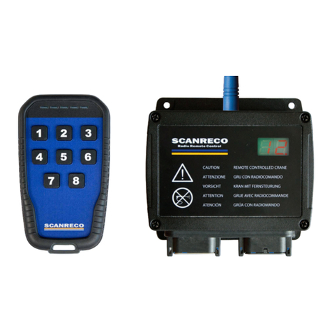
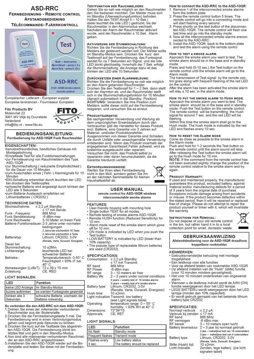
StarLogixs GateKeeper RR-07 User manual

Operating Instructions
GateKeeper
Remote System
Complies To:
AS/NZS4251.1.1999
FCCPart15(B)
N10728
R
For Rev2.0 Units
Receiver Model: RR-07
Remote Model : RT-07

Contents
1. Remote Set-up……..…………………….…....3
2. Receiver Set-up…………………………….…4
3. Control unction…….………………….……5
4. Range and Interference…………………..…..5
5. Receiver Connector Pin-Outs……………...6
6. Standard Receiver Wiring Connections….6
7. Switching Inductive Loads……………...…..7
8. Driving an Electric Motor-
Reversible Direction………………………….9
9. Trouble Shooting……………………………..10
10. Specifications………………………………….11

4 Or Less Controlled Devices
You only require one remote.
Leave it set on the factory default
Low Channel range.
5 to 8 Controlled Devices
You will require two remotes with
one set on Low Channel and the
other on High Channel.
A) Remove the battery lid and
remove both batteries.
B) Remove 2 screws from
enclosure back. Rotate
enclosure front up as shown.
Take care not to damage or
pull on the touch pad wire
tail.
C) Set jumper shunt to the two
pins on the channel select
jumper closest to the ‘High
Ch’ label on the circuit board.
D) Re-assemble the unit in
reverse order to disassembly
1.
1) Select a channel you wish to associate
with a controlled device. Note a
channel is a horizontal pair of keys,
one for open and the other for close.
2) The high channel number is on the
upper left corner of the key, and the
low channel number is on the lower
right corner of the key. (See above for
selecting high or low channel). This
channel number is required in the
receiver set-up.
Remote Set-up
Note: the SEND light should illuminate
when the Remote is transmitting.
Remember: after you have selected a pair
of keys for a function, place supplied
stickers on the keys to indicate their
function.
2
Changing to High Channel Mode
If two remotes are being used and they are more than 50 meters apart it should be
possible to operate them both in low channel mode. Only change one to high chan-
nel if they interfere with each other—that is intermittent or unpredictable response
when both remotes are operated.
Selecting a Channel

A) Remove 4 screws and remove case lid.
B) Using a small flat blade screwdriver rotate the channel switch until
the arrow points at the channel number selected in Step 2 of remote
set-up.
C) Refit the case lid. Take care to ensure lid seal is in place.
Note 1: Power must be off when adjusting the channel switch.
Note 2: When the case lid is removed four holes next to the case lid
screw holes can be accessed for mounting the unit. Only use
these holes—DO NOT drill any extra holes in the case.
2. Receiver Set-up
3
Setting the Receiver Channel

3. Control unction
All functions on the remote unit are a 'dead-man' type operation. That is - the
function only works while the key is held depressed. As soon as the key is
released the device being controlled will stop.
The Close key on the remote will drive N/O 1 on the receiver.
The Open key on the remote will drive N/O 2 on the receiver.
4.
.
Range and Interference
The system should work with the remote unit up to 15 meters from the
receiver. In many cases it may be possible to obtain adequate function at
greater distances. Obstacles like steel buildings and metal structures
between the remote and receiver may adversely impact on reliable
operation.
The system depends on a low power 433.92MHz radio link, and strong radio
transmitters in this frequency region may block communication. UHF two
way radios could be one such source of interference.
This system is NOT designed to be used in any safety critical
application. The safety rating of the system would be Category I as
specified by AS4024.1.
5

The GateKeeper System has been designed to be flexible and configur-
able thus enabling its use in many applications without modification. The
receiver has simple connection options that should allow for all common
actuator wiring configurations.
Note: the ‘actuator’ is whatever device the receiver has to drive to
cause the controlled device to move. For example pneumatic or
hydraulic solenoid coils, electric motors etc.
Wire entry is via a waterproof cable gland and it is recommended to use
a circular cable, so as to allow a good environmental seal. Farnell 388-
4650 seven core 0.75mm
2
or similar flex would be suitable. Also it is ad-
vised to crimp a bootlace ferrule (Farnell 997-2080 or similar) to each
conductor before fitting to PCB connectors.
Receiver Connector Pin-outs 5.
The receiver connectors are located on the receiver printed circuit board.
The pin-out is shown below. The receiver must be powered by a stable
12V dc power source. The receiver has an internal self-resetting fuse, but
it is also advisable to fit an in-line 1 amp fast blow fuse in the +ve power
wire.
6
Connector Pin-Out

Switching Inductive Loads
No special precautions are necessary when switching inductive loads
(that is things like solenoid coils). Protection circuitry is built into the re-
ceiver, and will work with AC or DC loads.
7.
Connection is as below:
7
Standard Receiver Wiring Connections 6.
The above wiring scheme should work for most applications, however
the normally open relay contacts in the Receiver can be wired in vari-
ous other circuit layouts depending on specific electrical requirements.
The exact design of specialised applications is beyond the scope of
this document.
Note: it is not possible to switch voltages greater than 12v dc or
ac. The relay contacts in the receiver have a protection circuit
that will not work above 12v. If it is necessary to switch higher
voltages then the receiver contacts must be wired to control ex
ternal switching relays.

8. Driving an Electric Motor - Reversible Direction
If the motor is 12v then the motor power source and the receiver power
source could be the same unit. Separate power sources allow for differ-
ent motor voltages. To allow the motor to be reversed using this scheme
the motor must be a DC type. Also note that this system requires two sin-
gle pole double throw relays mounted externally to the receiver unit. The
relay contacts and motor power source should have sufficient rated cur-
rent capacity at full motor load. Also no protection fuses are shown, but
must be fitted as deemed appropriate to protect the motor, motor power
source, relay contacts and wiring.
Motors with large inertial loads will take some time to ‘run-down’ and in
the process can generate considerable energy. When the motor is de-
energised the relay contacts are as shown above and currents can circu-
late through the N/C contacts of the external relays during the ‘run-down’
time. The relay contacts and wiring must be rated for this condition, or
some form of energy control and dissipation circuit fitted. 9

9
.
Trouble Shooting
No Function
1) Ensure the remote unit has fresh batteries. Only use quality AA
alkaline type dry cell batteries.
2) Ensure the receiver unit is powered with a 12V dc supply, and that
the supply is capable of supplying the current requirements of any
actuators fitted. Check that the power LED is illuminated. Check polarity
of supply voltage to receiver.
3) Double check the channel has been set correctly on the receiver.
4) Check that the correct channel range (high or low) is selected with
the jumper in the remote unit.
5) Observe the receiver LED's while pressing the open or closed key of
the associated channel on the remote. If the LED's light then the
problem is most likely to be in the wiring between the receiver and the
actuators ( or in the actuator system it's-self ).
Poor Control Range
1) Ensure the remote unit has fresh batteries. Only use quality AA
alkaline type dry cell batteries.
2) Check that the path between the remote and the receiver is not
obstructed by large metallic obstacles.
3) Check that no other high powered radio transmitters are operating
nearby.
10

10. Specifications
Remote Unit
Transmission Frequency 433.92MHz
Transmission Bandwidth 100kHz
Transmission Power 3dBm
Power Supply 3 x AAA Batteries
Standby Current Draw 4uA
Transmit Current Draw 4mA
Low Band Channels 6
High Band Channels 6
Channel Encoding Digital PWM
Dimensions 117x78x24mm
Weight (including batteries) 140g
Environmental Sealing IP55
Receiver Unit
Receive Frequency 433.92MHz
Receive Sensitivity -104dBm
Channels 12
Channel Decoding Digital
Dimensions 100x100x55mm
Environmental Sealing IP65
11

Your Sales Agent:
Warranty
Your StarLogixs GateKeeper Remote System is guaranteed against faulty
workmanship or components for a period of twelve months after the purchase
date. For warranty contact your local sales agent with proof of purchase date.
This warranty does not cover damage or failure cause by or attributable to Acts of
God, abuse, misuse, improper maintenance, lightning or other incidence of
excessive voltage or any repairs other than those provided by an authorised
StarLogixs service facility, or transportation costs.
StarLogixs is not responsible or liable for indirect, special, or consequential
damages arising out of or in connection with the use or performance of the system
or other damages with respect to any economic loss, loss of property, loss of
revenues or profit, or cost of removal, installation or reinstallation.
There will be charges rendered for repairs to the product made after the expiration
of the aforesaid twelve month warranty period.
•This warranty gives you specific legal rights and you may have other rights
which vary from state to state.
Copyright
Copyright 2001 by Starlogixs Pty Ltd.
All rights reserved.
The contents of this document, GateKeeper Remote System, front panel artwork, printed
circuit board artwork, and firmware (programs contained in the GateKeeper Remote System
integrated circuits) are subject to copyright and can not be reproduced, transmitted into any
language or computer language, in any form or any means, electronic, mechanical, magnetic,
optical, chemical, manual, or otherwise, without prior written consent from Starlogixs Pty. Ltd.
Trademarks
The symbols
are subject to Australian and international Trademark registrations, and their use is expressly
prohibited without written consent from Starlogixs Pty Ltd.
GateKeeper and
This manual suits for next models
1
Table of contents

