Starrett MVR200 User manual

MVR200 & MVR300
Manual Video Metrology Systems
User Manual
Starrett Kinemetric Engineering
26052 Merit Circle, Suite 103
Laguna Hills, CA 92653, USA
www.starrettkinemetric.com
Phone: (949) 348-1213
Fax: (949) 582-8040

- 2 -
Table of Contents
1. PREFACE...............................................................................................................................................3
1.1 Welcome......................................................................................................................................3
1.2 Safety Symbols & Terminology....................................................................................................3
1.3 Warranty ......................................................................................................................................3
1.4 Regulatory Compliance ...............................................................................................................4
1.5 Disclaimer of Liabilities................................................................................................................4
1.6 Copyright & Trademark Information ............................................................................................4
2. PRODUCT DESCRIPTION ....................................................................................................................5
2.1 Overview......................................................................................................................................5
2.2 MVR Options ...............................................................................................................................5
3. System Specifications .........................................................................................................................6
3.1 MVR200 & MVR300 System Components..................................................................................7
3.2 Operator Controls and Electrical Connections ............................................................................7
3.3 Changing Optics Assemblies.......................................................................................................9
3.4
Optimizing Substage Illumination
............................................................................................10
3.5
Mechanically Leveling the Stage Glass
..................................................................................10
3.6 Environmental Considerations...................................................................................................11
3.7 Safety Considerations................................................................................................................12
3.8 Equipment On/Off Control .........................................................................................................12
3.9
Fuses
.........................................................................................................................................12
4. INSTALLATION ...................................................................................................................................13
4.1 Moving the Equipment...............................................................................................................13
4.2 Uncrating the Equipment...........................................................................................................13
4.3 Placing the Equipment...............................................................................................................13
4.4 Removing Shipping Retainers...................................................................................................15
4.5 Electrical Connections...............................................................................................................16
4.6 On-site Functional Test, Calibration and Training.....................................................................17
5. MEASUREMENT STRATEGY.............................................................................................................18
5.1 Telecentric Lens Measurement Strategy...................................................................................18
5.2 Zoom Optics Measurement Strategy.........................................................................................18
5.3 Illumination Strategy..................................................................................................................18
5.4 Magnification Strategy...............................................................................................................18
5.5 Focus Strategy...........................................................................................................................19
5.6 Parts Fixturing............................................................................................................................19
5.7 M3 Software Operation..............................................................................................................19
6. SYSTEM MAINTENANCE ...................................................................................................................20
6.1 Daily Inspections........................................................................................................................20
6.2 Weekly or Monthly Maintenance ...............................................................................................20
6.3 Zoom Optics Alignment Verification ..........................................................................................20
6.3.1
Zoom Optics Parfocality & Focus
...................................................................................20
6.3.2
Zoom Optics Parcentricity
...............................................................................................21
6.3.3
Zoom Optics Squareness
................................................................................................21
6.4 Calibration Verification...............................................................................................................22
6.5 Cleaning.....................................................................................................................................23
6.5.1
Cleaning External Surfaces
.............................................................................................23
6.5.2
Cleaning Optics
................................................................................................................23
7. GLOSSARY .........................................................................................................................................25

- 3 -
1. PREFACE
1.1 Welcome
Thank you for purchasing an MVR200 or MVR300 Manual Video Metrology System. We are
pleased that your search has led you to Starrett Kinemetric
Engineering, a subsidiary of the L.S.
Starrett Company.
This manual is intended to maximize your satisfaction with your system and
ensure the most in operating performance. Feel free to contact Starrett Kinemetric Engineering
at any time. We value your feedback and your satisfaction as a customer.
1.2 Safety Symbols & Terminology
The following symbols and terms are used in this manual to call attention to important safety
issues. Heed these notices carefully in order to avoid personal injury or damage to the system.
Symbol
or Term
Meaning
CAUTION:
Failure to heed the message may result in personal injury or
equipment damage.
WARNING:
Dangerous voltage. Risk of electrical shock. Failure to observe this
warning may result in equipment damage, personal injury or death.
WARNING:
Disconnect equipment from power source. Failure to observe this
warning may result in equipment damage, personal injury or death.
CAUTION:
Pinch Point - Keep hands clear. Failure to observe this warning may
result in minor to severe personal injury or equipment damage.
DANGER
Immediate hazard which could result in severe personal injury or death.
WARNING
Hazard or unsafe practice which could result in personal injury.
CAUTION
Hazard or unsafe practice which could result in equipment damage or minor injury.
NOTE
Information that is helpful in properly operating the equipment.
CAUTION
Hazard or unsafe practice which could result in equipment damage or minor injury.
NOTE
Information that is helpful in properly operating the equipment.
1.3 Warranty
Starrett Kinemetric Engineering (SKE) products carry a one-year warranty from date of purchase
against defects in material or workmanship (parts and labor), subject to factory inspection
.
The
L.S. Starrett Company will repair or replace, at its option, any part or parts found to be defective
in material or workmanship. Starrett warrants repaired or replaced parts for the balance of the
original warranty period or 90 days, whichever is longer. Parts returned to the factory under war-
ranty will be repaired at no charge. Freight charges to the factory will be paid by the customer.
Return freight charges to the customer will be paid by Starrett.
This warranty does not cover damages from such causes as abuse, accident, neglect, fire or
freight damage. It does not apply to defects resulting from modifications made by the customer
or improper use of the system or its components.

- 4 -
1.4 Regulatory Compliance
The MVR200 and MVR300 Video Metrology Systems have been inspected, tested, and
evaluated by independent test laboratories and are declared to comply with Council Directives
2006/42/EC - Machinery and 2002/95/EC RoHS (by exemption) when installed and operated in
accordance with this manual. Accordingly, these systems are entitled to bear the CE Mark. The
Product Safety, EMC Testing and Evaluation reports can be provided upon request.
EMC Test Standards
EN 61326-1:2013
CISPR 11:2003+A1:2004 +A2:2006
Radiated and Conducted Emissions
IEC 61000-4-2:2009
Electrostatic Discharge Immunity
IEC 61000-4-5:2006
Power Line Surge Immunity
IEC 61000-4-4:2012
Electrical Fast Transients Burst Immunity
EN 61000-4-6:2009
RF Common Mode Immunity
IEC 61000-4-3:2006 +A2:2010
Radio Frequency Immunity
IEC 61000-4-8:2010
Power Frequency Magnetic Field Immunity
IEC 61000-4-11:2004
Voltage Dips and Short Interruptions Immunity
Safety Standards
EN 60204-1:2006+A1:2009
Safety of Machinery, Electrical Equipment of Machines
EN 12100
Safety of Machinery, Principles for Risk Assessment
1.5 Disclaimer of Liabilities
The L.S. Starrett Company shall have no liability or responsibility to the customer or any other
person or entity with respect to any liability, loss or damage caused or alleged to be caused
directly or indirectly by this documentation, or the hardware and software described in it. This
includes, but is not limited to, any interruption of service, loss of business or anticipatory profits,
or consequential damages resulting from the use or operation of hardware or equipment.
1.6 Copyright & Trademark Information
MVR200™and MVR300™are trademarks of the L.S. Starrett Company.
M3™is a trademark of
MetLogix, Inc.
Windows
®
is a registered trademark of Microsoft Corporation
.

- 5 -
2. PRODUCT DESCRIPTION
2.1 Overview
The MVR Series of advanced benchtop manual video metrology system consists of two base
models: the MVR200 with 200 x 100 x 200 mm (8” x 4” x 8”) of X-Y-Z travel, and the MVR300 with
300 x 200 x 200 mm (12” x 8” x 8”) of X-Y-Z travel.
Both MVR models feature a granite base for stability, recirculating ball linear guides for smooth
stage motion, and a motorized Z-axis. All electronics other than in the system’s PC are housed in
the Z-column, providing a clean, integrated system with minimal external wiring. Two high-speed
data cables carry all signals between the metrology unit and PC. Superb metrology performance
is provided by 0.5 micron resolution linear encoders, a high-resolution color video camera, two-
channel LED lighting, and precision optics, which can be 6.5:1 manual zoom optics or any of six
telecentric lenses for field-of-view (FOV) measurements. FOV measurements can encompass an
entire small part up to 2.00” x 1.50” or a feature of a larger part and be seamlessly integrated with
stage motion to measure parts with a length up to 200 mm (MVR200) or 300 mm (MVR300).
The operator interface is a 21.5” all-in-one touch screen PC which runs MetLogix M3 FOV soft-
ware under Windows® 7 Professional. This software supports 3-axis measurements and 2D
geometrical constructs (points, lines, angles, rectangles). The screen displays a live video image
of the part plus geometry tools and digital readings. The image of the part can be resized using
zoom, and measurements can be taken by simply tapping a feature on the screen. A keyboard
and a wireless mouse are also provided, and are used for file operations.
With the M3 DXF/FOV option pack, DXF CAD files can be imported over a network and be auto-
matically compared to actual measurements.
2.2 MVR Options
The MVR Series is available as basic MVR200 or MVR300 systems with factory installed manual
zoom optics, and as MVR200 or MVR300 FOV systems with a bayonet lens mount for quick
change of optics by the user.
The basic MVR200 and MVR300 systems come with a 1 Mpixel color video camera and 6.5:1
manually adjustable zoom optics. Two-channel illumination is provided by an LED ring light and
collimated LED sub-stage lighting.
The MVR200 FOV and MVR300 FOV systems come with a 2 Mpixel color video camera and
a bayonet lens mount which accepts a 6.5:1 manual zoom lens or any of six available fixed
magnification telecentric lenses (0.30X, 0.50X, 0.80X, 1.0X, 2.0X, 4.0X), where the stated
magnification is the image size on the camera CCD divided by the corresponding object size.
Options include auxiliary lenses for the zoom optics (0.5X, 1.5X, 2.0X), a choice of NIST-traceable
calibration standards, and an ergonomic workstation.

- 6 -
3. System Specifications
Feature
MVR200
MVR300
Measurement Range, X-Y-Z
200
x
100
x
200
mm (8”
x
4”
x
8”)
300
x
200
x 200
mm (12”
x
8”
x
8”)
Unit Dimensions, H x W x D
865 x 600 x 645 mm
(34” x 23.7” x 25.4”)
865 x 790 x 865 mm
(34” x 31” x 34”)
Metrology Base
Granite
Reading Resolution, X-Y-Z
0.5 µm (0.00002”)
Reading Accuracy, X-Y-Z
Accuracy: 1.9 µm + 5L/1000 for X and Y, 2.5 µm + 5L/1000 for Z
Motion Control
Manual X and Y, motorized Z
Substage Illumination
LED illumination matched to camera optics
Surface Illumination
LED ring light
Camera Resolution
1 MP (
1024 x 768 pixels) for basic models with dedicated zoom optics
2 MP (1620 x 1236 pixels) for models with bayonet lens mount
Image Update Rate
15 frames/sec, including image processing
Computer Hardware
All-in-one PC with 55 cm (21.5”) color touch screen, 4 GB RAM
Computer Interfaces
Ethernet (1 GB/sec), Wi-Fi, four USB 2.0 ports
Data Storage
500 GB hard disk
Operating System
Windows
®
7 Professional
Application Software
MetLogic M3 metrology software and DXF/FOV option pack
Geometrical Constructs
2D geometries plus height
Comparison to CAD Files
DXF CAD file import, automatic comparison to CAD files
Operator Controls
Computer touch-screen, keyboard with integral touchpad
Optics Mounting
Fixed mount or bayonet fitting for quick optics changes
Power for Metrology Unit
“Brick” type AC adapter, 100/240 Vac input, 24V, 5A output
Power for All-in-One PC
“Brick” type AC adapter, 100/240 Vac input, 19.5V, 7.9A output
Zoom Optics
6.5:1 Zoom
Magnification on CCD
0.70X to 4.50X
Field of View Width
10 to 1.6 mm (0.39” to 0.06”)
Magnification on Monitor
31X to 200X
Zoom Working Distance
88 mm
Available Auxiliary Lenses
0.5X, 1.5X, 2.0X
Telecentric Optics
0.30
0.50
0.80
1.0
2.0
4.0
Magnification on CCD
0.30X
0.50X
0.80X
1.0X
2.0X
4.0X
Magnification on Monitor
13X
22X
36X
45X
89X
178X
Field of View Width
24 mm
0.93”
14 mm
0.56”
8.9 mm
0.35”
7.1 mm
0.28”
3.6 mm.
0.14”
1.8 mm
0.07”
Optical Distortion (ΔH/H)
0.003%
0.018%
0.009%
0.003%
0.006%
0.005%
Telecentric Working Dist.
110 mm
*
At 1:1 pixel setting
Disclaimer: Due to continual product improvements, specifications may change without notice.
- 7 -
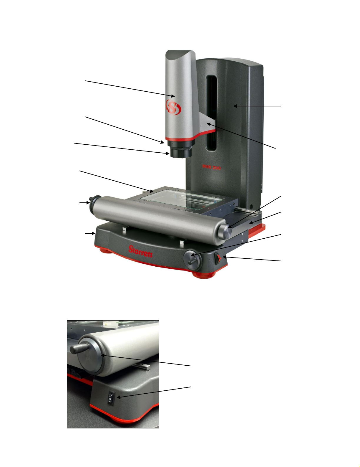
3.1 MVR200 & MVR300 System Components
MVR200 benchtop vision metrology system
3.2 Operator Controls and Electrical Connections
Operator Controls on Left Side
HandwheelwithcrankforX-axismotion
Three-position toggle switchfor fine/coarse speed
controlof Z-axistravel.
Video probe with
video camera
and telecentric
or zoom optics
Bayonet mount
for quick-change
optics (if ordered)
LED surface
illumination
X-Y stage with
LED substage
illumination
Hand wheel for
manual X-axis
travel
Three-position
toggle switch for
fine/coarse speed
control of Z-axis
travel
Machined Z column
with plastic cover.
Houses all electronics
other than touch-screen
PC.
200 mm (8”) of
motorized vertical
Z-axis travel
Knob for X-axis travel
Granite base
Hand wheel for Y-axis
travel
Proportional speed
control switch for up-
down Z-axis travel

- 8 -
Operator Controls on Right Side
Knob for X-axismotion. Attachedtosameshaft as
handwheel onleftsideofmachine.
HandwheelwithcrankforY-axis motion
Proportional speed control switch for up-down
Z-axis travel
On-OffSwitch and Electrical Connections
On-Off switch.Usedtoturnmachineoffwhen notinuse.
24 Vdc power input from ‘brick” type power supply on
floor.
USBconnectiontoall-in-onePCforencodersignals.
USBor Ethernetconnectiontoall-in-onePC forcamera
signal. Thechoice ofUSB orEthernetdependsonthe
type of camera.
Electronics Compartmentin Back
The backofthemetrologyunit is hingedandholdsacompartmentwithallelectronicsotherthantheall-in-one
PC.Removingtwoknurledhand-screwsprovides accesstothiscompartment.Thisisforserviceaccess only.
There areno useradjustmentsor controlsbehindthehingedback.
- 9 -
3.3 Changing Optics Assemblies
MVR systems equipped with a bayonet optics mount allow their optics assemblies to be changed
quickly by the user, for example to switch from zoom operation to fixed-magnification telecentric
measurements, or to switch between telecentric lenses with different magnifications.
NOTE
T
he positioning of different optics assemblies in the bayonet mount is not
exact, so do not change optics in the middle of a measurement run.
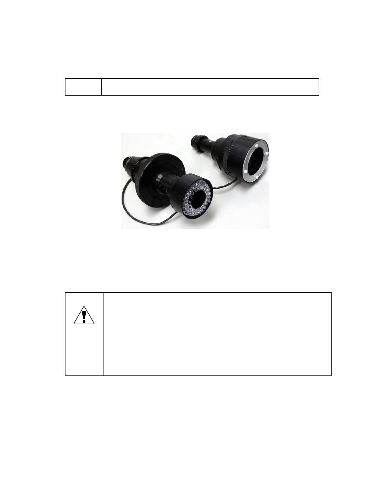
An LED quad ring light is normally part of the 6.5:1 zoom optics assembly and should always
remain attached to that assembly. A different LED ring lights fits all telecentric lens assemblies
from 0.3X to 4.0X. This ring light can be transferred from one telecentric lens to another when
these have been removed from the system.
6.5:1 zoom optics assembly (left), telecentric optics assembly (right)
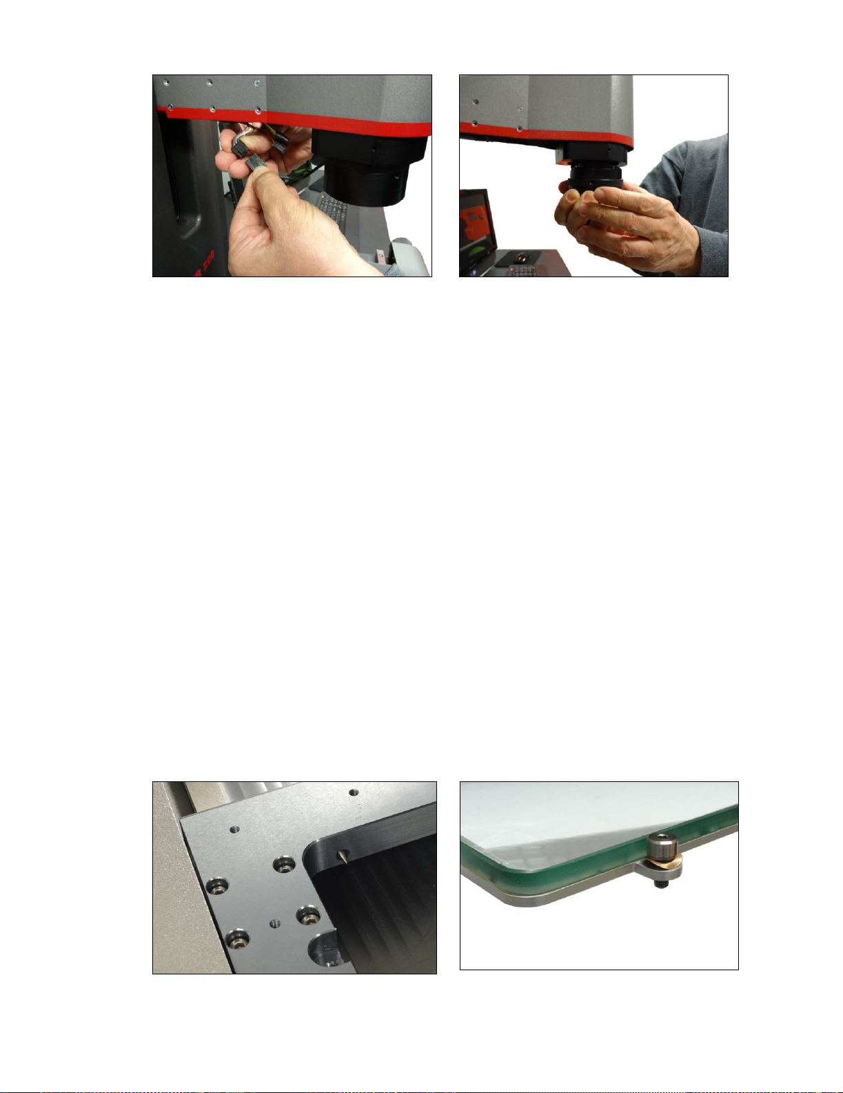
To remove a lens assembly from the system, first detach the electrical connections of the ring
light. Note that the electrical connectors are latched. Pry the plastic latch open with a flat-blade
screwdriver, and the two connector halves will separate easily. Give the optical assembly a quarter
turn counterclockwise, and the assembly will suddenly be released. Reverse the process to
reinstall.
Cautions
Use two hands to remove a lens assembly, as it is heavy and is suddenly released
after giving it a quarter turn counterclockwise. A drop onto the stage glass could
break the lens and the stage, causing expensive damage.
Do not leave the camera unprotected by a lens assembly to minimize dust settling on
the CCD sensor surface.
Do not touch optical surfaces, since oil from your hands can permanently
damage optical coatings.
Place unused lens assemblies in a polyethylene Ziploc bag for dirt protection.
Store unused lens assemblies in a safe place, since they are breakable and
expensive.
- 10 -
First unplug the ring light connector.
Then remove optics assembly using two hands.
3.4
Optimizing Substage Illumination
MVR systems with dedicated optics (zoom or telecentric) and without a quick-change bayonet
lens mount are shipped with LED substage illumination that is optimized for these optics. No
action is required by the user.
MVR systems with the quick-change bayonet lens mount require that substage illumination be
modified when switching between telecentric and zoom optics, since a smaller aperture will
produce better results with zoom optics. This is achieved by reducing the aperture of a variable
aperture if such an aperture is part of the system, or by dropping in an aperture plate if furnished
with the zoom optics.
Access to the substage lighting requires that the glass plate be removed from the MVR stage.
To do so, remove the four screws that secure the glass plate to the stage. Once these have been
removed, place two fingers in the spaces vacated by the screws and pry up one side of the glass
pate. Better yet, use a suction cup to pull up one side of the glass plate.
3.5
Mechanically Leveling the Stage Glass
The glass plate can be considered level if the video image of an artifact remains in focus at high
optical magnification for any stage position. MVR systems allow the glass plate to be leveled
mechanically by about 1.5 mm using four screws whose head has been machined to a conical tip.
Turn a screw clockwise with a 2.5 mm Allen wrench to move it toward the glass plate and raise
the stage. Turn a screw counterclockwise to move it away from the glass plate to lower it. Note
that glass does not rest directly on the conical tips, but is held by a steel frame. The glass plate
is secured by screws with a spring washer. Orient the washers as shown in the photo below,
keeping them barely compressed so that they have an adjustment range. Four-point support will
provide pivot action around two diagonal axes, so make screw adjustments until the image
remains in focus and the glass plate no longer tips around a diagonal axis.
Conical tip, indentation for attachment
screw with spring washer
Glass plate with steel base and attachment
screw with spring washer

- 11 -
3.6 Environmental Considerations
MVR systems are factory calibrated under the standard laboratory environmental conditions
shown below:
Specification
Requirement
Ambient Temperature
20°C ± 0.5°C (68°F ± 1°F)
Humidity
40-60% RH
Temperature rate of change
0.5°C (1°F) per hour
If the system is to be operated under environmental conditions that are substantially different
from those shown above, the system should be recalibrated under the expected conditions
.
Users should also consider the
material characteristics of the parts under inspection, in particular
coefficients of thermal expansion. Numerical compensation may be required when measuring
parts under conditions different from those controlling the stated dimensional specifications for
these parts.
- 12 -
3.7 Safety Considerations
General
Safety
MVR vision metrology systems are designed for safety and proper ergonomics during
normal use. Exercise caution when lifting, handling or moving the system to avoid
personal injury and to maintain equipment calibration and measurement performance.
Disconnect all power sources prior to moving or working on the equipment. Consult
Starrett if you have any question regarding transporting, using or maintaining this
system.
Electrical
Safety
MVR vision metrology systems do not contain hazardous AC line voltages, as these
are contained on the input side of the system’s two AC adapters, which are UL listed.
The supplied voltages are 24 Vdc to the metrology unit and 19.5 Vdc to the all-in-one
PC. Even at these low voltages, there is the potential of electrical equipment damage
caused by accidental short circuits. For maximum electrical safety and minimal risk to
the equipment, follow the guidelines below:
Ensure that the power receptacles for the AC adapters are properly grounded 3-
prong polarized 120V AC types for use in North America or appropriate safety-rated
receptacles for use outside of North America.
Do not operate the system with the housing open except for service by a factory trained
technician.
Keep liquids away from the system, and do not operate the equipment in excessively
humid conditions, as water can cause short circuits.
Keep metal filings away from the system, as such debris can cause short circuits.
Do not operate the equipment around volatile or flammable solvents, as local electrical
heating could cause ignition.
Disconnect power, or do not plug in the power cord, if hazardous conditions exist such
as a damaged or frayed power cord, a damaged or improperly grounded power recep-
tacle, equipment exposure to liquid spills or excessive moisture, or impact damage.
Have the system inspected by authorized personnel before operating.
Mechanical
Safety
MVR systems are heavy. To avoid possible back injury, use multiple persons to lift.
Bend your knees, not your back.
There are moving components and potential pinch points, so do not place hands and
mechanical items near pinch points. The risk of injury from these pinch points is
minimal, since all motion is slow and manual, not motorized.
3.8 Equipment On/Off Control
MVR systems have two On/Off switches: one on the back right of the metrology unit right above
the electrical connections, and one in the upper left of the all-in-one PC. Turn the system off when
not in use.
Before removing power, first close all computer files and applications, then shut
down the computer using the Windows “Shut down” button. Otherwise computer
files could be corrupted by the sudden loss of power.
3.9
Fuses
There are no fuses in the system.
- 13 -
4. INSTALLATION
Starrett Kinemetric vision metrology systems and optical comparator systems are normally
installed by a factory-trained installer who also provides operator training. The information below
covers basic hardware installation in the event that such an installer is not available.
4.1 Moving the Equipment
MVR metrology units are shipped in a wooden shipping crate. Use a forklift or pallet cart to move
the crate within the building to the final location where the system will be installed. Exercise care in
handling the unopened shipping crate, as excessive force or a drop may damage its contents.
4.2 Uncrating the Equipment
The following items are required to uncrate and install an MVR system:
1.
Battery powered drill with Phillips bit (to remove top and sides of shipping crate).
2.
Crescent wrench (to remove screws which attach shipping tabs to the crate).
3.
Bubble level (optional, to level workbench or workstation).
4.
Other common hand tools.
4.3 Placing the Equipment
A clean operating environment is recommended to minimize the accumulation of dirt on the optics
and on precision mechanical parts, such as lead screws and encoder scales.
MVR systems are designed to be installed on a benchtop at a height of approximately 85 cm
(33.5”), which is the height of Starrett’s ergonomic workstation. A level work surface, as checked
with a bubble level, is recommended, but is not essential. Allow 60 cm (24”) to right or left side
of the metrology unit to position the all-in-one PC. An additional clearance of 30 cm (12”) on both
sides is recommended for general access. Allow a minimum of 5 cm (2”) behind the unit for air
floor, as the electronics compartment only uses convective air cooling. Please refer to the
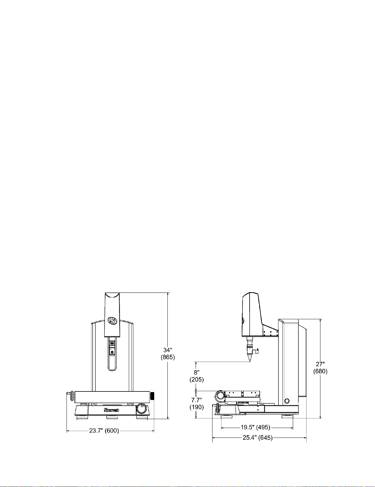
drawings below for dimensions of the MVR200 and MVR300 metrology units.
Completely opening the hinged door at the back of the metrology unit for service access requires
an additional 50 cm (20”) of space. The metrology unit can be moved as needed for service.
MVR200 metrology unit dimensions
- 14 -
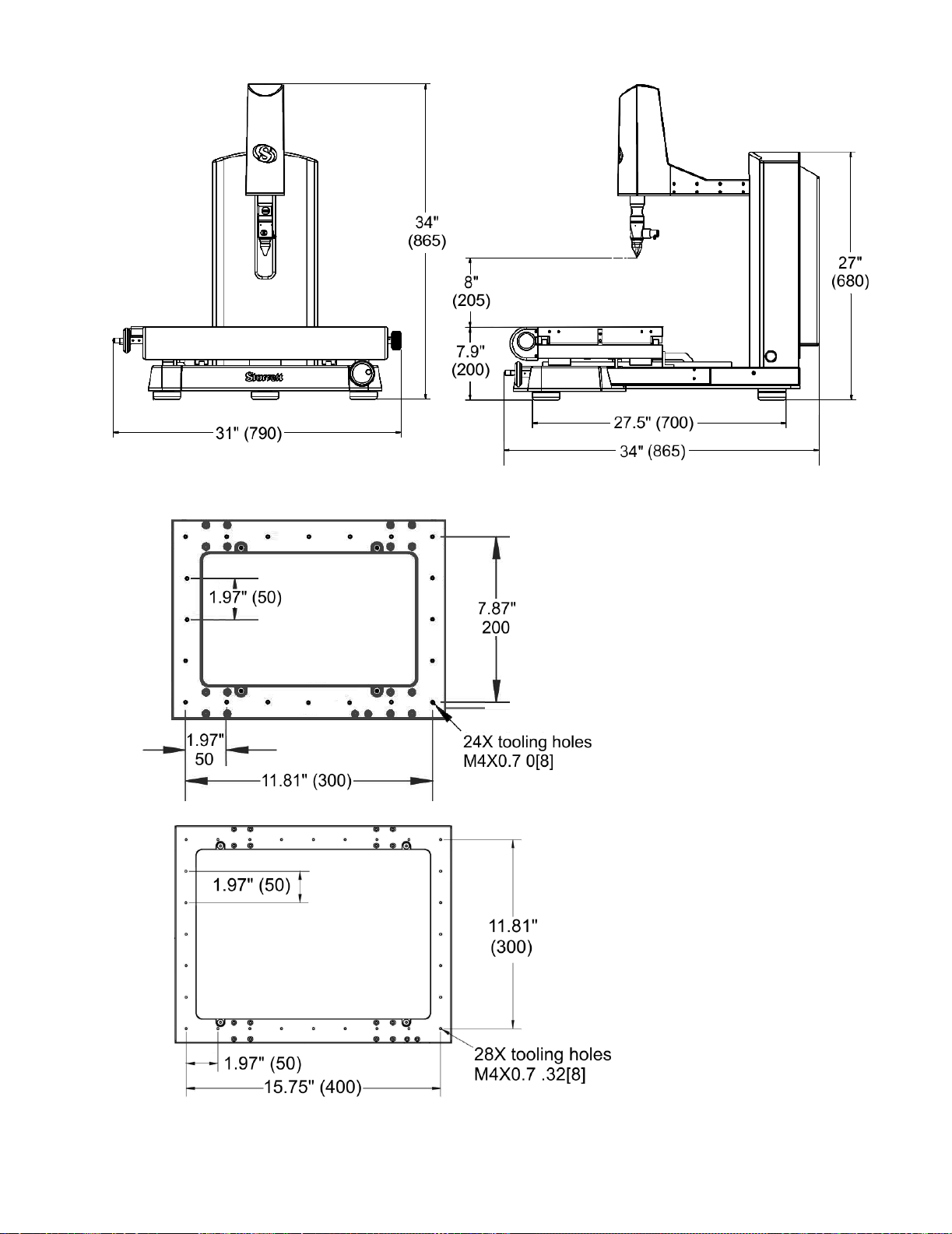
MVR300 metrology unit dimensions
MVR200 tooling holes
MVR300 tooling holes

- 15 -
4.4 Removing Shipping Retainers
MVR systems (and other Starrett metrology systems) use metal tabs to prevent movement of
critical components during shipment. Anodized red for easy identification, these are intended to
be removed once the equipment has been placed in its final position. Look for any red tabs and
remove them. There is also a red tab inside the electronics housing, so open the hinged door at
the back of the metrology unit and remove that tab also.
MVR300 metrology units are shipped with two red carrying handles near the back of the base.
These can be removed or be left on the system following installation to facilitate possible later
lifting.
MVR300 metrology units are also shipped with a lift bar toward the front of the base. This bar is
used to secure the units in their shipping crate and can also be used for lifting. This bar slides
out and is normally removed once the system is installed.
Also remove any tape and packing materials that may have been added for shipment.
Please refer to the drawings below for the locations of MVR300 red retainer tabs, carrying
handles, and the lift bar.
Location of MVR300 red retainer tabs, lifting handles, and slider bar
Shipping
tabs
Carrying
handles
Removable
lift bar

- 16 -
4.5 Electrical Connections
MVR systems are powered by two “brick” type AC
adapters, one for the metrology unit (19.5 Vdc out-
put) and one for the all-in-one PC (24 Vdc output).
Both accept 100/240 Vac power for worldwide use.
The maximum combined current draw is 3.6A at
120 Vac or 1.8A at 240 Vac. Verify that the power
outlet is rated for at least these currents.
The adapters are normally placed on the floor.
Before doing so, verify that the floor will never
be flooded or hosed down for cleaning. If there is
danger of contact with water on the floor, place the
adapters in a higher, protected location.

- 17 -
4.6 On-site Functional Test, Calibration and Training
All Starrett vision metrology systems and optical comparators are calibrated at the factory prior
to shipment; however, it is possible that components may have moved during shipment. A
complete functional test and calibration are recommended following physical installation.
Professional system installation is normally provided by Starrett for all new vision metrology
systems and optical comparators sold in North America. Installation includes equipment setup,
on-site calibration and on-site operator training. While professional installation is a separately-
quoted line item, it is highly recommended and is purchased by most users.
As part of its setup services, Starrett oversees the equipment’s in-plant transportation to its
permanent location and uncrating. Starrett then performs the physical setup and electrical
connection, followed by a completed functional checkout. This typically takes 1/2 day for a
manual system. The system is then allowed to temperature stabilize overnight.
On-site calibration normally takes place on the day following setup. Calibration uses NIST-
traceable glass grids and gage blocks. Calibration typically takes 1/2 day for an MVR manual
system.
On-site basic operator training is provided following calibration. This typically takes 1/2 day
for an MVR manual system. Many customers choose to augment basic training with additional
hands-on training, where new operators program actual parts of the type on which they will be
working. Training is with the new equipment and is limited to 1 to 3 people, so that these can all
get hands-on time. Starrett’s objective is to create power users, who can then train other users
when needed.
Installation services in North America (USA, Canada and Mexico) are provided by professional
installers and service technicians operating out of the Laguna Hills, CA, headquarters of
Starrett Kinemetric and its regional sales offices. Outside of North America, installation services
are provided by Starrett subsidiaries in Brazil (for South America), Scotland (for Europe and
Africa), China (for Mainland China), and Singapore (for Southeast Asia and Australia).

- 18 -
5. MEASUREMENT STRATEGY
MVR systems can be operated with any of 6 telecentric fixed-focus lenses with magnification from
0.30X to 4.0X or with 6.5:1 zoom optics with continuously adjustable magnification from 0.7X to
4.5X. Magnification is the image size at the camera CCD detector place divided by the object size.
Since the CCD size is fixed (namely 9.93 x 8.70 mm for the 2 Mpixel camera), each magnification
has a corresponding field of view (FOV), which is the CCD size divided by magnification. The
higher the magnification, the higher the resolution but the smaller the field of view.
Note that the centering of the optics can vary by a small amount in the quick-change bayonet
optics mount, so all measurements on the same part need to be taken with the same optics.
5.1 Telecentric Lens Measurement Strategy
Select telecentric optics to perform high accuracy, high throughput field-of-view (FOV) measure-
ments. If all measurements are to be in the FOV, select the highest magnification lens whose
FOV encompasses the entire part. The 0.30X lens accommodates parts up to 51 x 38 mm (2.00”
x 1.50”). If the entire part cannot fit into the FOV, no problem. Simply move the stage by up to 200
mm (8”) for the MVR200 or 300 mm (12") for the MVR300, and the M3 software will seamlessly
integrate FOV measurements with encoder readings from stage motion.
5.2 Zoom Optics Measurement Strategy
The 6.5:1 zoom optics allows magnification to be continuously adjusted from 0.7X to 4.5X. While
the zoom optics can provide the same FOV as the four higher magnification telecentric lenses,
they do not offer the same low optical distortion that is required for accurate FOV measurements
across the entire FOV. However, they are equally as accurate as telecentric lenses when used at
high magnification in combination with stage motion.
Select zoom optics to measure large parts which would not fit into a single FOV, also for smaller
parts where extremely high magnification is required. The lowest zoom magnification setting
accommodates parts up to 11.2 x 9.4 mm (0.44" x 0.37") in the FOV. To measure large parts,
locate the edge of interest at minimum magnification, then take the actual measurement at maxi-
mum magnification using the system's crosshairs. The zoom optics’ parcentricity feature will
ensure that a feature will remain at the optical center of the video image throughout the
magnification range.
5.3 Illumination Strategy
Once the image has been properly focused and magnification has been set, adjust light levels
as necessary using the slider controls in M3 software. The right lighting is paramount to accurate
measurement with any video-based measurement system. Lighting that is too low will result in a
dark, low-contrast image with indiscernible features. Lighting that is too bright may result in a
washed-out image and blooming, or oversaturated bright regions that distort features
.
When adjusting lighting, start with light that is lower than desired, then increase lighting while
viewing the image on the monitor. Maintain constant lighting for consistent results. Always
use the same light level while sampling points for a single feature –do not to change light levels
during a measurement run.
Depending on the part characteristics and the feature being measured, the right combination
of lighting may aid in bringing out a particular feature. Take time to experiment by balancing the
available light sources.
5.4 Magnification Strategy
In general, higher magnification provides greater resolution and accuracy; however, not all
features should be inspected at the highest available magnification. Too high a magnification
may make it difficult to discern edges by exaggerating edge defects such as burrs or chips.
Try decreasing the magnification until the edge is more clearly identifiable.

- 19 -
Also consider factors such as tolerance requirements, manufacturing processes, functional requi-
rements and optical characteristics of the part. Features with loose tolerances may not need to be
inspected at high magnification. Select the magnification best suited for the requirements.
5.5 Focus Strategy
Accurate measurement requires proper focus of the image
. When measuring flat parts, always
first ensure that the stage glass has been leveled. When using zoom optics,
first focus the image
at highest magnification, then decrease the magnification to the desired level.
5.6 Parts Fixturing
The part must be fixtured securely to prevent part movement during measurement
.
Also, proper
alignment of the part to the stage can aid in measurement. If the part is off-axis from the stage,
X-Y-Z measurements will not correlate as well with the part dimensions. Aligning the part with the
X, Y and Z axes of the system will improve dimensional measurements. Orientation errors, or
skew errors, can also be removed by creating a reference frame based on the part before taking
measurements. Please see the M3 software manual for details.
5.7 M3 Software Operation
M3 software operation is outside of the scope this hardware-oriented user manual. Please refer to
the separate MetLogix M3 software manual.
- 20 -
6. SYSTEM MAINTENANCE
MVR vision metrology systems have been designed for years of superior service. Periodic
maintenance as outlined in this section should be performed to maintain the system in peak
operating condition.
Perform a daily inspection to ensure that the system is operating correctly and that proper
safety guidelines are being followed.
Periodically verify basic optical performance.
Periodically perform cleaning and lubrication.
Schedule regular factory-authorized calibration and maintenance service to preserve proper
function and accuracy
.
6.1 Daily Inspections
On a daily basis, inspect your system for general safety and basic functionality:
Verify that the work area is clean, dry and free of debris. Remove any debris or loose items
from around the system and metrology stage.
Verify that the electrical power cord is plugged into a grounded power source and is
unobstructed.
Verify that temperature and humidity are within recommended ranges.
Allow the system to warm up to normal operating temperature before performing critical parts
measurements.
6.2 Weekly or Monthly Maintenance
On a weekly or monthly basis (based on experience), do the following:
Inspect the system for cleanliness. If dirty, follow cleaning instructions stated under "Cleaning."
Verify that the stage control mechanisms move freely
. If it binds, call for service. The lead
screws use a self-lubricating TFE coating, which is designed to last for the life of the product.
Do not apply any grease or other lubricant.
Check the system for calibration against a certified chrome-on-glass standard.
6.3 Zoom Optics Alignment Verification
The system’s zoom optics (if ordered) should be verified regularly to ensure accurate measure-
ment. Parfocality, parcentricity and squareness verifications are straightforward and may be
performed as often as desired. Focus is adjusted as needed by changing the distance between
the lens and the surface being viewed.
CAUTION:
While optical alignment verification may be performed by an operator,
optical alignment correction should only be performed by an authorized service
technician
.
If alignment discrepancies are found, contact Starrett or your local
Starrett representative to schedule authorized service.
6.3.1 Zoom Optics Parfocality & Focus
Parfocality
is the condition in which the video image will remain in focus as the magnification
is adjusted from highest to lowest. Starrett zoom optics are designed to maintain parfocality
throughout their magnification range.
To check parfocality, always reference a flat, sharp edge. Do not select a rough or sloping feature.
The MAG checker provided with the system is an ideal part to check parfocality.
This manual suits for next models
1
Table of contents


