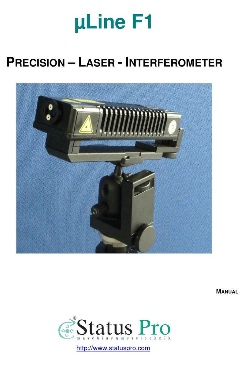
Status Pro mLine F1 User manual

Precision Laser Interferometer
User Manual
Another fine solution by
BA 1075 E

2Status Pro – µLine F1 User Manual
User Manual – English
(BG 840300)
Congratulations and thank you for choosing the Status Pro µLine F1 Laser Interferometer.
Before using it for the first time, please read notes on safety and instructions for use care-
fully. We wish you much joy and success in applying your newly acquired device for precise
displacement detection on machine tools or any other means of measurement you see fit.
Please be aware that here at Status Pro we are constantly improving our products. To
make sure you are reading the up-to-date manual, please go to www.statuspro.de and
download the most recent version.
1 NOTES ON SAFETY . . . . . . . . . . . . . . . . . . . . . . . . . . . . . . . . . . . . . . . . . . . . . . . . . . . . . . . . . . . . . 5
1.1 Laser Protection Class . . . . . . . . . . . . . . . . . . . . . . . . . . . . . . . . . . . . . . . . . . . . . . . . . . . . . . 5
1.2 Standards. . . . . . . . . . . . . . . . . . . . . . . . . . . . . . . . . . . . . . . . . . . . . . . . . . . . . . . . . . . . . . . . . . 6
1.3 Information on Batteries / Accumulators . . . . . . . . . . . . . . . . . . . . . . . . . . . . . . . . . . . . . . 6
1.4 Cleaning . . . . . . . . . . . . . . . . . . . . . . . . . . . . . . . . . . . . . . . . . . . . . . . . . . . . . . . . . . . . . . . . . . . 7
1.5 Service & Maintenance . . . . . . . . . . . . . . . . . . . . . . . . . . . . . . . . . . . . . . . . . . . . . . . . . . . . . 7
1.6 Calibration . . . . . . . . . . . . . . . . . . . . . . . . . . . . . . . . . . . . . . . . . . . . . . . . . . . . . . . . . . . . . . . . . 8
1.7 Disclaimer . . . . . . . . . . . . . . . . . . . . . . . . . . . . . . . . . . . . . . . . . . . . . . . . . . . . . . . . . . . . . . . . . 8
2 INTRODUCTION . . . . . . . . . . . . . . . . . . . . . . . . . . . . . . . . . . . . . . . . . . . . . . . . . . . . . . . . . . . . . . . . 9
3 INSTALLATION. . . . . . . . . . . . . . . . . . . . . . . . . . . . . . . . . . . . . . . . . . . . . . . . . . . . . . . . . . . . . . . . 10
3.1 System requirements. . . . . . . . . . . . . . . . . . . . . . . . . . . . . . . . . . . . . . . . . . . . . . . . . . . . . . . 10
3.2 Installing Software . . . . . . . . . . . . . . . . . . . . . . . . . . . . . . . . . . . . . . . . . . . . . . . . . . . . . . . . . 10
4 COMPONENTS. . . . . . . . . . . . . . . . . . . . . . . . . . . . . . . . . . . . . . . . . . . . . . . . . . . . . . . . . . . . . . . . 11
4.1 Required Components . . . . . . . . . . . . . . . . . . . . . . . . . . . . . . . . . . . . . . . . . . . . . . . . . . . . . . 11
4.2 Additional Components . . . . . . . . . . . . . . . . . . . . . . . . . . . . . . . . . . . . . . . . . . . . . . . . . . . . . 12
5 SETUP . . . . . . . . . . . . . . . . . . . . . . . . . . . . . . . . . . . . . . . . . . . . . . . . . . . . . . . . . . . . . . . . . . . . . . . 14
5.1 Software. . . . . . . . . . . . . . . . . . . . . . . . . . . . . . . . . . . . . . . . . . . . . . . . . . . . . . . . . . . . . . . . . . 14
5.2 Hardware . . . . . . . . . . . . . . . . . . . . . . . . . . . . . . . . . . . . . . . . . . . . . . . . . . . . . . . . . . . . . . . . . 14
Contents

Status Pro – µLine F1 User Manual 3
CONTENTS
5.3 Object of Measurement . . . . . . . . . . . . . . . . . . . . . . . . . . . . . . . . . . . . . . . . . . . . . . . . . . . . 14
6 FEATURES OF THE SYSTEM BUILD . . . . . . . . . . . . . . . . . . . . . . . . . . . . . . . . . . . . . . . . . . . . . . 15
6.1 Basics. . . . . . . . . . . . . . . . . . . . . . . . . . . . . . . . . . . . . . . . . . . . . . . . . . . . . . . . . . . . . . . . . . . . 15
6.2 Switching on the System Components. . . . . . . . . . . . . . . . . . . . . . . . . . . . . . . . . . . . . . . . 15
6.3 Running the Program. . . . . . . . . . . . . . . . . . . . . . . . . . . . . . . . . . . . . . . . . . . . . . . . . . . . . . . 16
6.4 Aligning the Interferometer and Optics . . . . . . . . . . . . . . . . . . . . . . . . . . . . . . . . . . . . . . . 19
6.4.1 Basics in Conducting Measurement . . . . . . . . . . . . . . . . . . . . . . . . . . . . . . . . . . . . . 19
6.4.2 Adjusting the Interferometer for Alignment . . . . . . . . . . . . . . . . . . . . . . . . . . . . . . . 20
6.4.3 Positioning the interferometer . . . . . . . . . . . . . . . . . . . . . . . . . . . . . . . . . . . . . . . . . . 22
6.4.4 Aligning the Interferometer/Positioning the Reflector RL1 . . . . . . . . . . . . . . . . . . 23
6.4.5 Aligning despite Obstacles . . . . . . . . . . . . . . . . . . . . . . . . . . . . . . . . . . . . . . . . . . . . . 24
6.4.6 Aligning the Interferometer Element IL1 . . . . . . . . . . . . . . . . . . . . . . . . . . . . . . . . . . 27
6.4.7 Adjusting RL1 . . . . . . . . . . . . . . . . . . . . . . . . . . . . . . . . . . . . . . . . . . . . . . . . . . . . . . . . . 30
6.4.8 Fine Tuning the Software. . . . . . . . . . . . . . . . . . . . . . . . . . . . . . . . . . . . . . . . . . . . . . . 30
6.5 Placing the temperature sensors . . . . . . . . . . . . . . . . . . . . . . . . . . . . . . . . . . . . . . . . . . . . 31
7 MEASURING ACCURACY IN POSITION . . . . . . . . . . . . . . . . . . . . . . . . . . . . . . . . . . . . . . . . . . 32
7.1 Vibration (optional). . . . . . . . . . . . . . . . . . . . . . . . . . . . . . . . . . . . . . . . . . . . . . . . . . . . . . . . . 32
7.2 Configuring Accuracy of Measurement in Position. . . . . . . . . . . . . . . . . . . . . . . . . . . . . 32
7.2.1 Basics . . . . . . . . . . . . . . . . . . . . . . . . . . . . . . . . . . . . . . . . . . . . . . . . . . . . . . . . . . . . . . . 32
7.2.2 Selecting the Method of Measurement . . . . . . . . . . . . . . . . . . . . . . . . . . . . . . . . . . 33
7.2.3 Automatic Point Detection . . . . . . . . . . . . . . . . . . . . . . . . . . . . . . . . . . . . . . . . . . . . . 35
7.2.4 Creating a Data File . . . . . . . . . . . . . . . . . . . . . . . . . . . . . . . . . . . . . . . . . . . . . . . . . . . 36
7.2.5 Creating a CNC Program . . . . . . . . . . . . . . . . . . . . . . . . . . . . . . . . . . . . . . . . . . . . . . . 36
8 PERFORMING MEASUREMENT OF ACCURACY IN POSITION . . . . . . . . . . . . . . . . . . . . . . . 38
8.1 Reading Data. . . . . . . . . . . . . . . . . . . . . . . . . . . . . . . . . . . . . . . . . . . . . . . . . . . . . . . . . . . . . . 38
8.2 Saving Data . . . . . . . . . . . . . . . . . . . . . . . . . . . . . . . . . . . . . . . . . . . . . . . . . . . . . . . . . . . . . . . 39
8.3 Assessing Data and Creating a Report . . . . . . . . . . . . . . . . . . . . . . . . . . . . . . . . . . . . . . . 39
8.4 Creating CNC Error Compensation . . . . . . . . . . . . . . . . . . . . . . . . . . . . . . . . . . . . . . . . . . . 40
8.5 Dynamic Measurement of Displacement. . . . . . . . . . . . . . . . . . . . . . . . . . . . . . . . . . . . . . 41
8.5.1 Setting up Measurement . . . . . . . . . . . . . . . . . . . . . . . . . . . . . . . . . . . . . . . . . . . . . . . 41
8.5.2 Generating a CNC-program. . . . . . . . . . . . . . . . . . . . . . . . . . . . . . . . . . . . . . . . . . . . . 42
8.5.3 Conducting Measurements . . . . . . . . . . . . . . . . . . . . . . . . . . . . . . . . . . . . . . . . . . . . . 45
8.5.4 Assessing Data and Creating a Report . . . . . . . . . . . . . . . . . . . . . . . . . . . . . . . . . . . 46
8.5.5 Creating CNC Error Compensation. . . . . . . . . . . . . . . . . . . . . . . . . . . . . . . . . . . . . . . 47

4Status Pro – µLine F1 User Manual
CONTENTS
9 ADDITIONAL OPTIONS AND SOFTWARE. . . . . . . . . . . . . . . . . . . . . . . . . . . . . . . . . . . . . . . . . 49
9.1 Main menu. . . . . . . . . . . . . . . . . . . . . . . . . . . . . . . . . . . . . . . . . . . . . . . . . . . . . . . . . . . . . . . . 49
9.2 Measuring Straightness with Standard Optics. . . . . . . . . . . . . . . . . . . . . . . . . . . . . . . . . 50
9.2.1 Basics . . . . . . . . . . . . . . . . . . . . . . . . . . . . . . . . . . . . . . . . . . . . . . . . . . . . . . . . . . . . . . . 50
9.2.2 Selecting Optics . . . . . . . . . . . . . . . . . . . . . . . . . . . . . . . . . . . . . . . . . . . . . . . . . . . . . . 51
9.2.3 Configuring measurement . . . . . . . . . . . . . . . . . . . . . . . . . . . . . . . . . . . . . . . . . . . . . . 51
9.2.4 Conducting measurement . . . . . . . . . . . . . . . . . . . . . . . . . . . . . . . . . . . . . . . . . . . . . . 52
9.2.5 Assessing Measurement . . . . . . . . . . . . . . . . . . . . . . . . . . . . . . . . . . . . . . . . . . . . . . . 53
9.3 Measuring Straightness with Angular Detection Optics . . . . . . . . . . . . . . . . . . . . . . . . 54
9.3.1 Additional Components . . . . . . . . . . . . . . . . . . . . . . . . . . . . . . . . . . . . . . . . . . . . . . . . 54
9.3.2 Aligning Optics to laser . . . . . . . . . . . . . . . . . . . . . . . . . . . . . . . . . . . . . . . . . . . . . . . . 54
9.3.3 Adjusting Optics to each other . . . . . . . . . . . . . . . . . . . . . . . . . . . . . . . . . . . . . . . . . . 56
9.3.4 Fine Tuning with the Software . . . . . . . . . . . . . . . . . . . . . . . . . . . . . . . . . . . . . . . . . . 56
9.3.5 Configuring Measurement in Straightness with Angular Detection Optics . . . . 57
9.3.6 Performing Measurement . . . . . . . . . . . . . . . . . . . . . . . . . . . . . . . . . . . . . . . . . . . . . . 58
9.3.7 Technical Details regarding Straightness Measurement and Angular
Detection . . . . . . . . . . . . . . . . . . . . . . . . . . . . . . . . . . . . . . . . . . . . . . . . . . . . . . . . . . . . . . . . . 59
9.3.8 Precautions concerning Measurement with Angular Detecting Optics. . . . . . . 61
9.4 Measuring a Rotary Axle as to its Properties in Positioning . . . . . . . . . . . . . . . . . . . . . 62
9.5 Measuring the Velocity along an Axis . . . . . . . . . . . . . . . . . . . . . . . . . . . . . . . . . . . . . . . . 62
9.5.1 Aligning the Optics . . . . . . . . . . . . . . . . . . . . . . . . . . . . . . . . . . . . . . . . . . . . . . . . . . . . 62
9.5.2 Conducting measurement . . . . . . . . . . . . . . . . . . . . . . . . . . . . . . . . . . . . . . . . . . . . . . 62
9.6 Measuring the Dynamic Properties of the Axis . . . . . . . . . . . . . . . . . . . . . . . . . . . . . . . . 63
9.6.1 Basics . . . . . . . . . . . . . . . . . . . . . . . . . . . . . . . . . . . . . . . . . . . . . . . . . . . . . . . . . . . . . . . 63
9.6.2 Selecting the right Optics . . . . . . . . . . . . . . . . . . . . . . . . . . . . . . . . . . . . . . . . . . . . . . 63
9.6.3 Measuring Environmental Influences with the Sensors . . . . . . . . . . . . . . . . . . . . 64
9.6.4 Configuring measurement . . . . . . . . . . . . . . . . . . . . . . . . . . . . . . . . . . . . . . . . . . . . . . 64
9.6.5 Performing and Assessing Measurement . . . . . . . . . . . . . . . . . . . . . . . . . . . . . . . . 64
9.7 Measuring Flatness . . . . . . . . . . . . . . . . . . . . . . . . . . . . . . . . . . . . . . . . . . . . . . . . . . . . . . . . 65
9.7.1 Basics . . . . . . . . . . . . . . . . . . . . . . . . . . . . . . . . . . . . . . . . . . . . . . . . . . . . . . . . . . . . . . . 65
9.7.2 Configuring Measurement in Flatness . . . . . . . . . . . . . . . . . . . . . . . . . . . . . . . . . . . 66
9.7.3 Measuring with the Diagonal Method (Moody) . . . . . . . . . . . . . . . . . . . . . . . . . . . 66
9.7.4 Measuring with the Grid Method . . . . . . . . . . . . . . . . . . . . . . . . . . . . . . . . . . . . . . . . 69
9.7.5 Assessment . . . . . . . . . . . . . . . . . . . . . . . . . . . . . . . . . . . . . . . . . . . . . . . . . . . . . . . . . . 69
9.8 Measuring Parallelism between two Axes . . . . . . . . . . . . . . . . . . . . . . . . . . . . . . . . . . . . 69
9.9 Measuring Squareness (Perpendicularity) . . . . . . . . . . . . . . . . . . . . . . . . . . . . . . . . . . . . 70

Status Pro – µLine F1 User Manual 5
NOTES ON SAFETY
10 SETTINGS FOR MEASUREMENTS . . . . . . . . . . . . . . . . . . . . . . . . . . . . . . . . . . . . . . . . . . . . . . 70
10.1 Selecting Configurations. . . . . . . . . . . . . . . . . . . . . . . . . . . . . . . . . . . . . . . . . . . . . . . . . . . 70
10.2 Interface. . . . . . . . . . . . . . . . . . . . . . . . . . . . . . . . . . . . . . . . . . . . . . . . . . . . . . . . . . . . . . . . . 71
10.3 General. . . . . . . . . . . . . . . . . . . . . . . . . . . . . . . . . . . . . . . . . . . . . . . . . . . . . . . . . . . . . . . . . . 72
10.4 Parameters . . . . . . . . . . . . . . . . . . . . . . . . . . . . . . . . . . . . . . . . . . . . . . . . . . . . . . . . . . . . . . 73
10.5 Meteo . . . . . . . . . . . . . . . . . . . . . . . . . . . . . . . . . . . . . . . . . . . . . . . . . . . . . . . . . . . . . . . . . . . 73
10.6 WiMeteo . . . . . . . . . . . . . . . . . . . . . . . . . . . . . . . . . . . . . . . . . . . . . . . . . . . . . . . . . . . . . . . . 74
10.7 Firmware update . . . . . . . . . . . . . . . . . . . . . . . . . . . . . . . . . . . . . . . . . . . . . . . . . . . . . . . . . 75
10.8 Extension Connector . . . . . . . . . . . . . . . . . . . . . . . . . . . . . . . . . . . . . . . . . . . . . . . . . . . . . . 75
10.9 Statistics . . . . . . . . . . . . . . . . . . . . . . . . . . . . . . . . . . . . . . . . . . . . . . . . . . . . . . . . . . . . . . . . 76
10.10 About . . . . . . . . . . . . . . . . . . . . . . . . . . . . . . . . . . . . . . . . . . . . . . . . . . . . . . . . . . . . . . . . . . 76
11 TECHNICAL DETAILS . . . . . . . . . . . . . . . . . . . . . . . . . . . . . . . . . . . . . . . . . . . . . . . . . . . . . . . . . 77
12 PRODUCTS AND SERVICE . . . . . . . . . . . . . . . . . . . . . . . . . . . . . . . . . . . . . . . . . . . . . . . . . . . . . 78
Caution!
• Do not look into the beam directly
• Do not point the beam at other people
• Adhere to common safety regulations and/or house rules. In doubt,
please refer to an authorized person
• Do not operate in moist or in-closed humid conditions
• Avoid direct sunlight and other possible heat sources
• Moisture and extreme heat may damage the device
1 Notes on Safety
1.1 Laser Protection Class
All laser transmitters from Status Pro emit a light source under 1.0 mW of output. This puts
the device within the Laser Protection Class 2, a classification considered safe by IEC
60825. Nonetheless, some safety precautions should be met:

6Status Pro – µLine F1 User Manual
NOTES ON SAFETY
1.2 Standards
All lasers and receivers by Status Pro are developed and produced to the following CE
standards:
• EN 55 011
• EN 55 022
• EN 61 000-4-2
• EN 61 000-4-3
• EN 60 335
1.3 Information on Batteries / Accumulators
Please remove batteries before storing and likewise if the device is plugged in to a power
source. Damage from a possible battery leak can thus be prevented. Please use the char-
ger provided to charge the batteries and adhere to charging times.
Accumulators can be charged on average 1000 times before full capacity diminishes
noticeably. Please replace when battery life increasingly become shorter.
Notes on Handling
Do not drop the device or expose it to heavy shocks. The delicate mecha-
nism and optics could be damaged and cause erratic measuring results.
Do not touch rotating parts while in operation.
Danger!
Do not charge normal alkaline batteries or throw any type of capacitor
into the fire! Danger of explosion! Do not mix rechargeable and non-
rechargeable batteries. Do not mix old and new batteries.

Status Pro – µLine F1 User Manual 7
NOTES ON SAFETY
1.4 Cleaning
This device is designed for harsh environments. It is splash proof and protected against
dust and fine particles. Clean the body with a soft cotton cloth, soaked if necessary in
mildly soapy water. Laser apertures and sensors should be wiped with a soft dry clean
cloth only. Do not use paper rolls or anything that might scratch the lens' surface. For opti-
mal measurements, keep these clean at all times.
1.5 Service & Maintenance
Due to the nature of this device, mechanical parts are invariably subject to wear. Opening
it on own accord without authorized supervision will fortify the warranty. In case of a fault,
please always contact our service team. Please also use the original case for transportati-
on and remove any moisture before storing in a dry place.
Contact us by using our Repair & Calibration form at
www.statuspro.de/userfiles/pdf/Service/FORM_RepairCalibration_1032_E.pdf
Notes on Environment
Please take care of the environment! Dispose of used batteries at the
appropriate recycling stations near you. Do not simply throw them in
the bin.
Please note:
Include the serial no. on the model label to simplify identification of your
device. Our R&C does not cover instances of attempts to repair by third
parties.

8Status Pro – µLine F1 User Manual
NOTES ON SAFETY
1.6 Calibration
We strongly recommend a regular inspection of the Interferometer and all
its system components. In order to guarantee correct calibration, and to
ensure precise measurements, we advise an annual overhaul in our work-
shop by our experienced R&C team.
Our service provides not just re-calibration but also a structural inspection
of all components with updated firmware where applicable. In other words, your device is
not just fixed but undergoes fundamental refurbishment with enhancements. It comes
back more than new with a dated seal for the next inspection. You can find our repair &
calibration form at:
www.statuspro.de/userfiles/pdf/Service/FORM_RepairCalibration_1032_E.pdf
1.7 Disclaimer
Status Pro GmbH is not responsible for damages made due to mishandling of the device.
Proper handling includes awareness of the contents of this manual. Please follow the
advice and recommendations made here carefully. Our costumer guarantee does not
cover errors made by negligence of these recommendations.

Status Pro – µLine F1 User Manual 9
INTRODUCTION
2 Introduction
Since 2011 the Laser-Interferometer-System μLine F1 is manufactured in Poland in accor-
dance to ISO 9001. Due to continuous development and high manufacturing standards with
modern sensor technology, we have produced a measuring system that need not shy away
at the competition. This particular system excels at measuring position, linearities, velocity
and flatness. In a word, it is ideal for measuring displacement at machine tools and other
measuring apparatuses.
The μLine F1 system can be connected to a PC by Bluetooth or using an USB cable. It is
specifically designed to measure positioning. By way of a patented method, it can also
achieve excellent results in straightness too.
Because the μLine F1 works with two frequencies, it is compatible with modern operating
systems and has been tested on Windows NT/2000/XP/7/8 and Win 10. Visual read-out
complies with ISO/DIS 230, PN-93 M55580 regarding reports and diagrams. Results in stati-
stics comply with ISO 230-2, VDI/DGQ 3441, NMTBA, BSIBS 4656 Part 16 and PN-93 M55580
standards and can be displayed accordingly.
The transmitter is a class 2 laser product tested under conditions to international stan-
dards.
Conditions or use
Do not expose the laser to strong magnetic fields•
Do not open or dismantle the laser head•
Do not drop•
Use 100% alcohol to keep the optics clean. Do not scratch!•
Keep proximity to laser clear and tidy•

10 Status Pro – µLine F1 User Manual
INSTALLATION
3.2 Installing Software
Having acquired the program either by download or CD-ROM, click the appropriate sym-
bol to start the installation process. In most cases, Windows setup wizard will prompt
you through the process. When prompted, please select and install the database
BDE/Borland.
After installation do not immediately run the program. Connect the laser to your PC via
USB. Please allow Windows to detect the device and install drivers if necessary.
Alert after the USB device is found.
Alert after driver is installed.
You can now run the program by clicking the following symbol:
3.1 System requirements
Windows NT/XP/Vista/7/8/10•
Pentium IV processor with 1GHz•
SVGA graphic chip with a resolution of 800x600 ppi or more•
USB 2.0 or Bluetooth 2.0•
WiFi 802.11b/g (WiFi version only)•
3 Installation
In order to use this system with all its features, the appropriate software must be installed
on your PC.

Status Pro – µLine F1 User Manual 11
COMPONENTS
4.1 Required Components
The following components are needed in order to measure an accurate positioning with
the Interferometer µLine:
Sets may vary according to whichever system package you have ordered. All necessary
components are included in the standard package. Additional components come with
more advanced sets. Please check with your delivery order!
Laser interferometer
(BG 840200)
4 Components
Adapter
(BT 840220)
Temperature sensors
(BT 840290)
Interferometer element IL1
(BT 840270)
Reflector element RL1
(BT 840280)

12 Status Pro – µLine F1 User Manual
COMPONENTS
4.2 Additional Components
According to your needs, the following components can also be used:
UM1 Switch magnet
(BT 840260)
Attachment rods 50mm (BT 840395) and
100mm (BT 840400) with adapter block HB1
(BT 840405)
Software
(SW 840200)
The interferometer element IL1 and reflector element RL1 can be mounted on the switch
magnet fixtures. They can be connected either directly to the arm or by extension using
attachment rods (included). The temperature sensors are powered by a battery which can
be replaced by opening the top outer flap and then opening the inner battery compart-
ment.

Status Pro – µLine F1 User Manual 13
COMPONENTS
Tripod
(BT 840230)
USB cable
(BT 840300)
Remote control
(BT 840310)
If it is not possible to attach the magnetic
frame directly to the machine tool use the
tripod instead. This will also make align-
ment with the optics easier later.
If a connection via Bluetooth is not possi-
ble or simply not desired, please use the
USB cable provided to connect the inter-
ferometer with your PC.
You can start measurement by remote
control, provided the automatic measure-
ment recording feature is switched off.
The remote control is powered by a
replaceable button cell battery which can
be taken out by opening the housing.

14 Status Pro – µLine F1 User Manual
SETUP
5 Setup
5.1 Software
Please follow instructions above on how to install the software on your computer.
5.2 Hardware
If you want to connect via Bluetooth, please make sure your computer has the necessary
facility. If not, a plug & play Bluetooth dongle can be acquired for easy money.
5.3 Object of Measurement
This interferometer is best for measuring position along the linear axes of machine tools.
Depending on the nature of the task you want to perform, you may need to make access
to all sides of the machine. Only an authorized person should operate the machine during
measurement. Also provide space to place the optics where necessary.

Status Pro – µLine F1 User Manual 15
FEATURES OF THE SYSTEM BUILD
6 Features of the System Build
6.1 Basics
The interferometer and both the optical elements IL1 and RL1 must be set up along the
axis of measurement. The laser beam should be parallel to the axis, i.e. the distance to
beam and axis should be the same at all points of measurement along the axis.
6.2 Switching on the System Components
Connect the interferometer to a power source with the
power cable. Switch it on by pressing the power button on
the top for about 3 seconds (see fig. 1).
Fig. 1: Power button interferometer
LED Status
Red Plugged in, switched off.
Bright red Plugged in, error in firmware: contact service.
Amber/green (low) System boot: phase 1
Bright amber/green System boot: phase 2
Green (low) System boot: phase 3
Amber System ready, no target
Green Receiving data, ready to measure

16 Status Pro – µLine F1 User Manual
FEATURES OF THE SYSTEM BUILD
6.3 Running the Program
Click the icon to start the software (see fig. 2). In the start window
select your device by highlighting it blue in the list (see fig. 3, red
arrow). If there are more than one devices listed, check the serial no.
You will find it on the back of the laser.
Click the connect button to
continue.
After loading a few seconds
you will see the main menu
(fig. 4)
Fig. 2: HPI Desktop icon
Fig. 4: Main menu
Fig 3: Start menu for connection

Status Pro – µLine F1 User Manual 17
FEATURES OF THE SYSTEM BUILD
Here you can select the type of
measurement you want to per-
form. Also, you can change
settings here. Click 'Display'
to align laser and optics (see
fig. 5).
In the section 'WiMeteo data' you can record the nearby
environmental conditions with the sensors provided
(LT/T1/T2/T3, see fig. 6) Simply tick the variable you would
like to measure. Alternatively, you can set these values
manually.
The LT sensor measures the surrounding conditions in the
air; humidity, temperature and pressure. The sensors
T1/T2/T3 detect the temperature of the material they are
ultimately connected to.
The icons show battery charge and the signal strength for
each sensor respectively. They automatically power up and
connect within minutes and disconnect and shut down
when the program ends.
Fig. 5: Display menu
Fig. 6: Check-boxes for
Meteorologics
Fig. 7: Sensor status icons

18 Status Pro – µLine F1 User Manual
FEATURES OF THE SYSTEM BUILD
In the section measurement (fig. 8) select 'Distance' in the
drop down field. Beside it, choose which axis should be
measured.
Underneath, check the box depending on whether you wish
to choose between adjustment or laser-head only. See sec-
tions 6.4.3 and 6.4.8 for more information.
In the section 'Parameters' you may want to change the
averaging value in the drop down field. In most cases this
should be set to 0.1s. Also, for correct compensation in tem-
perature, make sure to select the right material in the drop
down field for the termal expansion coefficient (in the case
of machine tools this is usually steel).
At the bottom of the menu you can see the status panel. The following table explains the
individual bars:
Fig. 9: Parameters
Bar Status Fix
No connection to interferometer Restart interferometer. Select connect in configura-
tion manually
Connection OK No intervention needed
Laser switched off Click bar to start laser
Interferometer booting Wait for interferometer to finish booting
Critical operation Finish current task. Click bar to allow laser to reach
stable operation
Fig. 8: Measurement

Status Pro – µLine F1 User Manual 19
FEATURES OF THE SYSTEM BUILD
Bar Status Fix
Interferometer ready No intervention needed
Weak signal Realign optics. Click bar to proceed once done
Signal not calibrated Cap beam between optics so interferometer can
recalibrate parameters
Signal sufficient No intervention needed
Measurement in velocity too
high Click bar to repeat (and delete error)
Velocity OK No intervention needed
No meteorological sensors
detected
Restart software and wait 3 min.
Check range between interferometer and sensors.
Check battery charge in sensors
At least one sensor found No intervention needed
No rotary encoder detected Check if rotary encoder is switch on
Rotary encoder found but
connection error Double click bar to reconnect
Rotary encoder connected No intervention needed
6.4 Aligning the Interferometer and Optics
6.4.1 Basics in Conducting Measurement
Figure 10 shows a systematic depiction of how the system should be set up. The interfer-
ometer should point along the entire length of the axis of measurement. The interferome-
ter is a transmitter and receiver in one device. The laser beam is emitted through the left
aperture at the head of the laser. The beam is partially reflected in the interferometer ele-
ment IL1. The rest of the beam is then fully reflected by the reflector element RL1 through
the IL1 element back to the interferometer aperture on the right of the laser head.

20 Status Pro – µLine F1 User Manual
FEATURES OF THE SYSTEM BUILD
The variation in light generated by the different positioning of the optics IL1 and RL1 creates
interference relative to one another.
For this reason, the interferometer element IL1 must be securely fixed to the machine bed
throughout the measurement itself and should only be adjusted for alignment beforehand.
The reflector element RL1 should be fixed so that it can run along the axis for measurement.
6.4.2 Adjusting the Interferometer for Alignment
Fig. 11 shows the adjusting screws for the interferometer's
slide underneath the laser head. Use these to adjust the
angle of the laser beam in relation to the axis. Please note,
that the sliding frame is limited for the correction of angle.
The same applies to the tilting knob controlling tilt at the
front of the laser head.
Because of these physical limitations, we recommend to set
the interferometer in the middle of its slide and make sure
the tilt is centered before any aligning takes place. This
way, you can get the most out of these adjusting features.
IL 1
RL 1
Fig. 10: Systematic setup of the system
Fig. 11: Adjusting screws
and tilting knob
Other manuals for mLine F1
1
This manual suits for next models
1
Table of contents
Other Status Pro Measuring Instrument manuals
Popular Measuring Instrument manuals by other brands
Retrotec
Retrotec DM32 Operation manual

Bosch
Bosch GLL 2-50 Professional Original instructions

Intelligent Recording
Intelligent Recording Call Assistant SD Quick setup guide

LAUMAS
LAUMAS WDESK-LIGHT Installation and user manual

vigram
vigram viDoc product manual
Flexim
Flexim FLUXUS G831ST-HT Operating instruction
