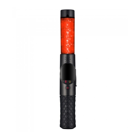
Status Pro T430 User manual

BA 1146 E
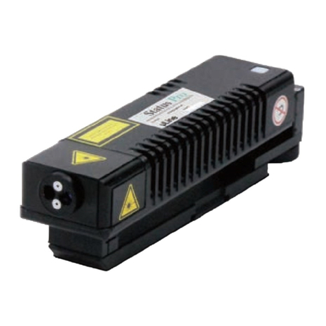
T430 Lasertransmitter
User Guide

2Status Pro – T430 User Guide
CONTENT
User Guide – English
Rotational Laser T430
(BG 832500)
We would like to congratulate you on the purchase of your Status Pro T430 Laser trans -
mitter. Before initial usage you should carefully read the safety instructions as well as the
user guidelines contained in this manual. We wish you every success when using this
measurement instrument.
Please note: User manuals can be amended when improvements or changes to the prod-
uct range have been carried out. Use the link below to make sure you have the most up to
date version of your user manual: www.statuspro.com.
Content
1. SAFETY INSTRUCTIONS . . . . . . . . . . . . . . . . . . . . . . . . . . . . . . . . . . . . . . . . . . . . . . . . . . . . . . . .4
1.1 Class of Laser . . . . . . . . . . . . . . . . . . . . . . . . . . . . . . . . . . . . . . . . . . . . . . . . . . . . . . . . . . . . . .4
1.2 Standards . . . . . . . . . . . . . . . . . . . . . . . . . . . . . . . . . . . . . . . . . . . . . . . . . . . . . . . . . . . . . . . . . .5
1.3 Advice on rechargeable cells . . . . . . . . . . . . . . . . . . . . . . . . . . . . . . . . . . . . . . . . . . . . . . . .5
1.4 Instrument Care . . . . . . . . . . . . . . . . . . . . . . . . . . . . . . . . . . . . . . . . . . . . . . . . . . . . . . . . . . . .6
1.5 Maintenance . . . . . . . . . . . . . . . . . . . . . . . . . . . . . . . . . . . . . . . . . . . . . . . . . . . . . . . . . . . . . . .6
1.6 Calibration and Repair . . . . . . . . . . . . . . . . . . . . . . . . . . . . . . . . . . . . . . . . . . . . . . . . . . . . . . .7
1.7 Liability Exclusion . . . . . . . . . . . . . . . . . . . . . . . . . . . . . . . . . . . . . . . . . . . . . . . . . . . . . . . . . . .7
2. GETTING STARTED . . . . . . . . . . . . . . . . . . . . . . . . . . . . . . . . . . . . . . . . . . . . . . . . . . . . . . . . . . . . .8
2.1 The T430 Keypad . . . . . . . . . . . . . . . . . . . . . . . . . . . . . . . . . . . . . . . . . . . . . . . . . . . . . . . . . . .8
2.2 Power Supply . . . . . . . . . . . . . . . . . . . . . . . . . . . . . . . . . . . . . . . . . . . . . . . . . . . . . . . . . . . . . .9
Rechargeable battery operation . . . . . . . . . . . . . . . . . . . . . . . . . . . . . . . . . . . . . . . . . . . . . .9
2.3 Setting up T430 . . . . . . . . . . . . . . . . . . . . . . . . . . . . . . . . . . . . . . . . . . . . . . . . . . . . . . . . . . .10
Position . . . . . . . . . . . . . . . . . . . . . . . . . . . . . . . . . . . . . . . . . . . . . . . . . . . . . . . . . . . . . . . . . . .10
2.4 Starting the T430 . . . . . . . . . . . . . . . . . . . . . . . . . . . . . . . . . . . . . . . . . . . . . . . . . . . . . . . . . . .11
2.5 Adjust the T430 . . . . . . . . . . . . . . . . . . . . . . . . . . . . . . . . . . . . . . . . . . . . . . . . . . . . . . . . . . . .12
Levelling . . . . . . . . . . . . . . . . . . . . . . . . . . . . . . . . . . . . . . . . . . . . . . . . . . . . . . . . . . . . . . . . . .12
2.6 Control via Infrared . . . . . . . . . . . . . . . . . . . . . . . . . . . . . . . . . . . . . . . . . . . . . . . . . . . . . . . .13

3
CONTENT
Status Pro – T430 User Guide
3. RC310 REMOTE CONTROL . . . . . . . . . . . . . . . . . . . . . . . . . . . . . . . . . . . . . . . . . . . . . . . . . . . . .13
3.1 Function keys on the RC310 . . . . . . . . . . . . . . . . . . . . . . . . . . . . . . . . . . . . . . . . . . . . . . . . .14
3.2 Display of the RC310 . . . . . . . . . . . . . . . . . . . . . . . . . . . . . . . . . . . . . . . . . . . . . . . . . . . . . . .14
Switching on . . . . . . . . . . . . . . . . . . . . . . . . . . . . . . . . . . . . . . . . . . . . . . . . . . . . . . . . . . . . . .14
Switching off . . . . . . . . . . . . . . . . . . . . . . . . . . . . . . . . . . . . . . . . . . . . . . . . . . . . . . . . . . . . . .14
3.3 Configuring the RC310 . . . . . . . . . . . . . . . . . . . . . . . . . . . . . . . . . . . . . . . . . . . . . . . . . . . . . .15
Configuration menu . . . . . . . . . . . . . . . . . . . . . . . . . . . . . . . . . . . . . . . . . . . . . . . . . . . . . . . .15
Reset function . . . . . . . . . . . . . . . . . . . . . . . . . . . . . . . . . . . . . . . . . . . . . . . . . . . . . . . . . . . . .16
3.4 Communication between the RC310 and the R310 Sensor . . . . . . . . . . . . . . . . . . . . . . .16
Laser position without controlling function . . . . . . . . . . . . . . . . . . . . . . . . . . . . . . . . . . . .16
Laser position with remote controlling of the T430 Laser . . . . . . . . . . . . . . . . . . . . . . . .16
Calibration command from the RC310 . . . . . . . . . . . . . . . . . . . . . . . . . . . . . . . . . . . . . . . .17
4. SIGNALS AND SPECIAL FEATURES . . . . . . . . . . . . . . . . . . . . . . . . . . . . . . . . . . . . . . . . . . . . .18
4.1 Power-LED . . . . . . . . . . . . . . . . . . . . . . . . . . . . . . . . . . . . . . . . . . . . . . . . . . . . . . . . . . . . . . . .18
4.2 Battery-LED (green) . . . . . . . . . . . . . . . . . . . . . . . . . . . . . . . . . . . . . . . . . . . . . . . . . . . . . . . .18
4.3 Battery-LED (red) . . . . . . . . . . . . . . . . . . . . . . . . . . . . . . . . . . . . . . . . . . . . . . . . . . . . . . . . . .18
4.4 Levelling-LED for X-/Phi-axis . . . . . . . . . . . . . . . . . . . . . . . . . . . . . . . . . . . . . . . . . . . . . . . .18
4.5 Levelling-LED für X-/Z-Achse . . . . . . . . . . . . . . . . . . . . . . . . . . . . . . . . . . . . . . . . . . . . . . . .19
4.6 LED’s around the Laser Aperture . . . . . . . . . . . . . . . . . . . . . . . . . . . . . . . . . . . . . . . . . . . . .19
Red (Y+)-LED . . . . . . . . . . . . . . . . . . . . . . . . . . . . . . . . . . . . . . . . . . . . . . . . . . . . . . . . . . . . . .19
Red (Y-)-LED . . . . . . . . . . . . . . . . . . . . . . . . . . . . . . . . . . . . . . . . . . . . . . . . . . . . . . . . . . . . . .19
Red (X+)-LED . . . . . . . . . . . . . . . . . . . . . . . . . . . . . . . . . . . . . . . . . . . . . . . . . . . . . . . . . . . . . .20
Red (X-)-LED . . . . . . . . . . . . . . . . . . . . . . . . . . . . . . . . . . . . . . . . . . . . . . . . . . . . . . . . . . . . . .20
Green (Y+)-LED . . . . . . . . . . . . . . . . . . . . . . . . . . . . . . . . . . . . . . . . . . . . . . . . . . . . . . . . . . . .20
Green (Y-)-LED . . . . . . . . . . . . . . . . . . . . . . . . . . . . . . . . . . . . . . . . . . . . . . . . . . . . . . . . . . . .21
Green (X+)-LED . . . . . . . . . . . . . . . . . . . . . . . . . . . . . . . . . . . . . . . . . . . . . . . . . . . . . . . . . . . .22
Green (X-)-LED . . . . . . . . . . . . . . . . . . . . . . . . . . . . . . . . . . . . . . . . . . . . . . . . . . . . . . . . . . . .22
5. TECHNICAL DETAILS . . . . . . . . . . . . . . . . . . . . . . . . . . . . . . . . . . . . . . . . . . . . . . . . . . . . . . . . . .23
6. ACCESSORIES . . . . . . . . . . . . . . . . . . . . . . . . . . . . . . . . . . . . . . . . . . . . . . . . . . . . . . . . . . . . . . . .24
7. PRODUCTS AND SERVICES . . . . . . . . . . . . . . . . . . . . . . . . . . . . . . . . . . . . . . . . . . . . . . . . . . . .28
Status Pro Services . . . . . . . . . . . . . . . . . . . . . . . . . . . . . . . . . . . . . . . . . . . . . . . . . . . . . . . . . . .29
Field Measurement . . . . . . . . . . . . . . . . . . . . . . . . . . . . . . . . . . . . . . . . . . . . . . . . . . . . . . . .29
Repair and Calibration . . . . . . . . . . . . . . . . . . . . . . . . . . . . . . . . . . . . . . . . . . . . . . . . . . . . . .29
Rental Services . . . . . . . . . . . . . . . . . . . . . . . . . . . . . . . . . . . . . . . . . . . . . . . . . . . . . . . . . . . .29
Seminars and Training . . . . . . . . . . . . . . . . . . . . . . . . . . . . . . . . . . . . . . . . . . . . . . . . . . . . . .29
8. NOTES . . . . . . . . . . . . . . . . . . . . . . . . . . . . . . . . . . . . . . . . . . . . . . . . . . . . . . . . . . . . . . . . . . . . . .30

4Status Pro – T430 User Guide
SAFET INSTRUCTIONS
1. Safety Instructions
1.1 Class of Laser
The laser light emitted from a Status Pro Laser has an output rating of < 1 0 mW.
The Laser is placed in the category „Class 2“ and is classified as safe for the use as a
measurement instrument. There are however a few safety aspects to be observed:
Caution!
• Do not stare into the laser beam.
• Do not point the laser beam at other people.
• Observe the local safety guidelines on site and if in doubt consult
the site safety engineer.
• Do not use the equipment in damp or moist locations.
• Ensure shading of the equipment against direct sunlight
or heat sources.
• Fluids or rain as well as extreme temperature conditions may
damage the equipment.
Note
Do not violently shake the laser or other sensors and always
protect against falls. This can damage the structure or the optics
of the instrument resulting in false measurements.
Do not touch rotating parts when in use!

5
SAFET INSTRUCTIONS
Status Pro – T430 User Guide
1.2 Standards
All Status Pro Laser and Receiver Instruments are developed and manufactured according
to the following CE Standards:
• EN 61000-6-3:2007
• EN 61000-6-2:2005
• EN 61000-4-2
• EN 61000-4-3
1.3 Advice on rechargeable cells
If the equipment is being stored for a longer period of time or being powered using mains
then the batteries should be removed to prevent damage of the instrument through leak-
age.
Consider information regarding the duration of a charge cycle and trickle charging.
Rechargeable cells can be recharged around 1000times when treated correctly but there
is no guarantee! Change the rechargeable cells when capacitance wanes.
Note
Help to protect the environment! Empty batteries do not belong
in the household waste disposal system. Only deposit empty or
damaged cells at a collection point specially designed for this
purpose.

6Status Pro – T430 User Guide
1.4 Instrument Care
Your measurement instrument is designed for use in an industrial environment and can
withstand water splashes or light spray as well as dust. Clean the equipment using a soft
cotton cloth and a mild soap solution. Laser apertures as well as sensor areas should only
be cleaned using a soft dry and dust-free cloth. Do not use paper towels to clean glass
surfaces as they could scratch. Avoid contact with grease oil or oil-based solutions when
handling the equipment.
1.5 Maintenance
The mechanical components of your equipment are prone to natural wear and tear! If the
instrument appears to have a technical defect contact the manufacturer.
Do not try to repair or open the sensor casing. Attempted repairs through unauthorized
personnel make the guarantee null and void! Always store the instrument under dry con-
ditions and use the case for transportation.
To ensure trouble-free processing simply fill in the form you will find using the following
link:
www.statuspro.com/doc/Formulare/FORM_RepairCalibration_1032_E.pd
Advice
To be able to identify the equipment when seeking advice always
quote the serial number of the equipment. The manufacturer does
not accept any responsibility for damage incurred through incorrect
maintenance carried out by non-authorized personnel.
SAFET INSTRUCTIONS

7
Status Pro – T430 User Guide
1.6 Calibration and Repair
To guarantee measurement accuracy and reliable operation of your
Status Pro Measurement System it is of utmost importance that the
recommended service intervals be adhered to. The system should be
checked for serviceability and re-calibrated by the Status Pro R&K-
Service every 12 months.
Within the scope of the service checks the complete system will also be
examined for possible wear or damage as well as receiving any software updates. The
date of the next service check for your equipment is stamped on the Status Pro calibration
sticker.
To ensure trouble-free processing of the service and calibration checks simply fill in the
form you will find using the following link:
www.statuspro.com/doc/Formulare/FORM_RepairCalibration_1032_E.pd
1.7 Liability Exclusion
The Status Pro GmbH does not accept responsibility for damage incurred through
incorrect use or handling of the equipment. To ensure correct usage a founded know -
ledge of the equipment is essential. It is of the utmost importance that you read and under-
stand the user guide!
No responsibility will be accepted for damage incurred through ignorance or disregarding
of the operating instructions.
SAFET INSTRUCTIONS

8Status Pro – T430 User Guide
GETTING STARTED
2. Getting started
2.1 he 430 Keypad
Laser aperture
(rotating beam)
Opening-button for
battery compartment
Infrared
receiver
Laser aperture
(static beam)
Keypad
Power button
Horizontal spirit level (coarse)
Vertical spirit level (coarse)
Self-levelling button
Bluetooth connection readout
Battery display

9
GETTING STARTED
Status Pro – T430 User Guide
2.2 Power Supply
Rechargeable battery operation
The T430 Rotational Laser operates with standard LI-Ion rechargeable batteries. One
charge cycles extend to 10 hours of measurement time.
It is necessary to charge the batteries on an extern charging station. The battery compart-
ment is located on the back side of the T430. Open the battery compartment by pressing
the button.
Note:
• Put rechargeable battery in according to direction of arrow
• Remove rechargeable battery if T430 is stored for a longer
period (risk of corrosion)

10 Status Pro – T430 User Guide
2.3 Setting up 430
Position
The T430 Laser depending on the task can be positioned vertically (upright) horizontally
(lying or prone) or at a freely selectable angle.
Upright Position
In the upright position the static beam is in the
vertical plane and the rotating beam is in the
horizontal plane.
Lying or prone position
In the prone position the static beam
is in the horizontal plane and the
rotating beam is in the vertical plane.
The T430 can be used without
additional equipment when being
used in the upright position. When
being used without attachments the
laser beam hits the receiver at
around 0 00 mm when R280 or R290
(with magnet adapter) is being used.
GETTING STARTED

11
Status Pro – T430 User Guide
The prone positioning is also possible
without any attachments.
2.4 Starting the 430
The narrow front side houses the necessary buttons to start the
T430 Rotational Laser.
Turn the T430 on by pressing the power button turn off by
pressing the button again.
Pressing the button once starts the rotation of the laser beam.
Pressing it again starts the levelling. Pressing the button
a third time stops the rotation and the levelling.
GETTING STARTED

12 Status Pro – T430 User Guide
2.5 Adjust the 430
Levelling
The T430 has different internal electronic spirit levels enabling the laser beam or plane to
be “aligned“ or levelled parallel to the earths gravitational “pull“.
Using this function a reference plane (laser plane) against which the measurement
object can be measured is quickly and easily established.
In the upright position the T430 is firstly adjusted roughly
by using the designated coarse spirit level.
After pressing the self-levelling button the rotational laser
plane will be adjusted exactly to level and according to
that the static beam will be exactly vertical.
Using the T430 in the prone position
the levelling process levels the static beam
and the rotational laser plane will be exactly vertical.
The automatic accomplishment of the levelling is
furthermore possible by using the setting layout of the
Launchpad software according to the special
measurement task. Another opportunity is to
use the button on the keypad of the T430.
GETTING STARTED

13
Status Pro – T430 User Guide
3. RC310 Remote Control
The RC310 is a remote control device with several functions.
Its primary use is to enable operation of the T430 without physically touching the laser
unit all functions of the T430 are possible using the RC310 except for turning on and off.
The RC310 can also be used for showing the measurement
value of a R310 reveiver if the sensor is at a distance from the
Laser. The measurement value from the R280 or R290 is trans-
mitted to the RC310 over infrared.
It is strongly recommended to work with the Launchpad soft-
ware instead of the RC310 Remote Control.
RC 310 REMOTE CONTROL
2.6 Control via Infrared
The T430 can receive commands via infrared and not
only by bluetooth. These signals can be sent using either
the RC310 Remote Control (see Chapt. 3) or using the
Receivers R280 or R290.
It is important that the infrared receiver can receive the
signals and consequently process them further.
When an R280 or R290 sends a command to the laser movement in the X or Y axis
depending on which has been selected will infrared be activated. The laser moves within
the axis until a value of 0 00 is reached. As long as infrared is active the laser will be cor-
rected to 0 00 should the value drift.

14 Status Pro – T430 User Guide
RC 310 REMOTE CONTROL
3.1 Function keys on the RC310
Power button on / o and
Sel -levelling on / o
Turn on the RC310 by pressing the power button.
When the RC310 is in operation the self-levelling function of the T430 Laser can be turned
on or off by pressing the power button. If the power button is pressed and held for longer
than 1 5 seconds the RC310 will be switched off.
(Note: If the RC310 is pointing in the direction of the IR opening on the T430 Laser the
Levelling function could be turned on or off unintentionally).
Laser rotation on / o
By pressing this button the T430 Laser rotation can be activated or deactivated.
Arrow buttons or aligning the laser plane
The position of the laser beam/plane can be adjusted in the X- and
Y-Axes (▲(+) / ▼(-) / (+) / (-)) without physically touching the Laser.
3.2 Display of the RC310
Switching on
The RC310 is turned on by pressing the lower right hand
button. The following information will be displayed for a
duration of ca. 1 second: company name instrument name
and the software version.
Afterwards an image of all of the buttons is displayed as
well as the software version this is the standard screen
for operation.
Switching o
To turn the RC310 off simply press the power button for at
least 1 5 seconds. A “reminder tone” signalises the operator
to release the button if held pressed!
▲
▲
O f f . . .

15
Status Pro – T430 User Guide
3.3 Configuring the RC310
To enter the configuration menu press and hold the ▼button then press the ▲button
as well.
Change settings: ▼ and ▲ buttons
Change menu level: and buttons
When moving from one menu level to another the previous settings will be saved to mem-
ory. After reaching the last level in the menu the RC310 returns to normal operational
mode (Menu Exit).
The configuration includes the setting of the language (German English and French)
the setting of the unit of measurement (metric anglo-saxon) the contrast and the switch-
off time. In addition the software version the internal checksum the battery voltage and
temperature are displayed as well.
Con iguration menu
Language: German English and French
Units: mm or inch
Display contrast: 0 - 63
Auto turn-off time: 2 – 240 min / Off
Instrument information: software version internal check
sum battery level and temperature
▲
▲
RC 310 REMOTE CONTROL
L a n g u a g e : E n g l .
U n i t : m m
C o n t r a s t : 4 0
T u r n o f f : 1 0 m i n

16 Status Pro – T430 User Guide
Reset unction
The reset function returns the RC310 to its factory settings. (Language: German;
Units: metric; Contrast: 40; Auto-off time: 10min).
To return the RC310 to its factory settings press the ▲buttons in the order shown
and keep pressed.
3.4 Communication between the RC310 and the
R310 Sensor
There are three kinds of signal that can be sent from the R310 to the RC310:
Laser position without controlling unction
In this mode the position value or measurement value on the R310 is transmitted to the
RC310 providing the R310 is set to RC310 in the menu and the IR button on the R310 has
been activated.
Laser position with remote controlling o the T430 Laser
When the remote controlling of a particular axis has been selected from the R310 menu
the position of the laser beam will be moved accordingly. Additionally the measurement
value will be transmitted to the RC310 along with the axis being presently controlled. The
values shown on the R310 can differ slightly from the value being displayed by the RC310
as the values for the laser positioning are evaluated slightly differently.
Again to achieve laser positioning of the T430 Laser and obtain values on the RC310 the
infra-red on the R310 must be activated.
▲
▲
RC 310 REMOTE CONTROL

17
Status Pro – T430 User Guide
The RC310 receives and displays a new value every 500ms signalised by a “click”.
Calibration command rom the RC310
For Information only when the R310 has sent a command to the T430 for re-calibration
the axis which has been calibrated will be shown in the RC310 display.
Please observe the ollowing:
• To ensure trouble-free operation ensure that nothing obstructs the line of sight
between RC310 and its receiving instrument
• “Point” the RC310 in the direction of its receiving instrument
• If the remote distance range is drastically reduced replace the battery as a first
action. To do this remove the RC310 from its protective rubber casing then open the
battery cover on the reverse side of the housing. The battery is a 9-Volt block battery
• The maximum operating range of the RC310 is 50 metres
• The R310 can only send a signal when a laser beam is being measured
• When an IR signal is interrupted the last received value will be displayed for
approx. 2 seconds
RC 310 REMOTE CONTROL
1 . 2 3 m m X - A x i s 3 . 2 1 m m Y - A x i s

18 Status Pro – T430 User Guide
SIGNALS AND SPECIAL FEATURES
4. Signals and Special
Features
4.1 Power-LED
4.2 Battery-LED (green)
4.3 Battery-LED (red)
4.4 Levelling-LED for X-/Phi-axis
Permanently lit Laser is turned on no errors•
5Hz-Flash
Error •
(Power problem boot sector error end of position
reached ...)
Power-On- / Power-Off-Sequence•
Permanently lit Supply voltage sufficient•
5Hz-Flash Power-On- / Power-Off-Sequence•
1Hz-Flash Supply voltage below minimum threshold•
Permanently lit Axis is in levelling mode•
5Hz-Flash Power-On- / Power-Off-Sequence•
Levelling not possible outside of measurement range•
1Hz-Flash Temperature drift too large (usually during warm-up) – WAIT•
5Hz-Flash Power-On- / Power-Off-Sequence•

19
SIGNALS AND SPECIAL FEATURES
Status Pro – T430 User Guide
4.5 Levelling-LED für X-/Z-Achse
4.6 LED’s around the Laser Aperture
Red (Y+)-LED
Red (Y-)-LED
Permanaently lit Axis is in levelling mode•
5Hz-Flash Power-On- / Power-Off-Sequence•
Levelling not possible outside of measurement range•
1Hz-Flash Temperature drift too large (usually during warm-up) – WAIT•
Permanently lit Laser is being moved in the Y+ direction•
Calibration of Y- successful•
5Hz-Flash
Calibration could not be conducted•
Limiter for the Y-axis has been triggered (the end of position or•
the travel range has been reached or cannot be exited)
Short pulses Single steps in direction of Y+•
Permanently lit Laser is being moved in the Y+ direction•
Calibration of Y- successful•
5Hz-Flash
Calibration could not be conducted•
Limiter for the Y-axis has been triggered (the end of position or•
the travel range has been reached or cannot be exited)
Short Pulses Single steps in direction of Y-•
Y+
Y-

20 Status Pro – T430 User Guide
Red (X+)-LED
Red (X-)-LED
Green (Y+)-LED
Permanently lit Laser is being moved in X+ direction•
Calibration of X+ successful•
5Hz-Flash
Calibration could not be conducted•
Limiter for the X-axis has been triggered (the end of position or•
the travel range has been reached or cannot be exited)
Short pulses Single steps in direction of X+•
Permanently lit Laser is being moved in X- direction•
Calibration of X- successful•
5Hz-Flash
Calibration could not be conducted•
Limiter for X-axis has been triggered (the end of position or the•
travel range has been reached or cannot be exited)
Short pulses Single steps in direction of X-•
X+
X-
Permanently lit
Levelling: Y-axis is levelled•
Calibration of Y-axis successful•
2-Sensor-Control:•
Y-axis completely arranged target position reached
5Hz-Flash
Levelling: Y-axis is more than 1000 steps away from calibrated•
levelling value
Levelling: Y-(Z-)axis displays restive values•
Levelling not possible outside measurement range•
2-Sensor-Control:•
Y-axis is more than 5 steps away from target position
Y+
SIGNALS AND SPECIAL FEATURES
Table of contents
Other Status Pro Measuring Instrument manuals
Popular Measuring Instrument manuals by other brands

Rhopoint Instruments
Rhopoint Instruments MFFT-90 instructions
Velleman
Velleman WS8461 user manual
Laser Technology
Laser Technology TruPulse 200X user manual
Bacharach
Bacharach Leakator Jr. Instruction
Sylvac
Sylvac Bowers XTL operating instructions

Denver Instrument
Denver Instrument IR-35 operating instructions
