Status Pro Belt Tension Pro User manual
1
OPERATING INSTRUCTIONS
BELT TENSION MEASUREMENT SYSTEM
VERSION 2.2

2
Table of contents
Introduction .............................................................................. 3
Safety guidelines ...................................................................... 3
Notes on batteries/Rechargeable batteries.................................... 4
Instructions on caring for the instrument ...................................... 5
Maintenance ........................................................................ 5
Disclaimer .............................................................................. 5
Intended use ........................................................................... 6
Delivered items ....................................................................... 6
Product advantages................................................................... 6
Preparation measures ................................................................... 7
Connecting the measurement probe ............................................... 7
Operational elements ................................................................... 8
Overview ............................................................................... 8
Operating buttons..................................................................... 9
Operation ................................................................................10
General information on "belt tension“ ...........................................10
Measuring the belt span tension ................................................10
Measuring the belt tension .........................................................11
Measurement procedure ............................................................... 12
Checking the measurement probe – Frequency test............................12
Notes on positioning the measurement probe...................................13
Measurement step ...................................................................13
Measurement evaluation, green-yellow-red .....................................14
Storing measurements............................................................... 15
Procedure: ......................................................................... 15
Calling up stored measurements ..................................................15
Procedure: ......................................................................... 15
Switching off the instrument.......................................................15
PC-Software belt database (optional) ...............................................16
Belt Tension Pro PC-Software (optional) .........................................17
Appendix .................................................................................18
Specifications.........................................................................18
Menu structure .......................................................................19
Manufacturer data......................................................................20

3
INTRODUCTION
Thank you for choosing your new Status Pro measurement system - the Belt
Tension Pro.
We hope to be able to fulfill your expectations of this modern measurement
system.
Before making any measurements, be sure to read and follow the safety
guidelines and precautionary measures.
We wish you great success in using your new measurement system
SAFETY GUIDELINES
The Belt Tension Pro uses an extra bright, red LED (660 nm). For this reason,
it is not necessary to take measures to protect your eyes. However, do not
look directly into the bright measurement beam at close range.
Consider the following safety precautions.
Caution
Before making measurements, ensure that the instrument is switched off
(master switch) and secured against unintentional restarting.
• Personnel must be informed in a timely manner that measurements will
be performed.
• If necessary, clearly mark and cordon off the service area at or around the
machine, for example, by using lines or ropes.
• The measuring and setting of the belt tension must only be performed by
qualified, instructed technical staff while following the specific instruction
manual for the instrument as well as the extended documentation from
the supplier.
Caution
This instrument must not be operated in rooms with high humidity.Avoid
direct exposure to heat, for example, through sunlight. Moisture and rain, as
well as extreme heat or cold, will damage the instrument.
Note
Do not let the instrument drop or be bumped sharply. The delicate optic
s
could be damaged and the measurements made unusable.
Caution
For connecting the BeltTension Pro to a PC, only use the special BG 810000
cable. If a normal RS232 cable is used, the instrument can be damaged.

4
Notes on batteries/rechargeable batteries
If the instrument is not to be used for a long period of time, then the battery
/rechargeable battery must be removed. Otherwise, there is a risk of
discharging or ruining the battery/rechargeable battery, and consequently
damaging the instrument.
Caution
Regular batteries must not be recharged, heated, or disposed of in an open
flame (explosion hazard!).
Note
Please contribute to the protection of the environment.
Discharged batteries and rechargeable batteries should not be disposed of
along with household waste.They can be taken to collection sites for used
batteries or special waste.
Find out where these sites are located.
At the end of its service life, this product must not be
disposed of along with normal waste but must be taken to a
collection site for the recycling of electrical and electronic
devices.
The materials can be reused according to how they are
labeled. By recycling, reusing the materials or other forms of
reusing old equipment, you will make an important
contribution to the protection of our environment.

5
Instructions on caring for the instrument
The Belt Tension Pro has been developed for industrial use and is protected
against sprayed water and dust in accordance with IP55; the measurement
probe is protected in accordance with IP66. For cleaning the housing, a soft
cloth, with mild soapy water if necessary, should be used; the detector
surface should only be cleaned with alcohol.
When cleaning the detector surface of the measurement probe, do not use
paper towels or materials that could scratch the detector surface. For
optimal operational conditions, the detector surface as well as the
connections should be protected from becoming soiled or, for example, from
coming into contact with oil or grease.
Maintenance
In case of any malfunction, contact the manufacturer. Do not open the
instrument yourself.
The warranty will expire if unauthorized persons attempt to repair or
otherwise tamper with the instrument.
Storage must always take place under dry conditions.
Transport the instrument only in its original case.
Note
The manufacturer assumes no responsibility for damages that arise as result
of improper maintenance or repair work by third parties.
DISCLAIMER
Status Pro GmbH is not liable for damages that arise as a result of improper
use. Knowledge of this handbook is also part of proper use. For this reason,
strictly follow the instructions in this handbook and in the technical
documents for the sensors. We can not be liable for errors that arise due to
not following the operating instructions.

6
INTENDED USE
•The Belt Tension Pro is a precision measuring instrument for
measuring the belt tension and rotary speed of industrial machines
and units.
Note
The Belt Tension must only be used for the purposes specified above.
Unintended usage, use of unsuitable components, or modifications in
regard to intended use can lead to malfunctions in operation for which
Status Pro GmbH assumes no liability.
DELIVERED ITEMS
This Belt Tension Pro measurement instrument is delivered in a durable
plastic case. A measurement probe and a 9 V battery are also supplied.
PRODUCT ADVANTAGES
• Precise measurement of belt tension
• Precise measurement of rotary speed
• Precise calculation of belt span tension
• Built-in frequency test for checking the measurement probe
• Required for recording in accordance with DIN EN ISO 9001ff
• Operational guidance and readout of measured values in a choice of 3
languages
• Simple and reliable operation
• Compact and handy design, rubber-coated for protection
7
PREPARATION MEASURES
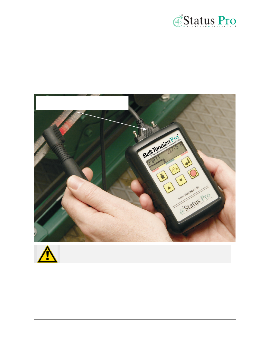
CONNECTING THE MEASUREMENT PROBE
Remove the measurement probe from its case, insert the measurement probe
connector into the socket on the Belt Tension Pro. Secure the connector by
tightening both screws.
Caution
Do not over tighten the two screws.
Measurement probe

8
OPERATIONAL ELEMENTS
OVERVIEW
The operating buttons in “1” control various functions. The display in “2”
shows settings and measurement results. The measurement probe “3”
registers the characteristic frequency of the tensioned, free belt by using
pulsed light or the rotary speed, and communicates the measurement values
to the Belt Tension Pro.
Belt Tension Pro Overview
1. Operating buttons
2. Display
3. Measurement probe
1
2
3

9
OPERATING BUTTONS
The operating buttons control various functions.
1. ON/OFF switch or storage of measurements
2. ENTER
3. Strand length
4. Belt mass or belt type selection; in the storage mode,
readout of measurement results
5. Arrow c: Change values - increase
6. Arrow d: Change values - decrease
1
2
3
4
5, 6

10
OPERATION
Operating the Belt Tension Pro is simple and straight forward.
GENERAL INFORMATION ON "BELT TENSION“
Measuring the belt span tension
To calculate the belt span tension or trum force, the measured values of the
belt tension, the belt mass and the belt length are input. The calculated trum
force is compared with the nominal value that is defined during the design of
the drive.
The trum force is calculated using the following formula:
F = 4 • m • L2• f2
In this formula,
F = trum force in N
m = belt mass per unit length in kg/m
L = length of the free belt strand in m
f = measured characteristic frequency of the free belt in Hz
11
MEASURING THE BELT TENSION
The belt tension can only be measured when the drive is switched off and
stopped.
Caution
Before making measurements, ensure that the machine is switched off
(master switch) and secured against unintentional restarting.
The installed and tensioned drive belt is set into natural oscillation with a
short impulse or by striking it lightly.
This static characteristic frequency is measured by the probe by using light
pulses. There must be a sufficient amount of light reflected from the belt.
By using the measured data along with the mass of the belt and the length of
the free belt strand (from the integrated belt database, for example) the Belt
Tension Pro calculates the trum force.
The readout of the measured values takes place according to the settings; for
example, frequency in Hertz or force in Newtons.

12
MEASUREMENT PROCEDURE
Please follow the instructions below. This will ensure that the measured
values are correct and will avoid erroneous measurement results.
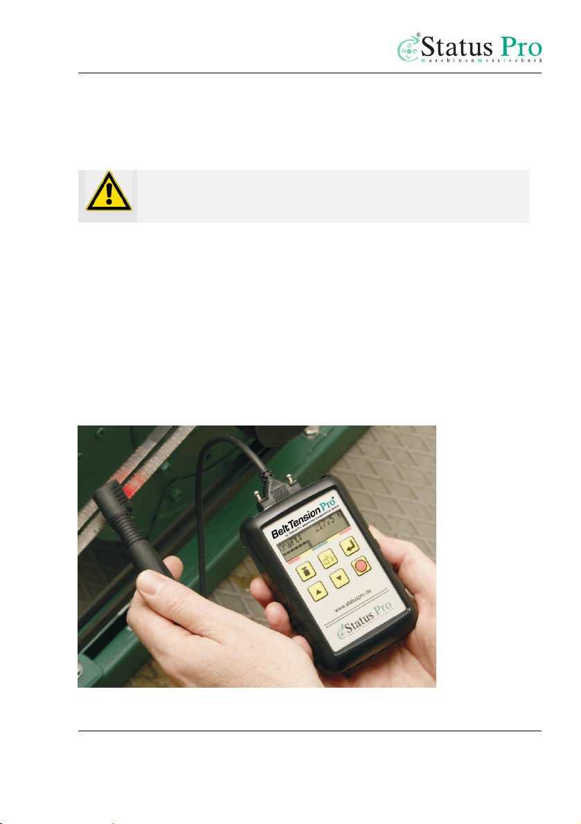
CHECKING THE MEASUREMENT PROBE –FREQUENCY TEST
Built into the Belt Tension Pro software is an important and useful additional
function for checking the measurement probe, for example, before making a
measurement, see p. 18. During this "self-test", the Belt Tension Pro outputs a
nominal frequency of 25 Hz over the display. That is, the illumination of the
display is switched off and on at a frequency of 25 Hz. If it is functioning
properly, the measurement probe must readout this 25 Hz in the display. The
readout can vary in the range from 24.7 Hz to 25.3 Hz.
1. Switch on the Belt Tension Pro using the ON/OFF 1 button.
2. Switch to the "Freq-Test" using the ENTER button; see "Menu structure", p. 19.
3. Using the d/cbutton, switch on the frequency test; the display begins to
"flicker" at a nominal frequency of 25 Hz.
4. Hold the measurement probe up close to the display.
5. The measurement probe measures the display frequency; the result is indicated
in the display below on the right; an acoustic signal is output if the
measurement is successful.
Note
If the result deviates from the nominal value of 25 Hz (readout in display: 24.
7
– 25.3 Hz), then check the cables as well as the battery voltage.
If in doubt, contact the manufacturer.
6. Using the d/cbutton, switch off the frequency test; switch to the
measurement mode using ENTER.
13
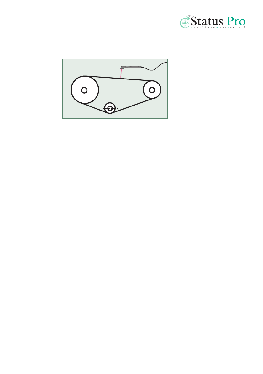
NOTES ON POSITIONING THE MEASUREMENT PROBE
The distance between the drive belt and the measurement probe should be
between 3 - 20 mm. The measurement of the belt tension should take place
at the longer strand of the belt, in the middle between the two drive rollers.
MEASUREMENT STEP
1. Switch on the Belt Tension Pro using the ON/OFF 1 button. The instrument is
ready for taking measurements.
2. Input the belt strand length and belt mass, see "Menu structure" p. 19.
3. Alternatively, select the belt data from the implemented belt database, see the
next page.
4. Set the drive belt into natural oscillation by striking it.
5. Hold the measurement probe over the drive belt at approximately the center of
the free belt span length. The distance from the belt can be between 3 and 20
mm.
6. In the display, the readout is in Newtons or Hertz. A successful measurement is
acknowledged by a longer acoustic signal.
7. If the measurement is invalid, then the message "Instab“ appears in the display;
a short acoustic signal sounds.
8. Check the setup and repeat the measurement.
9. The measured value is displayed (in Hz or N).

14
MEASUREMENT EVALUATION,GREEN-YELLOW-RED
When using the Belt Tension Pro, you will only be provided with a raw
measurement result, for example, the force in "Newtons". You can evaluate
the measurement results directly by using the indicator bar as well as the
green-yellow-red markings below the display:
The position (trend) of the indicator bar indicates if the measured values lie
below (left, belt too loose) or above (right, belt too tight) the nominal
values.
In the above example, the result is in the green area (measured value OK);
the trend shows that the force is tending more to be too small than to be too
large.
In addition, an evaluation of the measurement result is shown in the display
using distinct symbols (to the right, near the measured value):
√: = Good
+: = Acceptable
-: = Bad
Status bar with markings:
green: OK, within tolerance
yellow: result is close to tolerance
red: bad measurement result

15
STORING MEASUREMENTS
For documentation purposes, you may store the measurements that have
been made in the instrument. The instrument has internal storage for up to
255 measurements. Using the optional Belt Tension Pro PC-Software,
convenient options are available for producing measurement data reports.
Procedure:
1. Measurement performed, measured value is displayed.
2. Press button ²"ON/OFF“ 1, Storage No. X appears in the display.
3. Using TSarrow buttons 5, 6, select Storage No.
4. Confirm with ENTER, Store? appears in the display.
5. Confirm with ENTER OK or cancel using button ²"Store“ 1 Esc.
6. After storing, the message Stored in X appears in the display.
CALLING UP STORED MEASUREMENTS
You may call up measurements stored in the instrument at any time.
Procedure:
1. Press button ²"ON/OFF“ 1, Storage No. X appears in the display.
2. Using TSarrow buttons 5, 6, select Storage No.
3. Press button 4; the measurement result appears in the display.
4. If necessary, select an additional Storage No. using TSarrow buttons 5, 6 and
display using button 4.
5. To end, press button ²"ON/OFF“ 1 twice.
SWITCHING OFF THE INSTRUMENT
•Press ²ON/OFF and hold down until Off… appears in the display.

16
PC-SOFTWARE BELT DATA BASE (OPTIONAL)
There are approx. 200 data records for common standard drive belts in the
Belt Tension Pro software.
This facilitates the input of necessary belt data.
Note
Please consult the continually updated belt database at
www.statuspro.de.
1. Switch on the Belt Tension Pro.
2. Press button 4 to input the mass of the belt, see Overview p. 9 as well as "Menu
structure" p.19“.
3. Press button 4 again; now, using the T/Sbuttons, select the belt data from
the implemented PC-Software belt database.
4. Acquire the belt data using the ENTER button.
5. The instrument is now ready for making measurements.

17
BELT TENSION PRO PC-SOFTWARE (OPTIONAL)
The associated PC-Software facilitates the use of the Belt Tension Pro in
practice, and serves to evaluate measurements that have been made. In
addition, you can easily manage the belt database and customize it through
updates.
See the accompanying documentation entitled "Belt Tension Pro PC-
Software“.
Caution
For connecting the Belt Tension Pro to a PC, only use a special BG
810000 cable.
If a regular RS232 cable is used, the instrument can be damaged.

18
APPENDIX
SPECIFICATIONS
SP BELT-PRO:
Measurement range 1 - 500 Hz
Modulation 5 kHz
Sensor test 25 Hz with OK message
Readout error +/- 0.3 Hz
Resolution +/- 0.1 Hz
Operation -20°...+85°C; -68°...+185° F
Storage -40°...+105°C; -40°...+221°F
Humidity 20 .. 95 %
Housing plastic (PVC); IP20
Measurement sensor plastic; IP66
Housing dimensions WxHxD 75 x 115 x 35 mm; 2.95 x 4.53 x 1.38 inches
Carrying-case dimensions 230 x 220 x 75 mm; 9.06 x 8.66 x 2.95 inches
Display 2 line LCD 12 x 60 mm (0.47 x 2.36 in) with
background illumination
Languages language selection for three languages
Input limits free belt strand: 30 - 9,999 mm
Input limits belt mass: 0.001 - 9.999 kg/m
Number of storage locations 255
Voltage supply 9 V alkaline battery, type E-Block 6LR61
Interface RS232, DSUB9

19
MENU STRUCTURE
Set strand length
using arrow buttons
UP/DOWN
Display
Hz/N/rpm menu option
Language option
Measurement
Mode
Units option
Sensitivity
Backlight
Frequency test
System status
Contrast
Set belt mass
using arrow buttons
UP/DOWN
Safety
enquiry
Value saved,
message displayed
Saved value
shown in
display
Belt type displayed
Set belt type
using arrow buttons
UP/DOWN
Set display type
using arrow buttons
UP/DOWN
Hz, N, rpm
and press ENTER
Set language
using arrow buttons
UP/DOWN
Germ., French, Engl.
and press ENTER
Set units using arrow
buttons UP/DOWN
mm, inch
and press ENTER
Set sensitivity using arrow
buttons UP/DOWN
Value 1 ... 50
(1 = highest sens.,
50 = lowest sens.)
Set display contrast
using arrow
buttons UP/DOWN
Value 24 ... 63
and press ENTER
Set backlight ON/OFF
using arrow
buttons UP/DOWN
and press ENTER
Set frequency test ON/OFF
using arrow
buttons UP/DOWN
and press ENTER
Overview
Version
Battery capacity
Temperature
Belt type 0 set
or no belttypes saved
Set memory No.
using arrow buttons
UP/DOWN
At the lower left in the display of the Belt Tension Pro, each active function
key appears superimposed on the corresponding menu item.

20
MANUFACTURER DATA
Publication No. HB 135E
3rd edition, August 2010
Copyright 2010
Status Pro Maschinenmesstechnik GmbH
Mausegatt 19
De-44866 Bochum
All rights reserved. This handbook or parts thereof may not be copied or
reproduced in any other manner without the prior consent of Status Pro
GmbH. The technical accuracy and completeness remain reserved and can be
changed without notification. Comments on any errors in this handbook are
welcome at any time.
www.statuspro.de
Table of contents
Other Status Pro Measuring Instrument manuals


Popular Measuring Instrument manuals by other brands


AEMC
AEMC A196-24-BK user manual

Delmhorst
Delmhorst F-2000R Operation manual

AYTU BioSience
AYTU BioSience mioxsys user manual

PCB Piezotronics
PCB Piezotronics IMI SENSORS EX602D01 Installation and operating manual

Datalogic
Datalogic VLASE IR 1109-1 42 Series user manual

Keysight
Keysight N432A Service guide