Status Pro T250 User manual

T250
Laser transmitter
Instruction manual
Another fine solution by

2
T250
Status Pro – T250 Instruction manual
CONTENTS
Instruction manual – English
Laser transmitter T250
(SP T250-P)
We woul like to congratulate you on the purchase of your Status Pro R310 Laser receiver.
Before initial usage you shoul carefully rea the safety instructions as well as the user
gui elines containe in this manual. We wish you every success when using this
Measurement Instrument.
Please note: User Manuals can be amen e when improvements or changes to the prouct
range have been carrie out. Use the link below to make sure you have the most up to
ate version of your User Manual. www.statuspro.co / achine_geo etry/docu ents/
Contents
1. SAFETY INSTRUCTIONS . . . . . . . . . . . . . . . . . . . . . . . . . . . . . . . . . . . . . . . . . . . . . . . . . . . . . . . . 3
1.1 Class of laser . . . . . . . . . . . . . . . . . . . . . . . . . . . . . . . . . . . . . . . . . . . . . . . . . . . . . . . . . . . . . 3
1.2 Stan ar s . . . . . . . . . . . . . . . . . . . . . . . . . . . . . . . . . . . . . . . . . . . . . . . . . . . . . . . . . . . . . . . . 4
1.3 Instrument care . . . . . . . . . . . . . . . . . . . . . . . . . . . . . . . . . . . . . . . . . . . . . . . . . . . . . . . . . . 4
1.4 Maintenance . . . . . . . . . . . . . . . . . . . . . . . . . . . . . . . . . . . . . . . . . . . . . . . . . . . . . . . . . . . . . 4
1.5 Calibration . . . . . . . . . . . . . . . . . . . . . . . . . . . . . . . . . . . . . . . . . . . . . . . . . . . . . . . . . . . . . . . 5
1.6 Liability Exclusion . . . . . . . . . . . . . . . . . . . . . . . . . . . . . . . . . . . . . . . . . . . . . . . . . . . . . . . . . 5
2. GETTING STARTED . . . . . . . . . . . . . . . . . . . . . . . . . . . . . . . . . . . . . . . . . . . . . . . . . . . . . . . . . . . . . 6
2.1 Power supply . . . . . . . . . . . . . . . . . . . . . . . . . . . . . . . . . . . . . . . . . . . . . . . . . . . . . . . . . . . . . 6
2.2 Assembly . . . . . . . . . . . . . . . . . . . . . . . . . . . . . . . . . . . . . . . . . . . . . . . . . . . . . . . . . . . . . . . . 7
3. OPERATION . . . . . . . . . . . . . . . . . . . . . . . . . . . . . . . . . . . . . . . . . . . . . . . . . . . . . . . . . . . . . . . . . . . 8
3.1 Aligning the laser beam . . . . . . . . . . . . . . . . . . . . . . . . . . . . . . . . . . . . . . . . . . . . . . . . . . . 8
3.2 Setting up the T250 for straightness measurements . . . . . . . . . . . . . . . . . . . . . . . . . . 10
4. TECHNICAL DETAILS . . . . . . . . . . . . . . . . . . . . . . . . . . . . . . . . . . . . . . . . . . . . . . . . . . . . . . . . . . 12
5. ACCESSORIES . . . . . . . . . . . . . . . . . . . . . . . . . . . . . . . . . . . . . . . . . . . . . . . . . . . . . . . . . . . . . . . .13
6. PRODUCTS AND SERVICE . . . . . . . . . . . . . . . . . . . . . . . . . . . . . . . . . . . . . . . . . . . . . . . . . . . . . 15

Status Pro – T250 Instruction manual 3
SAFETY INSTRUCTIONS
1. Safety Instructions
1.1 Class f Laser
The laser light emitte from a Status Pro Laser has an Output Rating of < 1,0 mW.
The Laser is place in the category „Class 2“ an is classifie as safe for the use as a
Measurement instrument. There are however a few safety aspects to be observe :
Cauti n!
•Do not stare into the laser beam.
•Do not point the laser beam at other people.
•Observe the local safety gui elines on Site an if in oubt consult
the Site safety Engineer.
•Do not use the equipmentin amp or moist locations.
•Ensure sha ing of the equipment against irect sunlight or heat
sources.
•Flui s or rain as well as extreme temperature con itions may
amage the equipment.
N te
Do not violently shake the Laser or other sensors an always
protect against falls. This can amage the structure or the optics
of the instrument resulting in false measurements.
Do not touch rotating parts when in use!

4
T250
Status Pro – T250 Instruction manual
SAFETY INSTRUCTIONS
1.2 Standards
All Status Pro Laser an Receiver Instruments are evelope an manufacture
accor ing to the following CE Stan ar s:
•EN 55 011
•EN 55 022
•EN 61 000-4-2
•EN 61 000-4-3
•EN 60 335
1.3 Instrument care
Your measurement instrument is esigne for use in an in ustrial environmentan can
withstan water splashes or light spray as well as ust. Clean the equipment using a soft
cotton cloth an a mil soap solution. Laser apertures as well as well as sensor areas
shoul only be cleane using a soft, ry an ust-free cloth. Do not use paper towels to
clean glass surfaces as they coul scratch. Avoi contact with grease, oil or oil-base
solutions when han ling the equipment..
1.4 Maintenance
The mechanical components of your equipment are prone to natural wear an tear! If the
Instrument appears to have a technical efect, contact the Manufacturer. Das Gerät nicht
eigenstän ig öffnen. Attempte repairs through unauthorise personnel makes the gua-
rantee null an voi !
Always store the equipment un er ry con itions an use the case for transportation.
N te
To be able to i entify the equipment when seeking a vice always
quote the serial number of the equipment. The Manufacturer oes
not accept any responsibility for amage incurre through incorrect
maintenance carrie out by non-authorise personnel.

Status Pro – T250 Instruction manual 5
SAFETY INSTRUCTIONS
1.5 Calibrati n
To guarantee measurement accuracy, an reliable operation of your
Status Pro Measure ment System, it is of utmost importance that the
recommen e Service Intervals be a here to. The System shoul be
checke for serviceability, an recalibrate by the Status Pro workshops
every 12 months.
Within the scope of the service checks, the complete system will also be examine for
possible wear or amage, as well as receiving any software up ates. The ate of the next
service check for your equipment is stampe on the Status Pro calibration sticker.
To ensure trouble-free processing of the service an calibration checks, simply use
the form you will fin using the following link:
www.statuspro.co / achine_geo etry/service_support/calibration_repair/
1.6 Liability Exclusi n
The Status Pro GmbH oes not accept responsibility for amage incurre through incor-
rect use or han ling of the equipment. To ensure correct usage, a foun e knowle ge of
the equipment is essential. It is of the utmost importance that you rea an un erstan the
Han book!
No responsibility will be accepte for amage incurre through ignorance or isregar ing
of the operating instructions.
6
T250
Status Pro – T250 Instruction manual
GETTING STARTED
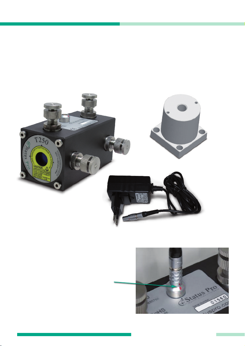
2. Getting starte
The T250 Laser transmitter package (SP T250-P) comprises of the T250 Laser transmitter
(I - BG 830750), a mains power supply cable (III - BG800025), an an A apter (II - 832050)
enabling mounting of the T250 Laser when using a tripo , or when using the Borealign Kit
(SP BOREALIGN).
2.1 P wer supply
To operate the T250, connect the power
supply cable to the mains, an to the
socket on the T250 housing.
Ensure that the re markings on the plug
an the socket are correctly aligne .
This ensures correct polarity.
II: A apter
III: Power
supply cableI: Laser
transmitter T250

Status Pro – T250 Instruction manual 7
GETTING STARTED
2.2 Assembly
To use the T250 with a tripo , fasten the A apter (II) to the holes on the lower face of the
housing (V) using four of the screws elivere (IV). When elivere , the T250 will have
four screws on the front an the back facing.
The cylin rical face of the a apter has a 5/8“ threa for use with a tripo fitting.
To enable mounting on a vertical surface or for use with the Borealign kit, the A apter (II)
can be fitte to the front or the rear facing, again using the supplie screws. The 5/8”
threa is continuous, so the laser beam has sight through the A apter (II).
IV IV
II
II
V
8
T250
Status Pro – T250 Instruction manual
OPERATION
3
2
1
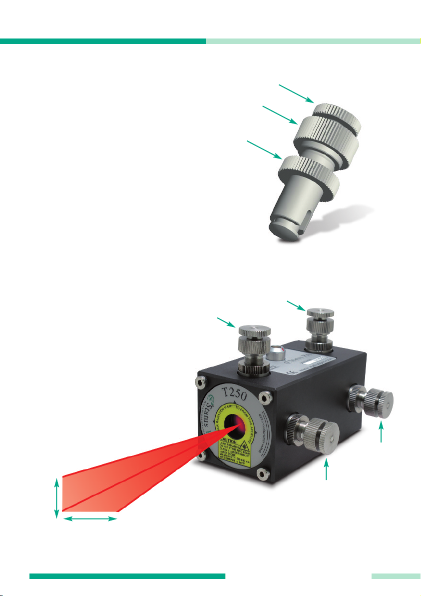
3. Operation
3.1 Aligning the laser
beam
There are four a justing screw assemblies
in the housing of the T250 enabling align -
ment of the laser beam. Each of these
assemblies comprises of a fine a justment
screw (1), a coarse a justment screw (2),
an a locking nut for the coarse a justment
screw (3).
To roughly a just the laser beam, loosen
the locking nut, align the laser beam with
the coarse screw (2) an the tighten up the
locking nut again. Fine a justment is
carrie out with locking nut tightene up.
When the T250 is in the horizontal position
(see below) the two screws on the upper
si e (Y1 & Y2) are use to align the laser
beam vertically.
The two screws on the si e (X1 & X2)
are use for the horizontal align ment of
the laser beam.
Y 1
X 1
X 2
Y 2
∆Y
∆X
Status Pro – T250 Instruction manual 9
OPERATION
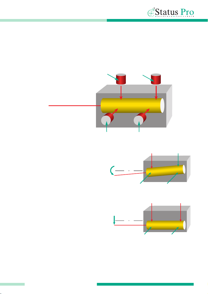
Simply explaine , the laser beam of the T250 is house in a tube. Four screws are
attache to this tube, two on the si e an two on top. This arrangement enables alignment
of the laser angle as well as the parallel shift in both the vertical an the horizontal plane.
Example:
1) If the Y1 screw is move ownwar s
(screwe in) then the angle of the laser
beam will also slope ownwar s
2) If both Y1 an Y2 are move ownwar s
(screwe in) then the laser laser beam will
move parallelly ownwar s = parallel shift
The a justments in the horizontal plane
(X1 & X2) are carrie out in exactly the
same way.
X 1 X 2
Y 1
Y 1
Y 1 Y 2
Y 2

10
T250
Status Pro – T250 Instruction manual
OPERATION
3.2 Setting up the T250 f r straightness
measurements
A common task woul be to measure a Linear Gui e for straightness in the X an Y axes. To
be able to carry out this measurement, the laser beam has to be aligne , to make sure that
the laser beam hits the etector over the complete length of the gui e.
Aligning the T250 to carry out the measurement of a Linear gui e:
1) Mount the T250 on a tripo or irectly on the machine to be measure .
2) Connect the T250 to an appropriate power supply.
3) Position the sensor on the gui e as close as possible to the T250.
4) Carry out a rough a justment of the T250 Laser itself so the laser beam meets the centre
of the etector.
5) Move the etector as far away as possible from the T250 Laser.
6) A just the angle of the laser beam using the (X1 / Y1) screws until
the laser beam hits the centre of the sensor again.
7) Move the sensor as close to the laser as possible.
Status Pro – T250 Instruction manual 11
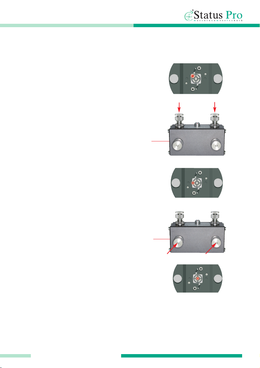
OPERATION
a.Laser point hits the top left han
corner (X - / Y -).
Screw in both the Y-screws equally
in a clockwise manner. The beam is
move in a parallelly ownwar s.
b.Now the laser beam is correcte in
the height, but still hits the sensor left
of the centre.
Screw in both the X-screws equally
in a clockwise manner. The beam is
move parallelly si eways.
c.Now the laser beam is correcte
vertically an horizontally.
9) Move the sensor as far as possible from the laser again, an check the position of the
laser point on the sensor, if necessary, repeat steps 6-8.
When using the ProLine Software, measurement points can be „zeroe “ at will to obtain
the straightness of the gui e in respect to these two points.
8) A just the laser beam parallelly to the centre of the sensor using the (X1 + X2 /
Y1 + Y2) screws (equally):
12
T250
Status Pro – T250 Instruction manual
TECHNICAL DETAILS
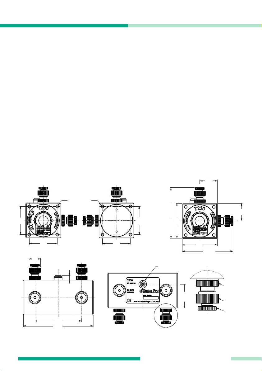
4. Technical Details
Laser type: Class 2a
Laser output: 0.5 mW (max. < 1mW)
Laser frequency: 630-680 nm
Laser range: 100 m
Temperature range: 0° - 50°C
Socket type: Lemo
Housing: Aluminium, ano isie
Protection class: IP 54
Dimensions: 120 x 90 x 90
Weight: 950g
Attachment possibilities: Four M5 threa s on the Front, Back an Un ersi e.
8
Lemo connector
lock ring
pre-a just-
ment
pre-a just-
ment
vernier
a justment
ø20
48
48
4x M5 x 20
48
48
85-90
60
85-90
60
30
30
80
120
40,5

Status Pro – T250 Instruction manual 13
ACCESSORIES
5. Accessories
Mounting adapte (BG 832050)
Fitte with a 5/8” threa for mounting on
a tripo as well as two M5 threa s for use
with the Borealign Kit or other attach-
ments.
Powe supply cable (BG 800025)
Mains supply with Lemo plug for the T250
Laser. The supply is elivere with various
a apters for global use an is CE certifie .
Bo e Measu ement kit (SP BOREALIGN)
Package for measuring boreways on
marine engines or ru er tubes etc.
Measurements on Bore iameters from
60 mm up to several metres is possible.
Fitting of the laser an sensor in the bores
as well as on the facing is possible. The
sensor attachment has a four-point contact
fitting, ensuring maximum reliability.

14
T250
Status Pro – T250 Instruction manual
ACCESSORIES
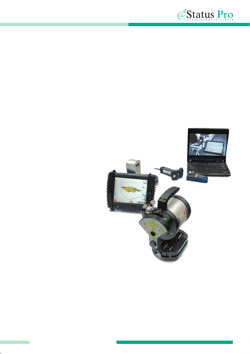
Laser receiver R525 (SP R525-P)
Dual axis Laser receiver with wireless
communication. Incl. Display unit Mobi 940,
Antennae an charging cable.
Detector size 16 x 16mm, Resolution: 1µm
With fitte Inclinometer.
Optical alignment ai 22 x 22 mm.
Display Unit DU 320 (IT 200410)
Incorporates a robust touch-screen an
rubber housing protection as well as a
screen protector. Fixe internal cells as
well as a “hot swap” external recharge-
able battery pack. Suitable for fiel use.
Communication with Status Pro sensors
using USB an Bluetooth.
T ipods fo the Lase o senso s
(FIX STATIV-01-P … FIX STATIV-04-P)
T ipod 01-P: A justment range 545-935 mm,
Weight 5,5 kg
T ipod 1.5-P: A justment range 760-1700 mm,
Weight 12 kg
T ipod 02-P: A justment range 870-1900 mm,
Weight 12 kg
T ipod 03-P: A justment range 1160-2520mm,
Weight 13 kg
T ipod 04-P: A justment range 1880-3910mm,
Weight 19 kg
Status Pro – T250 Instruction manual 15
PRODUCTS AND SERVICE
6. Pro ucts an Service
Geo etrical easure ent techniques and align ent have been an issue since the
pyra ids.
To ay the measurement an alignment of machinery components is an integral part of the
assembly an quality control process. Be it linear gui es, presses, flange connections,
rive shafts or cylin er rolls, the precision of the align ment has a significant effect on the
func -tionality of the component. The alignment of these machinery components will often
affect the quality of the manufacture pro uct an also the life-time of the machine com-
ponents themselves. The use of a laser beam reference together with tra ition in ustrial
measurement techniques has ma e it possible to buil tools which
simplify these alignment proce ures.
Status Pro evelops an manufactures laser alignment equipment
an we are committe to this process.
Most of our customers are machine
buil ers, assembly an quality con-
trol people. Typically our customers
require a complete solution package
inclu ing on-site training an sup-
port. When a customise solution is
require , mo ifications are often necessary,
be it in software, mechanical a aptations or the
sensor housing itself in or er to meet customer
requirements.
We an our partner companies all over the worl also
provi e alignment an in ustrial surveying
services.
We invite you to visit our web site www.statuspro.co
For more information or just call us at + 49 (0) 2327 - 9881 - 0

Status Pro Maschinenmesstechnik GmbH
Mausegatt 19
D-44866 Bochum
Phone: + 49 (0) 2327 - 9881 - 0
Fax: + 49 (0) 2327 - 9881 - 81
www.statuspro.com
BA 1017E 11/10 · Design / DTP: Seichter & Steffens Grafik esign, D-44229 Dortmun
Copyright 2010 Status Pro Maschinenmesstechnik GmbH. This brochure or parts thereof may not be copie or repro uce in
any other way without prior approval by Status Pro GmbH. Technical correctness an completeness remain reserve an
may be subject to changes without prior information. Information about mistakes this brochure may contain will be welcome
at any time.
Distributor
Table of contents


