NOTES ABOUT THE PLACING
When selecting the place of NB.Z2000 operation, we have in mind the general
limitation about the environmental conditions as they describe to the
specifications and precautions.
Choose the place of the installation, so that all the connections of NB.Z2000 can
be accessible at any time.
Choose a socket that is able to withstand the requirement of the power. Connect
the NB.Z2000 with a suitable system at the ground –is very important for the
high operation of any AM transmitter, especially when you use a high voltage
external amplifier. In the past the grounding in a copper water pipe is used for
this purpose very often. The recent reviews to the National Electric Code have
shown that this practice is a violation of the code. We must be reminded of the
fact that the modern water supply and facilities use plastic pipe that can’t be use
as grounding.
Never use in connection a gas or an electrical conductor. It may cause explosion
or electrocution. A good grounding system not only prevents electrocution, but it
helps to ensure seamless operation and reduces interference to the TV and to
TVI/BCI.
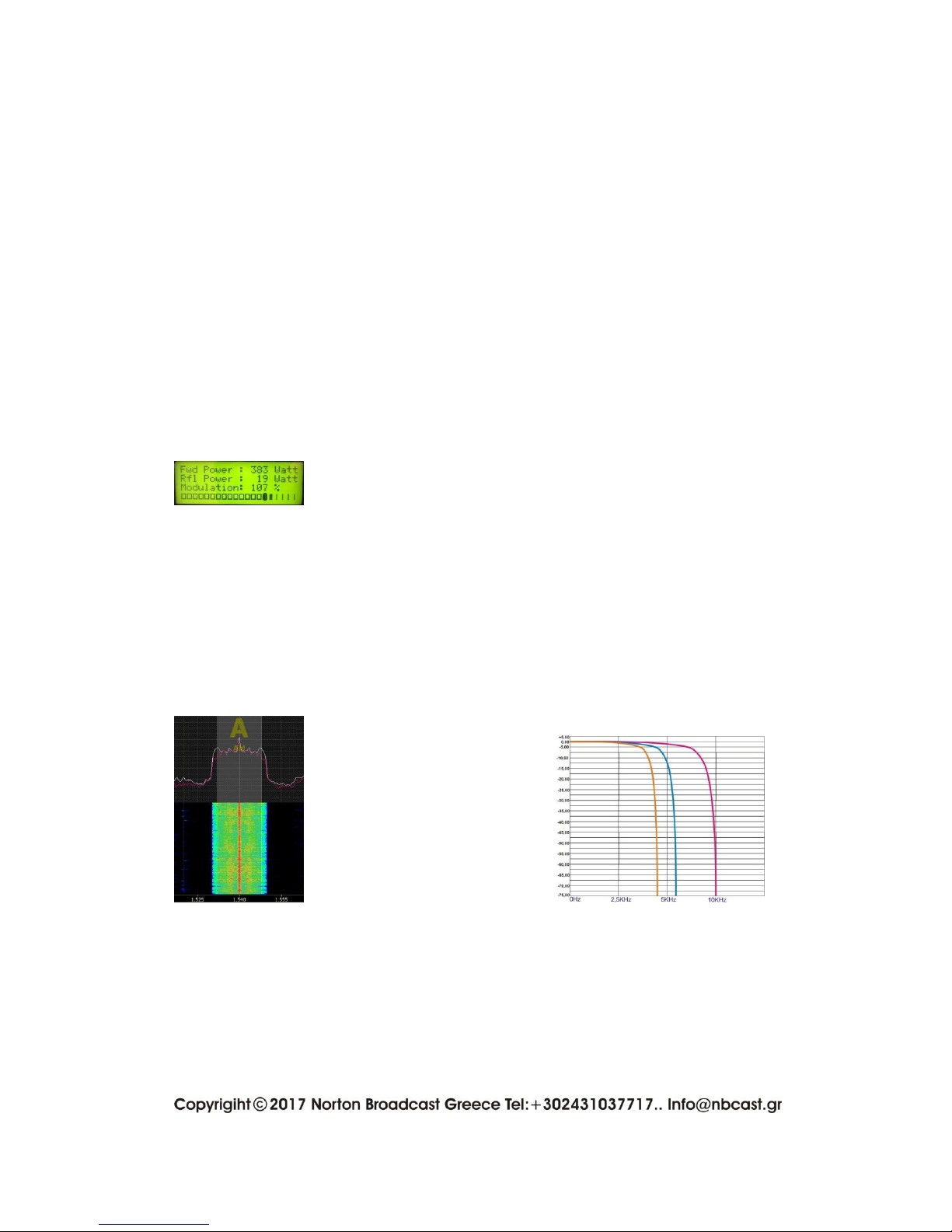
ANTENNA TUNER
The standing wave ratio (SWR) can be increased significantly when we use an
antenna outside the frequencies range, for which it is coordinated. The final
power of the amplifier will operate to its maximum performance only when its
dummy load is resistor, viz the swr are nearly to the 10 reflections.
The right ohmic resistance in cooperation with the properly at wavelength
constructed antenna, but also the adequate grounding, will allow the NB.Z2000 to
attach correctly with maximum power and without energizing any of the
protections.
Attention: all the above also applies for any amplifier that may potentially be set
in operation after the NB.Z2000 and to strengthen the signal. The wrong ohmic
input resistance of the amplifier will set in danger the NB.Z2000 and probably will
change its characteristics.
In case that you have any of the two above problems, it would be good to ask
help from an expert.