STATUS SCIENTIFIC CONTROLS FGD10A-M User manual

STATUS SCIENTIFIC CONTROLS
Issue:
10
Date:
21/1/19
Firmware:
V2.1.0
Installation, Commissioning &
Routine Gas Testing Manual
Gas Detector
Type FGD10A-M

STATUS SCIENTIFIC CONTROLS
Installation, Commissioning & Routine Gas Testing
FGD10A-M Gas Detector

STATUS SCIENTIFIC CONTROLS
Installation, Commissioning & Routine Gas Testing
FGD10A-M Gas Detector
Declaration of Conformity
We declare that, on the date the equipment accompanied by this declaration is placed on the market, the equipment conforms with all
technical and regulatory requirements of the directives listed below.
Description of Equipment:
The FGD10A-M Series of Fixed Gas Detectors for thedetection of Oxygen, Toxic or Flammable gases.
ATEX Flameproof Certified for use in Group IIC hazardous locations.
Directive 2014/34/EU ATEX
The following harmonised standards were used in support of this declaration:
EN 60079-0:2012+A11:2013 Explosive atmospheres Part 0: Equipment –General requirements
The FGD10 was originally certified to standard EN 60079-0:2006. This standard has been compared with theabove harmonised standard
and no significant changes have occurred that are applicable this equipment.
EN 60079-1:2014 Explosive atmospheres Part 1: Equipment protection by flameproof enclosures ‘d’.
The FGD10 was originally certified to standard EN 60079-1:2007 but is considered compliant with the above harmonised standard
because both the instrument housing and GSH4 sensor housing are certified to that standard.
Notified Body for Hazardous Area Certification:
SIRA Certification Service
Rake Lane, Eccleston,
Chester, CH4 9JN.
Notified Body Number: 0518
Notified Body for ATEX Quality Assurance Notification:
Baseefa
Rockhead Business Park
Staden Lane, Buxton SK17 9RZ, UK
Notified Body Number: 1180
Hazardous Area Certificate Number:
SIRA 08ATEX1031X II 2 G Ex d IIC
T4 (Ta = -20OC + 60OC )
T5 (Ta = -20OC + 50OC ) * T5 & T6 ratings are not valid for
T6 (Ta = -20OC + 35OC ) versions fitted with an externally
mounted sensor.
ATEX Quality Assurance Notification Number:
2056
Place of Manufacture:
Mansfield, Nottinghamshire, UK. Date mark applied –see product
ISO 9001:2015 Quality Management System:
Certificate No. GB93/1938
2014/30/EU –Electromagnetic Compatibility
Harmonised Standards:
EN50270:2006 Electromagnetic compatibility - Electrical apparatus for the detection and measurement of combustible gases, toxic gases
or oxygen.
Authorised Signatory to this declaration, on behalf of the manufacturer:
Name: David Stuttard Title: Managing Director
Address: Status Scientific Controls Ltd, Hermitage Lane Industrial Estate, Kings Mill Way
Mansfield, Nottinghamshire, NG18 5ER, United Kingdom
Signature Date: 21/1/19

STATUS SCIENTIFIC CONTROLS
Installation, Commissioning & Routine Gas Testing
FGD10A-M Gas Detector

STATUS SCIENTIFIC CONTROLS
Installation, Commissioning & Routine Gas Testing
FGD10A-M Gas Detector
TD18/032
Issue:
10
Change Note:
1869
Page 4
CONTENTS
1. FIRMWARE REVISION...................................................................................6
2. PACKAGE CONTENTS ..................................................................................7
3. SCOPE OF THE MANUAL..............................................................................7
4. DESCRIPTION................................................................................................8
4.1. RELAYS ................................................................................................10
5. INSTALLATION ............................................................................................ 11
5.1. CABLE ENTRIES.....................................................................................12
5.2. MOUNTING AND TERMINAL ACCESS .........................................................12
5.3. FGD10A-M CONNECTIONS ....................................................................14
5.4. POWER SUPPLY ....................................................................................15
5.5. ANALOGUE OUTPUT............................................................................... 15
5.6. RS485 OUTPUT ....................................................................................15
6. COMMISSIONING.........................................................................................16
6.1. APPLYING POWER..................................................................................16
6.2. SCREEN SAVER.....................................................................................17
6.3. INDICATORS ..........................................................................................18
7. RELATIVE RESPONSE CHARACTERISTICS..............................................18
8. INITIAL GAS TESTING.................................................................................20
8.1. ZERO GAS.............................................................................................20
8.2. TEST GAS .............................................................................................22
8.2.1. Gas connection points.....................................................................................22
8.2.2. Sampling time..................................................................................................23
8.2.3. Suggested calibration gas levels. ...................................................................23
9. SOFTWARE FEATURES.............................................................................. 24
9.1. MENU SELECTION..................................................................................26
9.1.1. Password Enabled Menu ................................................................................26
9.1.2. Sensor Zero.....................................................................................................28
9.1.3. Sensor Span....................................................................................................29
9.1.4. Sensor FSD.....................................................................................................32
9.1.5. 4 –20 mA Current Loop..................................................................................33
9.1.6. Alarm Levels....................................................................................................34
9.1.7. Firmware Version............................................................................................35
9.1.8. Relays..............................................................................................................36
9.1.9. Latching Relays...............................................................................................37
9.1.10. Password Enable ............................................................................................38
9.1.11. Set Password ..................................................................................................39
9.1.12. Diagnostics......................................................................................................41
9.1.13. Hysteresis........................................................................................................48
9.1.14. Display Resolution...........................................................................................49
9.1.15. Restore............................................................................................................50

STATUS SCIENTIFIC CONTROLS
Installation, Commissioning & Routine Gas Testing
FGD10A-M Gas Detector
TD18/032
Issue:
10
Change Note:
1869
Page 5
9.1.16. Warm-up timer.................................................................................................51
9.1.17. Zero Suppression............................................................................................52
9.1.18. Sensor Type....................................................................................................53
9.1.19. Sensor Bias (Toxic sensor only) .....................................................................56
9.1.20. Gain Setting (Toxic Sensor only) ....................................................................56
9.1.21. Sensor Units....................................................................................................57
9.1.22. Time.................................................................................................................58
9.1.23. Screen Saver...................................................................................................59
9.1.24. Set Flammable Gas Type ...............................................................................60
9.1.25. Set Flammable Gas LEL. (Infrared sensor only) ............................................61
9.1.26. Set Flammable Gas Correction Factor ...........................................................62
9.1.27. Set Flammable Gas Default LEL and Correction Factor ................................63
10. MODBUS INTERFACE..................................................................................64
MODBUS (ISO/IEC 7498-1 PHYSICAL LAYER)DESCRIPTION.....................................64
10.1. MODBUS (ISO/IEC 7498-1 APPLICATION LAYER)DESCRIPTION.................64
10.2. MODBUS REGISTER LIST........................................................................65
10.3. MODBUS PROGRAMMING EXAMPLES: ......................................................74
10.3.1. Example 1: Read Gas Level command. ........................................................74
10.3.2. Example 2: Method for recalculating CRC checksum: ..................................76
10.3.3. Example 3: Received Modbus frame from FGD10AM ...................................77
10.3.4. Example 4: Write Calibration gas level to Modbus register 40126.................77
10.4. BROADCAST MESSAGES. .......................................................................78
10.5. WIRING:................................................................................................78
10.6. MODBUS REFERENCES:..........................................................................78
11. ROUTINE GAS TESTING.............................................................................. 79
12. SENSOR REPLACEMENT............................................................................ 80
12.1. INFRARED SENSOR ................................................................................80
12.2. OXYGEN /TOXIC SENSOR.......................................................................86
12.3. FLAMMABLE (PELLISTOR)SENSOR ..........................................................94
13. FUSES ........................................................................................................103
14. SPECIFICATION......................................................................................... 104
15. DIMENSIONS.............................................................................................. 105
15.1. OXYGEN /TOXIC /PELLISTOR VERSIONS ...............................................105
15.2. INFRARED VERSIONS............................................................................106
16. CERTIFICATION......................................................................................... 107

STATUS SCIENTIFIC CONTROLS
Installation, Commissioning & Routine Gas Testing
FGD10A-M Gas Detector
TD18/032
Issue:
10
Change Note:
1869
Page 6
1. FIRMWARE REVISION
V2.1.0 29/04/14 New features and bug fixes. Bug fix for Hydrogen (Toxic) in
Gain Set Menu. SSCL (only) factory setup menu. RTC
calibration in TIME menu. Extra diagnostic menu and
diagnostic functions
V2.0.4 29/01/14 Fix for diagnostics –Oxygen-display span data.
V2.0.3 22/12/13 Pellistor support added. Enhanced menu system. Modbus
support added.
V2.0.2 08/11/13 Enhanced context sensitive menus. Modbus NOT
supported in this release
V2.0.1 06/09/13 Release for Exhibition. Flammable gases list
V2.0.0 28/06/13 Initial release –Modbus version

STATUS SCIENTIFIC CONTROLS
Installation, Commissioning & Routine Gas Testing
FGD10A-M Gas Detector
TD18/032
Issue:
10
Change Note:
1869
Page 7
2. PACKAGE CONTENTS
The FGD10A-M is supplied in a box containing the following items:-
Description
FGD10A-M Gas Detector
Magnetic pen
Installation manual
Calibration certificate
Optional:-
Weather guard
3. SCOPE OF THE MANUAL
This manual relates to versions of the FGD10A-M gas detector with one of
the following sensor types:-
•An Infrared sensor for the detection of Hydrocarbon (HC) or CO2 gases
•A Pellistor sensor for the detection of hydrocarbon and hydrogen gases
•A Toxic sensor
•An Oxygen sensor
Note –Infrared sensors are unsuitable for the detection of Hydrogen.
However, this gas can be detected using a version of the FGD10A-M
fitted either with pellistors or suitable electro-chemical sensors.

STATUS SCIENTIFIC CONTROLS
Installation, Commissioning & Routine Gas Testing
FGD10A-M Gas Detector
TD18/032
Issue:
10
Change Note:
1869
Page 8
4. DESCRIPTION
FGD10A-M GAS DETECTOR
FGD10A-M GAS DETECTOR FITTED WITH
PROTECTIVE WEATHERGUARD

STATUS SCIENTIFIC CONTROLS
Installation, Commissioning & Routine Gas Testing
FGD10A-M Gas Detector
TD18/032
Issue:
10
Change Note:
1869
Page 9
The FGD10A-M is an explosion protected ATEX and IECEx certified fixed
gas detector for use in potentially explosive atmospheres. The unit may be
optionally fitted with a protective weather guard as shown in the photograph.
IMPORTANT –When used in hostile environments (e.g. oil platforms
where the instrument is exposed to salt spray or diesel) it is
recommended that the FGD10A-M is always fitted with its protective
weather guard. The weather guard is attached with tamperproof screws
to ensure that it is not inadvertently removed.
The unit comprises an instrument housing having two cable gland entries
and containing the connection terminals, electronics and display window.
The housing containing the gas sensor has an M27 thread and is screwed
into the bottom of the unit. The sensor housing itself is a certified component
and must not be removed in service.
Behind the display window are:-
•A 160x128 graphics OLED display
•Four magnetically operated switches that are activated through the
display window using a magnetic pen that is supplied with the unit.
•LED indicators for POWER
The magnetically operated switches allow the unit to be calibrated
whilst power is still applied without the need to remove the cover from
the unit.
The main electrical features of the unit are:-
•Power supply –8 to 24 volts dc (non-intrinsically safe)
•Analogue output –4 to 20mA dc
•RS485 communications output.
•Relay contact outputs for Alarm 1, Alarm 2 and Fault.
•Gland entry threads available –20mm, ½” or ¾” NPT

STATUS SCIENTIFIC CONTROLS
Installation, Commissioning & Routine Gas Testing
FGD10A-M Gas Detector
TD18/032
Issue:
10
Change Note:
1869
Page 10
4.1. Relays
The FGD10A-M relay version has 3 factory-fitted relays. Each provides a set
of voltage free changeover contacts to perform the following control
functions:-
•Alarm Level 1
•Alarm Level 2
•Fault
Versions without relays fitted are also available.
The self-adhesive label on the outer surface of the enclosure indicates
whether or not the relays are fitted as shown below:-
GAS DETECTOR TYPE FGD10
CONTROL RELAYS FITTED
GAS DETECTOR TYPE FGD10
NO CONTROL RELAYS FITTED

STATUS SCIENTIFIC CONTROLS
Installation, Commissioning & Routine Gas Testing
FGD10A-M Gas Detector
TD18/032
Issue:
10
Change Note:
1869
Page 11
5. INSTALLATION
It is important that the correct cable and gland types are used when installing
the FGD10A-M in a hazardous location.
The cable entry devices and blanking elements of unused apertures shall be
of a certified flameproof type, suitable for the conditions of use and correctly
installed.
With the use of conduit, a suitable certified sealing device such as a stopping
box with compound shall be provided immediately at the entrance to the
flameproof enclosure.
In order to prevent dangerous overloading of the FGD10A-M gas detector, it
is important that the installer observes the relay contact rating and ensures
that external circuits connected to the relay contacts are suitably protected
from exceeding that rating and associated cabling is adequately rated and
suitably installed.
Guidance on the correct installation of systems is provided by EN60079-14:
2008. It is the responsibility of the installer to ensure compliance with the
relevant standards.
To ensure effective gas detection, the FGD10A-M must be located at a
height appropriate to the density of the target gas relative to air. For
example, Methane (relative density 0.55) is lighter than air and so it will tend
to accumulate at a high level within a confined space. Whereas Petroleum
(relative density 2.8) is heavier than air and it will tend to accumulate at
around ground level.
European standard EN 60079-20-1:2010 provides comprehensive
flammability data (including relative density) on approximately 300 types of
gases.

STATUS SCIENTIFIC CONTROLS
Installation, Commissioning & Routine Gas Testing
FGD10A-M Gas Detector
TD18/032
Issue:
10
Change Note:
1869
Page 12
5.1. Cable entries
The cable entry threads are 20mm, ½” or ¾” NPT female.
The FGD10A-M enclosure is manufactured from die cast aluminium.
Therefore, the use of glands, conduit fittings and blanks made from brass
should be avoided because if moisture is present, bi-metallic corrosion may
occur due to the chemical reaction between the two materials.
Glands and fittings plated with nickel, tin or zinc will provide improved
protection but in harsh environments the use of stainless steel is
recommended.
When connecting the cores inside the unit it is beneficial to use pointed-nose
pliers to carefully guide the cable cores from the cable entries at the rear of
the enclosure towards the PCB mounted terminal connections situated near
to the front of the enclosure.
5.2. Mounting and terminal access
The FGD10A-M should be mounted and secured using the mounting holes
on the main unit.
Figures 2 and 3 shows details of the FGD10A-M terminal connections –
these can be accessed as follows:-.
1. Switch OFF the supply to the FGD10A-M.
2. Release the grub screw located near the lip of the enclosure
cover.
Note: It is not necessary to completely remove the grub screw
to release the enclosure front cover.
3. Remove the enclosure front cover by rotating it several times in
an anti-clockwise direction.
4. Unplug the top display board from within the enclosure by
pulling it forwards. The board is captivated by means of a nylon
wire in order to prevent it falling from the unit –take care to
ensure that the board is not damaged during installation. See
Figure 1.
5. The terminals can now be accessed.
Store the front cover such that it cannot be damaged or the thread
contaminated with dirt.

STATUS SCIENTIFIC CONTROLS
Installation, Commissioning & Routine Gas Testing
FGD10A-M Gas Detector
TD18/032
Issue:
10
Change Note:
1869
Page 13
Figure 1 –Unplugging the display board for
connection purposes

STATUS SCIENTIFIC CONTROLS
Installation, Commissioning & Routine Gas Testing
FGD10A-M Gas Detector
TD18/032
Issue:
10
Change Note:
1869
Page 14
5.3. FGD10A-M connections
Figure 2 –Armoured Cable Gland Installation
Figure 3 –EEx d Conduit Installation
Important
Connect
enclosure
earth-point
to a high
integrity
earth
ATEX certified Ex d armoured
cable glands
-+
PSU
-+
Aout
RS485
Armoured cable
Armoured cable
Mount vertically
as shown
N/O
COM
N/C
Relay 1
Alarm 1
N/O
COM
N/C
Relay 2
Alarm 2
N/O
COM
N/C
Relay 3
Fault
Important
Connect
enclosure
earth-point
to a high
integrity
earth
ATEX Certified compound-filled
conduit seals (stopping boxes)
-+
PSU
-+
Aout
RS485
Conduit
Conduit
Mount vertically
as shown
N/O
COM
N/C
Relay 1
Alarm 1
N/O
COM
N/C
Relay 2
Alarm 2
N/O
COM
N/C
Relay 3
Fault

STATUS SCIENTIFIC CONTROLS
Installation, Commissioning & Routine Gas Testing
FGD10A-M Gas Detector
TD18/032
Issue:
10
Change Note:
1869
Page 15
5.4. Power Supply
The FGD10A-M is powered from a 8 –24 volt dc, 5 W maximum output
supply. This may be either:-
a) An independent supply powering one or more units.
b) A supply that is an integral part of a control card within a monitoring
panel.
5.5. Analogue Output
The analogue output provides a means of indicating to external equipment
(e.g. data loggers, remote displays, control cards) the gas levels currently
being detected by the system. The output is in the form of the industry
standard 4 to 20mA current source.
The analogue output is factory set such that 4mA represents zero gas and
20mA represents the full scale gas level of the FGD10A-M.
Figure 4 –Analogue Output
5.6. RS485 Output
This output is designed to be compatible with a suitable controller fitted with
an RS485 serial communications port.
Note - The amplifier and
power supply may be
contained on the same
control card.
FGD10
0V
A+
0V
12-24V DC
Control
Unit
I (4-20mA)
PSU

STATUS SCIENTIFIC CONTROLS
Installation, Commissioning & Routine Gas Testing
FGD10A-M Gas Detector
TD18/032
Issue:
10
Change Note:
1869
Page 16
6. COMMISSIONING
Following completion of the installation:-
a) Replace the top display board using the locating pins on the
underside of the board to ensure that it makes connection with the
remainder of the electronics - see Figure 1.
b) Ensure that the front cover has not been contaminated with dirt -
paying particular attention to the thread. Replace the cover by
rotating it several times clockwise until it reaches its limit then
secure using the grub screw –do not over tighten.
6.1. Applying power
Once the installation is complete and the covers are secure then power can
be applied. The power source should be between 8 and 24 volts dc.
When power is first applied to the FGD10A-M, an initialisation procedure is
performed as follows:
L OGO
FGD10A
V1.1.1
Tel: (0)1234 123456
www.company.com
The FGD10A-M now displays the time remaining before the unit is fully
functional, usually 45 seconds, in the form of a progress bar. After the warm-
up time the detected gas level present is displayed and the FGD10A-M
becomes operational.
The normal screen is shown below:
0
Methane
22/05/2013 15:33:26
%LEL

STATUS SCIENTIFIC CONTROLS
Installation, Commissioning & Routine Gas Testing
FGD10A-M Gas Detector
TD18/032
Issue:
10
Change Note:
1869
Page 17
6.2. Screen Saver
The OLED display can shown signs of display retention when areas of the screen are
constantly illuminated. These effects reveal them selves when the background is a
colour other than black.
The screen defaults to a screen saver mode where the display alternates between the
display logo and the actual gas readings, as seen below:
L OGO
0
The logo and the gas readings alternate and appear at random positions on the
screen.
The screen normally will display the normal screen for 1 minute then will show the
screen saver for between 1 and 10 minutes.
The screen saver mode can be set up using the menu options as described later
The screen saver is deactivated for the following conditions
1) During alarm conditions
2) During a fault condition
3) On a key press, resets the normal display to 1 minute
4) During the menu options

STATUS SCIENTIFIC CONTROLS
Installation, Commissioning & Routine Gas Testing
FGD10A-M Gas Detector
TD18/032
Issue:
10
Change Note:
1869
Page 18
6.3. Indicators
Green Led for power.
Display colour changes to red for alarms and Yellow for faults.
Colour
Identity
Operation
Red
Display
Alarm
Display flashes a coloured box when an alarm level has
been reached.
Green
LED
Power
Always ON when power is connected.
Yellow
Display
Fault
Display flashes a coloured box when a fault is a detected.
7. RELATIVE RESPONSE CHARACTERISTICS
Unless otherwise specified, the FGD10A-M infrared hydrocarbon gas
detector is calibrated to provide an output signal linearised for methane (CH4)
during manufacture.
However, the gas detector will also respond to a range of hydrocarbon
gases. The characteristics shown in Figure 5 demonstrate the relative
response to some of the common hydrocarbons.
If the expected target gas is other than methane then either:-
a) The characteristics can be used as a guide when setting up the alarm
levels in the associated control unit, e.g. where a general hydrocarbon
response is required.
b) The FGD10A-M can be calibrated using a test gas for any of the gases
shown in Figure 5, using the span setting procedure as described in
Section 9.1.3.

STATUS SCIENTIFIC CONTROLS
Installation, Commissioning & Routine Gas Testing
FGD10A-M Gas Detector
TD18/032
Issue:
10
Change Note:
1869
Page 19
Table of contents
Other STATUS SCIENTIFIC CONTROLS Gas Detector manuals

STATUS SCIENTIFIC CONTROLS
STATUS SCIENTIFIC CONTROLS FGD10B Series Guide
STATUS SCIENTIFIC CONTROLS
STATUS SCIENTIFIC CONTROLS FGD2 User manual
STATUS SCIENTIFIC CONTROLS
STATUS SCIENTIFIC CONTROLS FGD4 User manual
STATUS SCIENTIFIC CONTROLS
STATUS SCIENTIFIC CONTROLS FGD 3 Series User manual
STATUS SCIENTIFIC CONTROLS
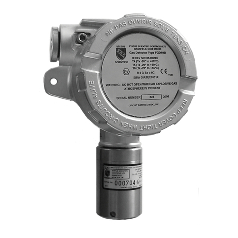
STATUS SCIENTIFIC CONTROLS FGD10B Series User manual
STATUS SCIENTIFIC CONTROLS
STATUS SCIENTIFIC CONTROLS FGD10A User manual
