Staubli POAG-KBT6-EC/4 User manual
1 / 4
4
1a
1b
1c
1d
1
2
3
MA564 (de_en)
Montageanleitung
MA564 (de_en)
Assembly instructions
POAG-KBT6-EC/4
POAG-KBT6-EC/6
POAG-KBT6-EC/4-6
POAG-KBT6-EC/4
POAG-KBT6-EC/6
POAG-KBT6-EC/4-6
Inhalt
Sicherheitshinweise ���������������������������������������������������������������������2
Vorbereitung der Leitung��������������������������������������������������������������3
Montage��������������������������������������������������������������������������������������4
Content
Safety Instructions �����������������������������������������������������������������������2
Lead preparation �������������������������������������������������������������������������3
Assembly�������������������������������������������������������������������������������������4
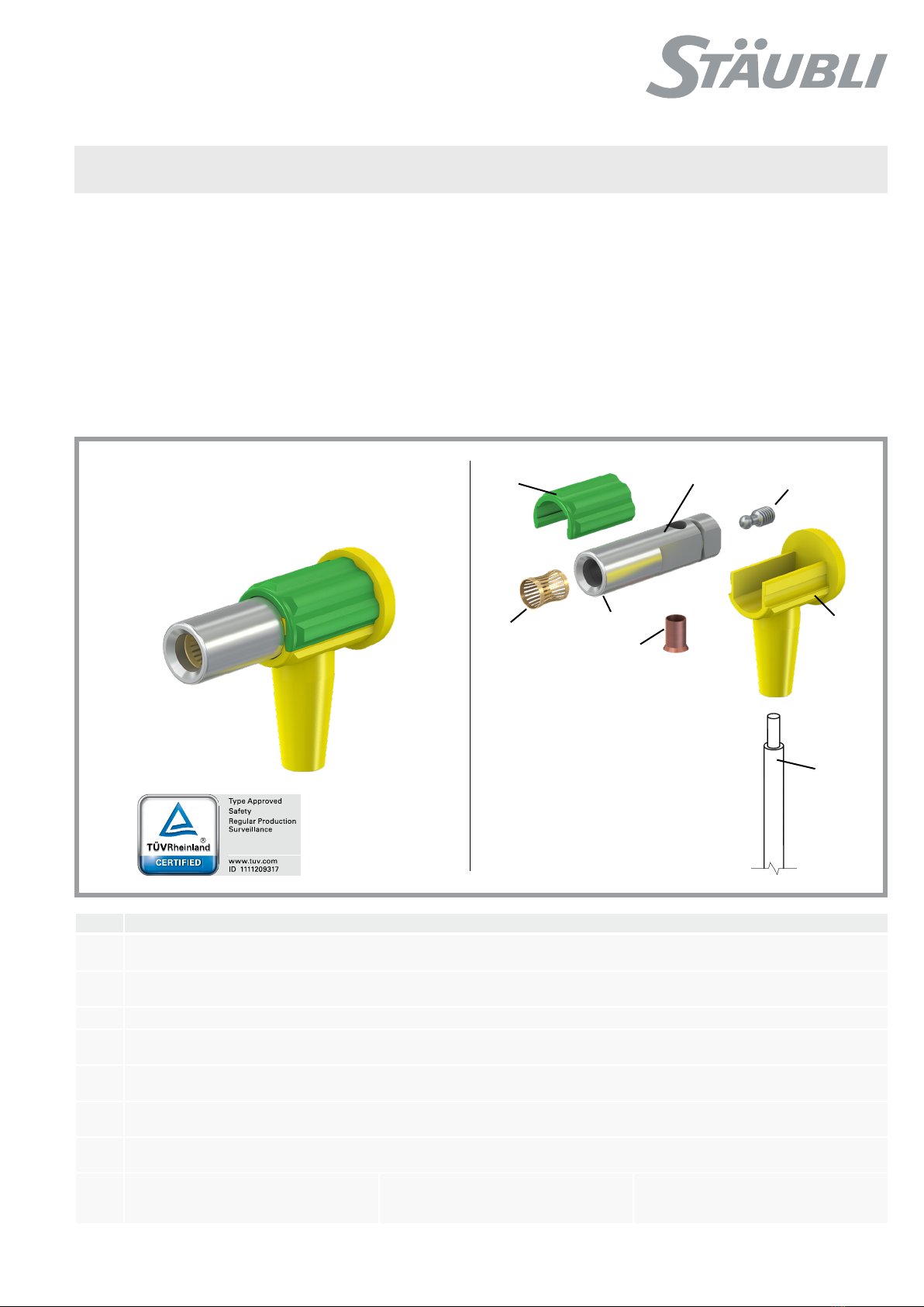
Pos. Bezeichnung / Description
1Buchse, werkseitig vormontiert
Socket, pre-assembled
1a Buchsenkörper
Socket body
1b MULTILAM
1c Madenschraube
Grubscrew
1d Aderendhülse
Lead end sleeve
2Isolierungs-Oberteil
Upper part of insulator
3Isolierungs-Unterteil
Lower part of insulator
4Leitung (nicht mitgeliefert)
Lead (not supplied)
Außen-Ø / Outer Ø
POAG-KBT6-EC/4: 4,8 mm
POAG-KBT6-EC/6: 6,0 mm
Leitungsquerschnitt / Lead cross section:
POAG-KBT6-EC/4: 4,0 mm²
POAG-KBT6-EC/6: 6,0 mm²
2 / 4
Sicherheitshinweise Safety instructions
Die Produkte erfüllen die angegebenen technischen Daten nur,
wenn die hier beschriebenen Schritte eingehalten und fach-
männisch ausgeführt werden� Die Montage und Installation der
Produkte darf ausschließlich durch Elektrofachkräfte oder elekt-
rotechnisch unterwiesene Personen unter Berücksichtigung aller
anwendbaren gesetzlichen Sicherheitsbestimmungen und Rege-
lungen erfolgen�
The products will only conform to the specified technical data if
the steps described here are correctly followed and carried out in
a professional manner� The products may be assembled and in-
stalled by electrically skilled or instructed persons duly observing
all applicable safety regulations�
Benutzen Sie nur die angegebenen Einzelteile und Werkzeuge�
Weichen Sie nicht von den hier beschriebenen Vorgängen zur
Vorbereitung und Montage ab, da sonst bei der Selbstkonfek-
tionierung weder die Sicherheit noch die Einhaltung der techni-
schen Daten gewährleistet ist� Ändern Sie das Produkt in keiner
Weise ab�
Use only the components and tools specified by Stäubli� In case
of self-assembly, do not deviate from the preparation and assem-
bly instructions as stated herein, otherwise Stäubli cannot give
any guarantee as to safety or conformity with the technical data�
Do not modify the product in any way�
Für Schäden infolge einer Nichtbeachtung dieser Montage- und
Sicherheitshinweise übernimmt Stäubli Electrical Connectors kei-
nerlei Haftung�
Stäubli Connectors assumes no liability for any damage resulting
from failure to follow these assembly and safety instructions�
Der Steckverbinder wurde für die Selbstmontage von Verbin-
dungsleitungen für den Potentialausgleich konzipiert und zerti-
fiziert�
This connector is designed and certified for self-assembly of con-
necting cables for equipotential bonding�
IEC 60417-6042
Vorsicht, Gefahr des elektrischen Schlags Caution, risk of electric shock
Die hier beschriebenen Arbeiten dürfen nicht an stromführenden
oder unter Spannung stehenden Teilen durchgeführt werden�
The operations described here must not be performed on live or
current-carrying parts�
Der Schutz vor einem elektrischen Schlag muss durch das End-
produkt (d� h� den korrekt konfigurierten Steckverbinder) gege-
ben sein und vom Anwender selbst sichergestellt werden�
Electric shock protection must be provided by the end product
(i�e� the correctly configured connector) and ensured by the user
themselves�
Die Steckverbindung darf nicht unter Last getrennt werden� Plug connections must not be disconnected while under load�
ISO 7000-0434B
Vorsicht Caution
Vor jedem Gebrauch ist visuell zu prüfen, ob keine äußeren Män-
gel vorhanden sind (besonders an der Isolation)�
Bei sichtbaren Beschädigungen der Baugruppe darf diese nicht
mehr verwendet werden�
Each time the connector is used, it should previously be
inspected for external defects (particularly the insulation)�
In case of any visible damage, the component must no longer
be used�
Nicht gesteckte Steckverbinder sind vor Feuchtigkeit und
Schmutz zu schützen� Die Steckverbinder dürfen nicht in ver-
schmutztem Zustand miteinander gesteckt werden�
Unmated connectors must be protected from moisture and dirt�
The male and female parts must not be plugged together when
soiled�
Nützlicher Hinweis oder Tipp Useful hint or tip
Weitere technische Daten entnehmen Sie bitte dem Produktka-
talog�
For further technical data please see the product catalog�
3 / 4
2
4
5
1
3
4
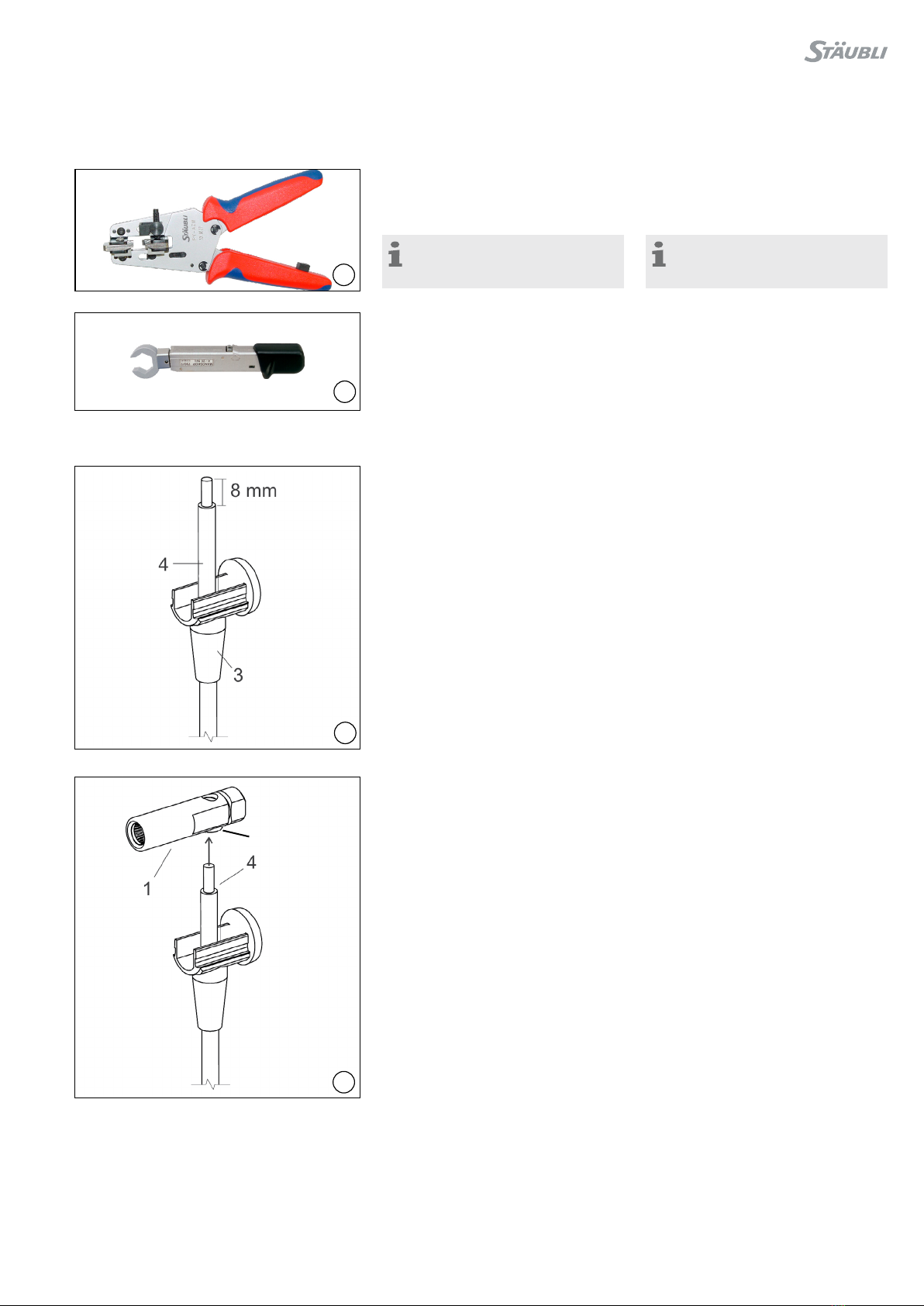
Erforderliches Werkzeug Tools required
(ill. 1)
Abisolierzange PV-AZM
Bestell-Nr� 32�6027
(ill. 1)
Stripping pliers PV-AZM
Order No� 32�6027
Hinweis:
Bedienungsanleitung MA267,
www�staubli�com/electrical
Note:
Operating instructions MA267,
www�staubli�com/electrical
(ill. 2)
Drehmomentschlüssel SW8
(ill. 2)
Torque wrench 8 mm
Vorbereiten der Leitung Lead preparation
(ill. 3)
Leitung 4durch Isolierungs-Unterteil 3
fädeln und abisolieren (ca� 8 mm)�
(ill. 3)
Thread lead 4through lower part of
insulator 3and strip (approx� 8 mm)�
(ill. 4)
Aderendhülse 1d in die Buchse 1ste-
cken und anschließend die Leitung 4�
(ill. 4)
Put lead end sleeve 1d into the socket 1
and insert the lead 4�
1d
4 / 4
56
7
Hersteller/Producer:
Stäubli Electrical Connectors AG
Stockbrunnenrain 8
4123 Allschwil/Switzerland
Tel. +41 61 306 55 55
Fax +41 61 306 55 56
www.staubli.com/electrical
© by Stäubli Electrical Connectors AG, Switzerland – MA564 – 01.2021, Index b, Marketing Communications – Änderungen vorbehalten / Subject to alterations
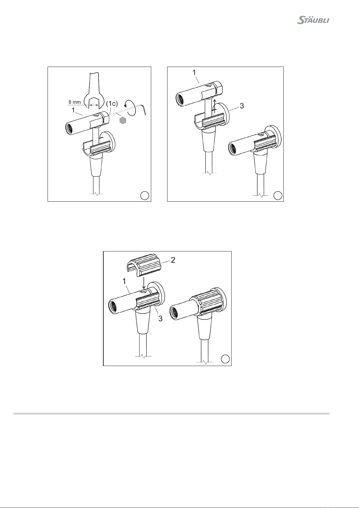
Montage Assembly
(ill. 5)
Madenschraube 1c festziehen, Schraube muss vollständig in
Buchse 1verschwinden�
Anzugsdrehmoment 0,7 N m ��� 1,0 N m („handfest“)�
(ill. 5)
Tighten grubscrew 1c, screw must completely disappear into
socket 1�
Tightening torque 0�7 N m ��� 1�0 N m (“hand-tight”)�
(ill. 6)
Isolierungs-Unterteil 3heranschieben, so dass Buchse 1darin
liegt�
(ill. 6)
Push up lower part of insulator 3so that socket 1rests in it�
(ill. 7)
Isolierungs-Oberteil 2aufsetzen, so dass sich dessen “Grat” in
die Nut der Buchse 1einpasst� Danach Isolierungs-Ober- und
-Unterteil 2und 3zusammendrücken, bis beide spürbar ineinan-
der rasten�
(ill. 7)
Place upper part of insulator 2in position so that its “ridge” fits in
the slot of the socket 1�
Then press the upper and lower parts of insulator 2and 3togeth-
er until they are felt to engage in each other�
This manual suits for next models
2
Other Staubli Accessories manuals


