FIBER FOX MINI3S User manual

Rev.0.01
This User Manual explains the use, performance characteristics, and cautions about MINI3S fusion splicer
and how to install and operate it. The primary goal of this manual is to make the user as familiar with the
splicer as possible.

01
Preface
Thank you for choosing MIN3S Arc Fusion Splicer. This product delivers ultra fast
splicing time and has an incredibly short shrinking time. It uses the prole alignment
technique and extremely accurate alignment process to ensure precise splice
loss estimation. A new shrinking technology makes that the shrink time is greatly
reduced, thus resulting in an extremely fast total cycle time. The splicer is designed
to withstand harsh environmental conditions. Its lightweight, yet robust, compact and
ergonomic design allows users to easily carry or move. MINI3S has a menu-driven
user interface with dynamic function buttons and a fully automatic splice process.
For more information of MINI3S, please contact local agent or visit our ocial
website.
Important!
We recommend all users to read this manual before operating MINI3S fusion splicer.

0302
3.6 Preparing the Fiber 15
3.7 How to Splice 16
3.8 Inspecting the Fiber 17
3.9 Splicing 18
3.10 How to Protect Splice 19
Chapter 4 Splice Mode
4.1 Displaying the Active Splice Program 20
4.2 Selecting a Splice Program 20
4.3 General Splicing Steps 21
4.4 Parameters for Normal Splicing Process 23
Chapter 5 Splice Option 25
Chapter6 Heater Mode
6.1 Heater Template 26
6.2 Select Heat Mode 26
6.3 Edit Heat Mode 27
6.4 Deleting Heat Mode 27
6.5 Heat Mode Parameters 28
Chapter 7 Maintenance Menu
7.1 Replace Electrodes 29
7.2 Stabilize Electrodes 30
7.3 Diagnostic Test 30
7.4 Dust Check 31
7.5 Motor Calibration 31
7.6 Arc Calibration 32
7.7 Electrode Setting 32
7.8 Quick Optimize 33
7.9 Motor Drive 34
Contents Contents
Chapter1 Technical Parameters
1.1 Applicable Fiber Type 05
1.2 Splice Loss 05
1.3 Splice Mode 05
1.4 Heater 05
1.5 Power Supply 06
1.6 Size and Weight 06
1.7 Environmental Conditions 06
1.8 Others 06
Chapter 2 Installation
2.1 Safety Warning and Precautions 07
2.2 Operational Safety Warnings 07
2.3 Maintenance and External Care Precautions 08
2.4 Transport and Storage Precautions 08
2.5 Installation 09
2.6 Splice Overview 09
2.7 Power Supply Method 10
2.8 Charging Process 11
2.9 Charging Methods 11
2.10 Battery Status 11
2.11 Battery Refresh Cycle 12
2.12 Heater 12
Chapter 3 Basic Operation
3.1 Power Connection 13
3.2 Battery Check 13
3.3 Turn On the Splicer 14
3.4 Adjust Monitor Position 14
3.5 Adjust LCD Backlight Brightness 14

0504
Chapter 1 Technical Parameters
1.1 Applicable Fiber Type
1.2 Splice Loss
1.3 Splice Mode
SM(ITU-TG.652&G.657)/MM(ITU-TG.651)/DS(ITU-TG.653)/NZDS(ITU-TG.655)
/ITU-TG.657A/ITU-TG.657B
Fiber count: Single
Applicable ber / cable diameter: 0.25mm/0.9mm/2.0mm/2.4mm/3.0mm/ Indoor
Cable
Applicable ber diameter: Cladding diameter: 150μm / Coating diameter:100μm ~
3000μm
Same ber is spliced, measured by insertion method relevant to ITU-T standard.
The typical values of splice loss are:
SM:0.03dB
MM:0.02dB
DS:0.05dB
NZDS:0.05dB
G.657:0.03dB
128 kinds of splice modes; 11 kinds of preset splice mode
Up to 10,000 redords and 2,000 splice image
Splice time: SM Quick Mode:7s.
1.4 Heat Oven
kinds of applicable protection sleeve
Heating time: 8 to 900s optional.
Typical heating time: 18s.
Heating mode: Factory Installed Mode: 5, User Installable Mode: 32
Heater: Specic heater for MINI3S fusion splicer.
7.10 Update Software 34
Chapter 8 Other Functions & Utilities
8.1 Data Storage 35
8.2 Display Splice Record 35
8.3 Delete Splice Record 35
8.4 Cancel Data Storage 35
8.5 System Setting 35
8.6 Auto rotate screen 36
8.7 Power Save Option 37
8.8 System Information 38
Appendix A 39
Appendix B 41
Appendix C 44
Battery precautions 46
Contents

0706
Chapter 2 Installation
2.1 Safety Warning and Precautions
2.2 Operational Safety Warnings
1.6 Size and Weight
Size:124(L)mm x 123(W)mm x 138(H)mm
weight:1.1kg (with battery : 1.3kg)
1.7 Environmental Conditions
Operating conditions: Altitude: 0 to 5000m, relative humidity: 0 to 95%,
temperature: -10 to 50 ℃ , the maximum wind speed: 15m / s;
Storage conditions: relative humidity: 0 to 95%, temperature: -20 to 60 ℃ ,
battery: -20 to 30 ℃ for long-term storage
1.8 Others
Observation and display: Two cameras (orthogonally view), 4.3-inch color LCD
touch screen
Fiber Display (Magnification) : X/Y (Single image): 260x, X&Y (Dual image): 130x
Tension test:1.96 to 2.25N.
Terminals:
Port Descriptions
SD card Inside the inner device, SD card drive, program for storage
MINI USB External outside the device, data encryption function and image save
As MINI3S is designed for fusion splicing silica glass optical bers, it is very
important that the splicer should not be used for any other purposes. The splicer is
a precision instrument and must be handled with caution. Therefore, you must read
the following safety rules and general precautions in this manual regarding the use
and handling of MINI3S at any time. Any behaviors that do not follow the warnings
and cautions will break the safety standard about design, manufacture, and usage
of the fusion splicer. The users will be liable for any consequences incurred from
violation of the related requirements!
① Never operate the splicer in an environment where flammable liquids or vapors
exist.
② DO NOT touch the electrodes when the splicer is on.
Note: Only use specied electrodes for the fusion splicer. Select [Replace electrode]
in maintenance menu to replace electrodes, or turn o the splicer and disconnect
the AC power source or remove battery before replacing electrodes. Discharging is
prohibited before the electrodes are placed as a pair.
③ DO NOT disassemble or modify any components of the splicer without approval,
except for the permitted-to-disassemble / modify components or parts by users
stated in this manual. Component replacement and its internal adjustment must be
implemented by authorized technicians or engineers.
④ Handle the main supply cable carefully. Pull out the cable from the electrical
socket by holding only the wall plug and not by pulling the cable. Always ensure this
cable to be in good condition. Otherwise, there is a risk of re or electrical shock.
⑤ To prevent any re or electrical shock, do not expose the splicer to rain or damp
conditions.
⑥ Safety glasses should always be worn during ber preparation and splicing
operation. Fiber fragments can be extremely dangerous if they come into contact
with the eye, skin, or are ingested.
⑦ Turn o the fusion splicer immediately, and disconnect the adapter from the port
of power supply input on the splicer if user observes the following the following
faults, to avoid malfunction or beyond repair:
1.5 Power Supply
AC 100-240 input or DC 12.6V
Out put 11.1V, 3,000mAh, Typical 200cycles (Splice & Heat)

0908
2.4 Transport and Storage Precautions
2.5 Installation
Hold the handle upwards, and then lift the splicer out of the carrying case. As shown
below.
Unpacking the Splicer
① Always avoid using hard objects to clean V-grooves and electrodes.
② Always avoid using acetone, thinner, benzol or alcohol when cleaning any part of
the splicer, except for the places advised.
③ Use a dry cloth to remove dust and dirt from the splicer.
④ If the outside of the splicer is dirty, plunge a soft cloth into diluted neutral
washing up liquid, wring out the cloth and clean. Dry the splicer with a dry cloth but
DO NOT use furniture polish or other cleaning agents.
⑤ Always follow the maintenance instructions in this manual.
2.3 Maintenance and External Care Precautions
① When the splicer is moved from cold to warm environment, you should allow the
splicer to warm up gradually. Otherwise, the condensation generated inside will
bring harmful eects to the splicer.
② Pack the fusion splicer well for long time storage.
③ Keep the splicer clean and dry.
④ The splicer is precision adjusted and aligned. Always keep the splicer in its
carrying case to protect from damage and dirt. Put cushion package outside the
carrying case for long distance transportation.
⑤ Always avoid leaving the splicer in direct sunlight or expose to excessive heat.
⑥ Keep the humidity to a minimum level where the splicer is stored. The humidity
must not exceed 95%.
Important! Follow these instructions carefully.
Fumes, bad smell, abnormal noise or over heat.
Liquid or other matter falls into cabinet
The splicer is damaged or dropped.
If any of these faults occurs, please contact our service center immediately. Leaving
the splicer in a damaged state without any prompt measures may cause equipment
failure, electric shock, or re and may result in injury or death.
⑧ Do not use compressed gas or canned air to clean the splicer. They may contain
flammable materials that could ignite during the electrical discharge.
⑨ Please use MINI3S specic standard AC adapter only. Using an improper AC
power source may cause fuming, electric shock or equipment damage and may even
result in re, injury or death.
⑩ Please use MINI3S specic AC power cord only. Do not place any heavy objects
on the AC power cord. Keep the power cord away from heat source. Do not modify
the power cord. Using an improper cord or a damaged cord may cause fuming,
electric shock or equipment damage and may even result in re, injury or death.
2.6 Splice Overview
Heater
Display
Battery
Handle
On/o button
Indicator
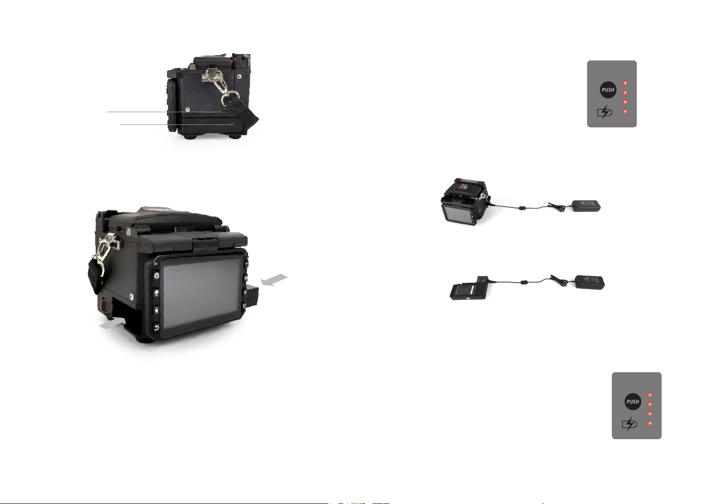
1110
Port of battery charge
MINI USB 2.0 Port
2.7 Power Supply Method
2.8 Charging Process
Following is the way of installing a battery.
Take out the battery
Insert the battery
Shut o fusion splicer.
Press on release button
at lateral, drawing power
supply unit out of the
fusion splicer.
Insert the battery into
the power unit dock until
it clicks into place.
The battery indicator will be illuminated one by one
along with increasing electric quality until battery is
fully charged upto 100%.
2.9 Charging Methods
When battery is connected with fusion splicer, charging method is as follows:
When battery is separated from fusion splicer, charging method is as follows:
Note: Try your best not to charge battery when the battery is working for the
running fusion splicer which is splicing or heating bers for fear of shortening the
battery’s life.
2.10 Battery Status
There are 2 ways for viewing battery level.
① If the battery is connected to the slicer, then its level will be
displayed on the upper right side of the screen.
② Battery level is indicated by Battery LED indicator. As shown
below:
BATTERY
INDICATOR
BATTERY
INDICATOR

1312
2.11 Battery Refresh Cycle
The battery should be refreshed or activated periodically for fear of aging caused
by battery memory eect. The method is as follows:
Keep the splicer in power-on status to discharge until the splicer switched o
automatically due to completely discharging. Then go on to charge until fully
charging completes. Battery refreshing process completes.
2.12 Heat Oven
Heat oven lid open
cooling tray
Chapter 3 Basic Operation
3.1 Power Connection
Follows are 2 ways of power supply for the fusion splicer, of which the inner slot
for power supply unit is able to support:
1. AC adapter, if external power source supply adopted;
2. Removable battery, if battery power supply adopted.
3.2 Battery Check
Before fusion splicer operation, Please check and ensure the residual electric quality
of the battery, which should be equal to 20% or more. Otherwise the battery is not
able to support fusion splicing and heating operations of the fusion splicer.( As to
the ways of electric quality check for battery, please refer to chapter2 for battery
status in detail)
1514
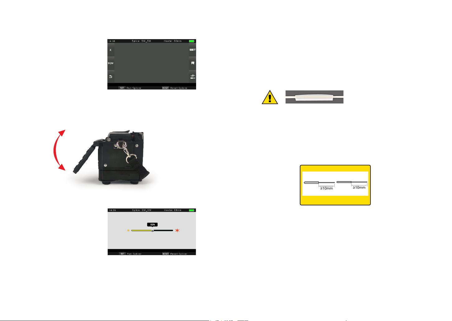
3.4 Adjust Monitor Position
Users can adjust the monitor position by moving it with a desired angle for the
clearest display.
3.5 Adjust LCD Backlight Brightness
Enter into Power save option
interface, and select LCD
Brightness option to adjust LCD
backlight brightness until you
nd the clearest position.
Note: The LCD monitor is a precise component produced by manufacturing factory
under strict quality control. However, some tiny dots in dierent colors may still
remain on the screen. Meanwhile, the screen brightness may not appear uniform,
depending on its viewing angles. Note that these symptoms are not defects, but are
natural phenomenon.
3.6 Preparing the Fiber
3 steps should be carried out before splicing:.
1.Stripping
Remove at least 50mm of secondary coating (valid for both tight and loose tube
secondary coating) and approximately 30~40mm of primary coating with an
appropriate stripper.
Note: always remember to slip a
heat-shrinkable sleeve onto either
end of the bers at the beginning
of each ber preparations.
2. Clean bare bers with pure alcohol-soaked gauze or lint-free tissue.
3. Cleave the ber
In order to ensure the best splicing result, cleave the bers with high quality cleaver
such as DC-09 ber cleaver, and strictly control the cleaving lengths shown as
below.
Important!
From this moment, you must be very careful with the bers to ensure that they do
not become dirty again.(For example, avoid putting them down on a dusty working
surface, or even waving them around in the air). Also check if the V-grooves are
clean, if not, wipe them clean.
3.3 Turn On the Splicer
Press [Power] key on the operation
panel, and wait the splicer to be
turned on and move to Workbench
page.
Examples of cleaving lengths
primary coating
use blue V-grooves
(Clamping on bare ber)
tight secondary
coating
1716
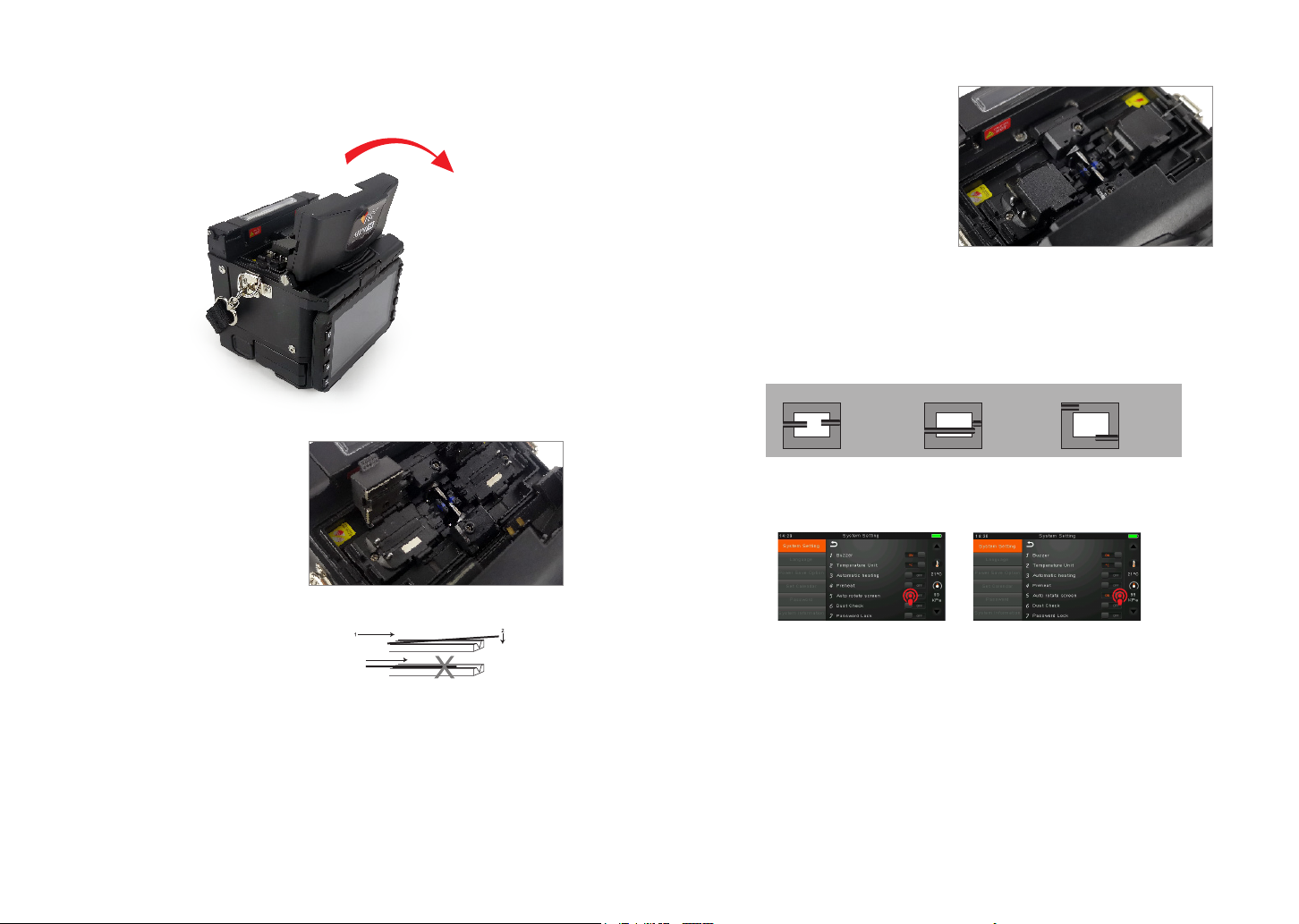
② Open the ber holder. Position
the bers into V-grooves. Make
sure the ber ends are between
the V-groove edges and the
electrode tip.
Note: Make sure to avoid sliding the
bers along V-grooves, but rather
position them over V-grooves and tilt
them down into place (as shown in the
picture).
③ Close the ber holder.
④ Close the wind proof cover
3.8 Inspecting the Fibers
① Before continuing with splicing, inspect the bers whether they are clean and
well-cleaved.
3.7 How to Make a Splice
① Open the safety shield.
a. b. c.
imaging area
ber ends visible
on the monitor
Fiber ends outside
monitor
Fiber ends
above and
below monitor,
not possible
to nd
automatically.
imaging area imaging area
② To change between Front View and Back View, adjust Monitor position.
Table of contents
Other FIBER FOX Welding System manuals


Popular Welding System manuals by other brands


TAFA
TAFA 30*8B35 owner's manual

Lincoln Electric
Lincoln Electric INVERTEC V350-PRO CE Technical specifications

ESAB
ESAB Buddy Arc 145 instruction manual

CIGWELD
CIGWELD 636804 use instructions

Red-D-Arc
Red-D-Arc DC-400 Operator's manual

Hobart Welding Products
Hobart Welding Products Spool Gun DP 3035-10 owner's manual


