STC SPACE SAVER 30504 User manual

Installation Manual
Mounting Systems
model # 30504
Low Prole Extends from 4.5” to 20.3“
Fits Displays from 30” to 55’’
Supports Up to 105 lbs (47.7 kgs)
Full Motion Wall Mount
For Flat Panel TVs
Systems Trading Corporation
450 7th Avenue, Suite 2809, New York, NY 10123

TABLE OF CONTENTS
1 of 13
www.stcny.com
!
!A WARNING alerts you to the possibility of serious injury or death if you do not follow the
corresponding instructions.
A CAUTION alerts you to the possibility of damage to or destruction of the equipment if you
do not follow the corresponding instructions.
Failure to provide adequate structural strength for this component can result in physical
injury and/or damage to equipment. It is the installer’s responsibility to make sure the
structure to which this component is attached can support four times the combined weight
of all equipment. Reinforce the structure as required before installing the component.
Improper installation can result in serious physical injury. This mount has been tested to
support 105 lbs (47.7 kgs.) Do not exceed that weight.
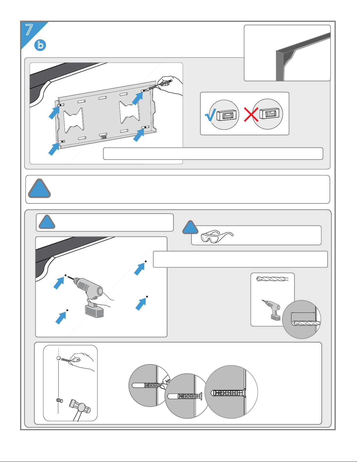
Safety measures must be observed at all times during the installation of this product. Use
proper safety gear and tools during the installation process to prevent physical injury.
Do not install on a structure that is prone to vibration, movement or chance of impact.
Doing so could result in damage to the at panel display and/or mounting surface.
Do not install near a heater, replace, direct sunlight or any other source of direct heat.
Doing so could result in damage to the at panel display and could increase the risk of re.
WARNING:
WARNING:
WARNING:
WARNING:
CAUTION:
CAUTION:
CAUTION:
warnings and cautions ..........................................................................
unpack
...................................................................................................................
required tools ...........................................................................................
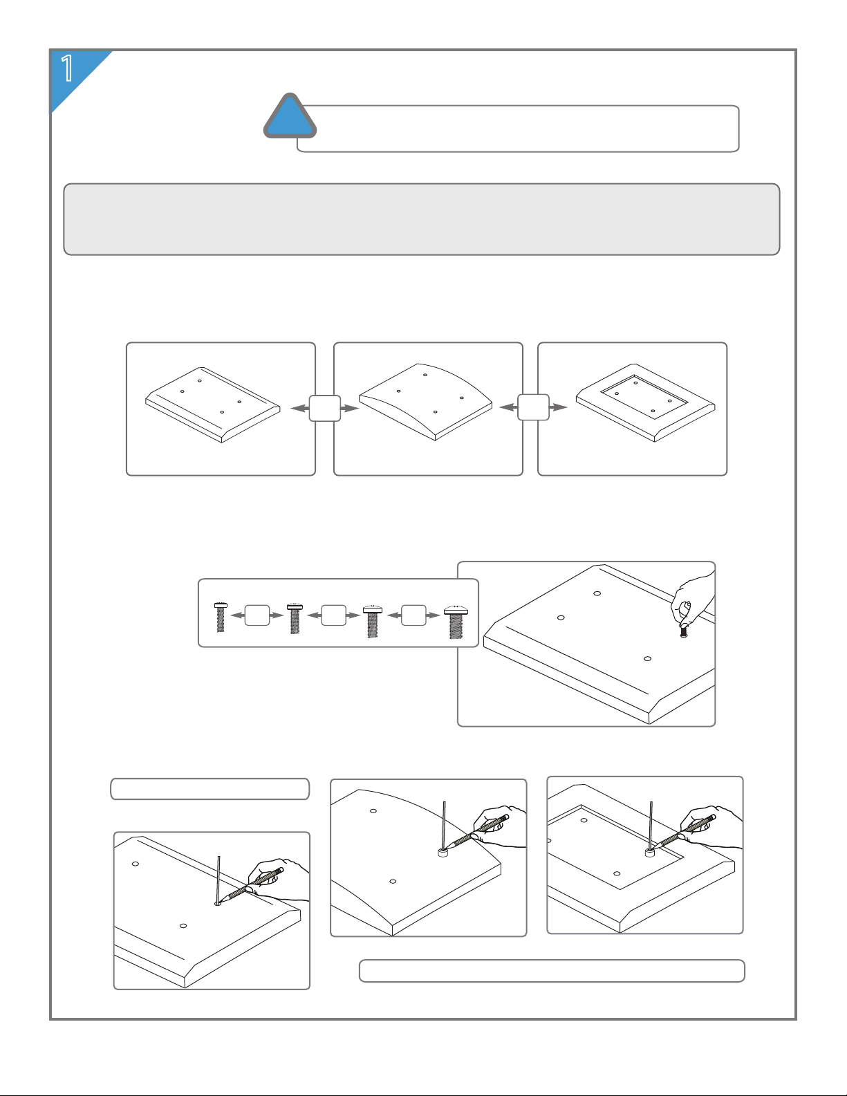
identify display back style, screw diameter and length ...........
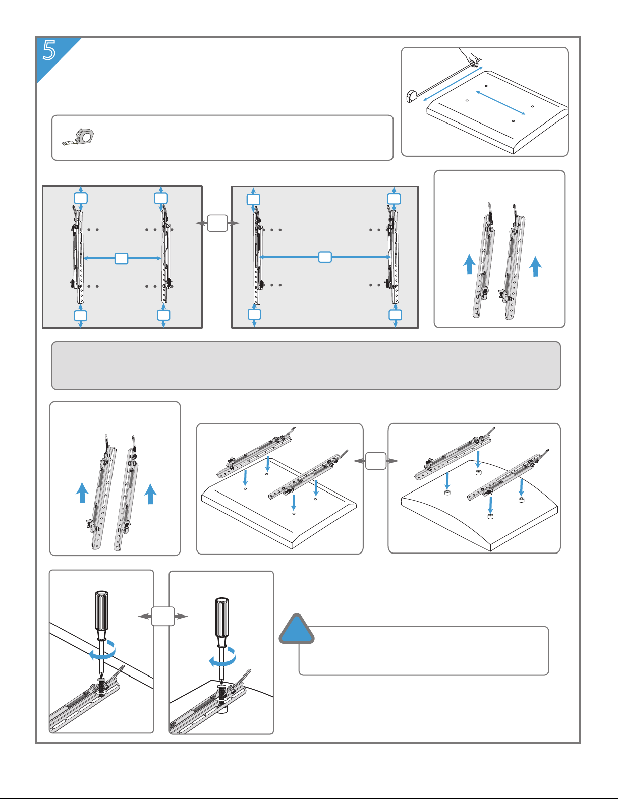
select and test components ................................................................
attach brackets to display .....................................................................
wall placement .........................................................................................
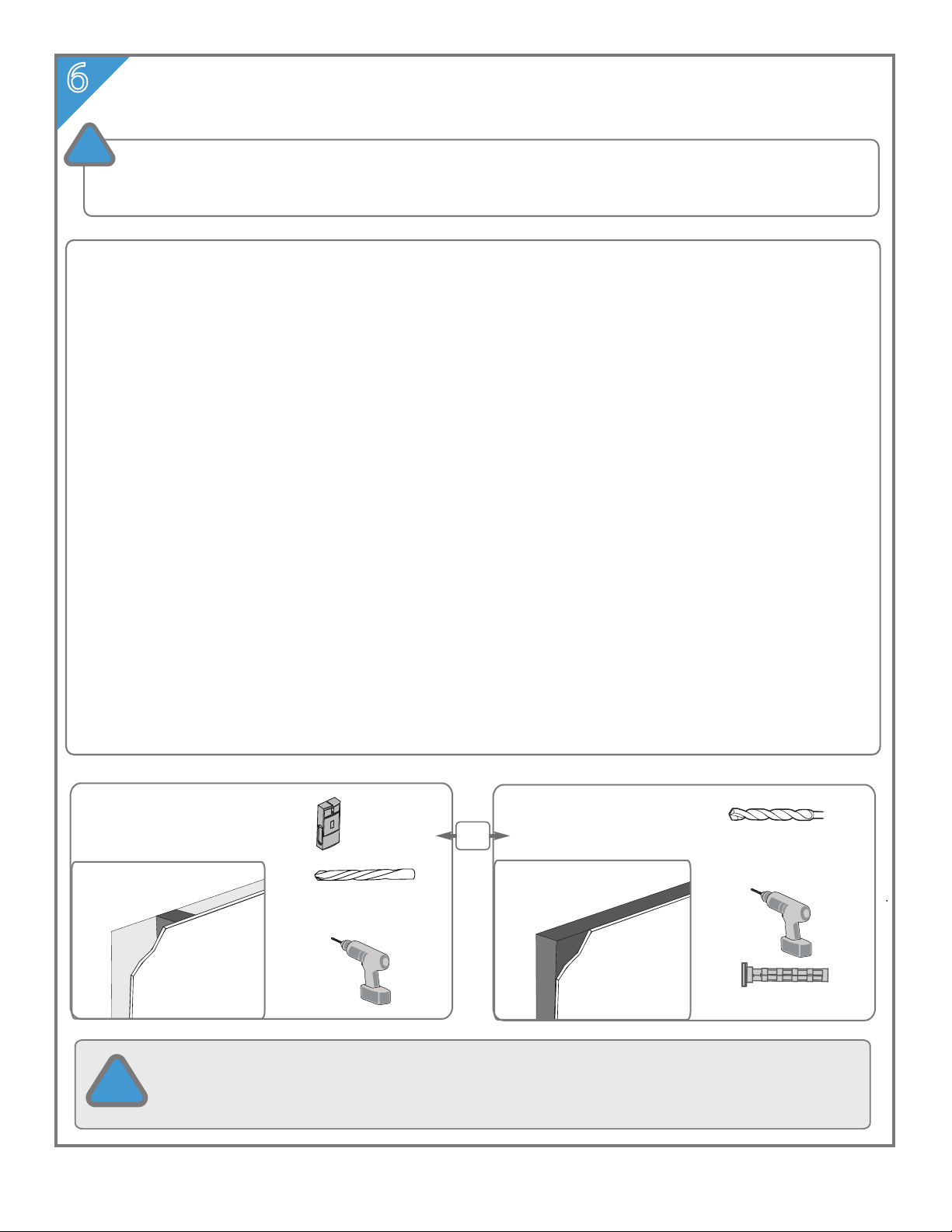
attach to wood stud ...............................................................................
attach to masonry walls ........................................................................
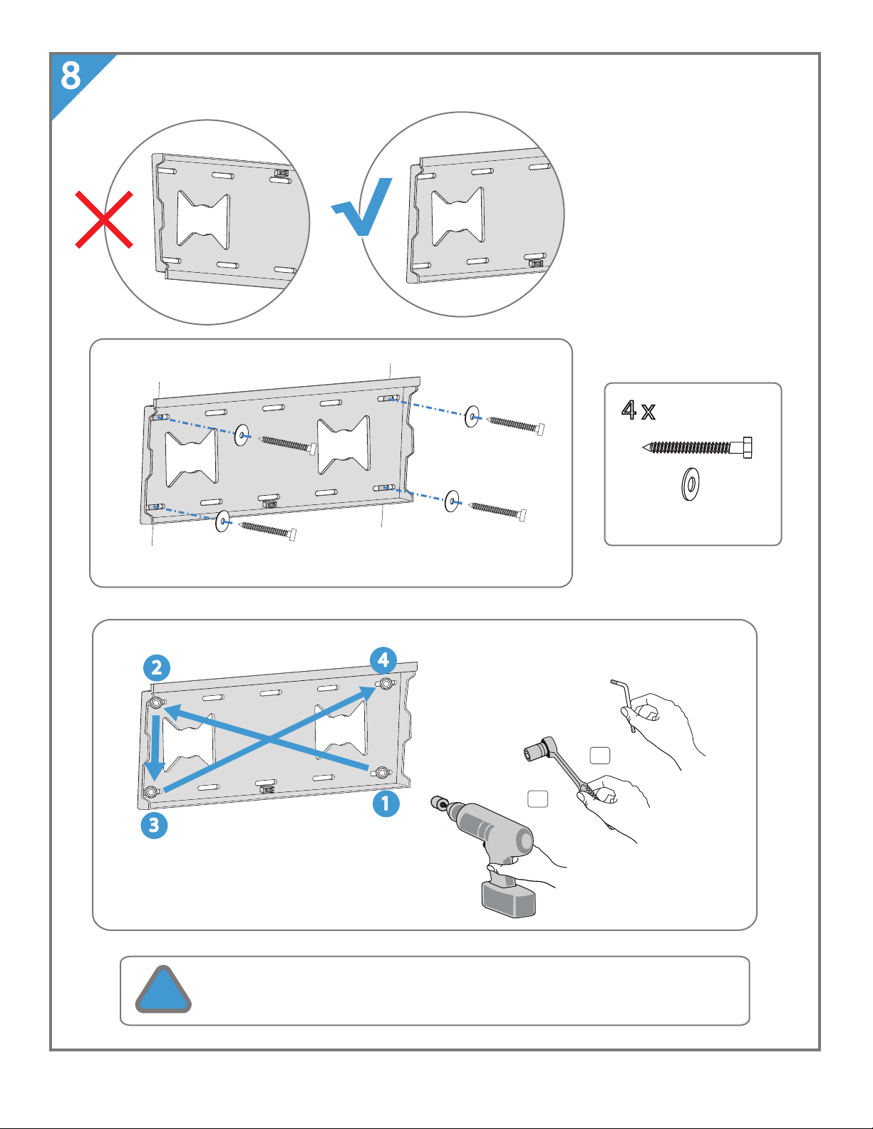
secure wall plate to wall ........................................................................
attach extension arm assembly to wall plate ...............................
mount display to wall plate .................................................................
secure display ............................................................................................
adjust ...........................................................................................................
warranty .....................................................................................................
1
2
2
3
4
5
6
7
8
9
10
11
12
12
13
BEFORE YOU BEGIN, MAKE SURE YOU CAREFULLY READ AND UNDERSTAND THE INSTRUCTIONS IN THIS
MANUAL. This bracket system incorporates a slip on mount design. Our goal is to make this installation
easy for you. Please follow the instructions in the order presented in this manual and be sure to observe
all warnings and cautions.
!
!IMPORTANT WARNINGS AND CAUTIONS!

required tools
unpack
Make certain the following installation hardware and components are included. If any of the parts are missing or
damaged please contact STC Customer Care at (800) 293-2923.
Parts are not shown actual size.
stud nder
phillips screw driver
2
1
tape measure
safety glasses
pencil
power
drill
5/32” (4mm) wood drill bit
or
1/4“ (6mm) + 3/8” (10mm) masonry drill bits
2 of 13
www.stcny.com
M8 x 40mm screw & washer
M6-M8 large spacer
M5-M6 medium spacer
spirit level
M6 x 16mm screw & washer
lag bolt & washer
M4 x 16mm screw & washer
M8 x 20mm screw & washer
M4 small spacer
M6 x 20mm screw & washer
M8 x 30mm screw & washer
M5 x 20mm screw & washer
nylon anchor
4mm allen key
knurled head screw
6mm allen key
right display bracket
left display bracket
wall plate
extension arm assembly
4 x
1 x
2 x

To ensure proper mounting of the brackets to your display, we have provided several sizes of screws
and spacers that can be used in combination. Combinations are determined by the display back style
(the area surrounding the mounting holes) and the diameter and depth of those holes.
3 of 13
www.stcny.com
1identify
Mark a toothpick or straw.
NOTE: Measure with spacer for displays with recessed backs.
at curved recessed
OR OR
display back style
!Unplug your display before you begin.
Invert the display and place it on a soft, padded, at surface.
select diameter
OR OR OR
M4 M5 M8M6
measure depth
at
curved recessed

4 of 13
www.stcny.com
2select
3test
OR
at
at
curved recessed
OR
OR
CAUTION: When screw is longer than mark, choose a shorter
screw. Several lengths have been provided for this reason.
M4
M5
M8
M6
CAUTION: When screw is longer than mark, choose a shorter
screw. Several lengths have been provided for this reason.
curved
recessed
OR
at
M4
M5
M8
M6
Gently test all fasteners together, screwing them in by hand
to ensure proper t. Do not tighten. If there is any resistance,
remove immediately and select alternate fasteners.
!

b
a
b
a
5 of 13
www.stcny.com
5attach
Tighten screws so brackets are rmly attached.
DO NOT OVER TIGHTEN. Over tightening may
damage your display.
!
Center brackets vertically to back of display.
Measure the horizontal width between holes.
Bracket placement for
maximum width d.
Bracket placement for
maximum width c.
a = b
c = between 3.9 “ (100mm) to 22.5” (575mm)
d = between 22.6” (576mm) to maximum 26.3” (668mm)
2
1
NOTE: The following steps illustrate attaching the brackets for maximum width c. When your
maximum width is d, reverse bracket placement so the top adjustment faces the inside as shown
above. Follow instructions to attach to display and mount. See step 13 for adjustment instructions.
top
left top
right
top
left top
right
OR
OR
b
a
b
a
c
at
at
curved or recessed
curved or recessed
OR
d

6wall placement
Wall Placement:
When selecting a wall to mount your display, keep the following in mind:
• Select a place with easy access to power outlets, cable input sources, and connections for speakers and accessories.
• Avoid direct sunlight, heat and vibrations and do not place in direct ow of trac.
• SELECT A WEIGHT BEARING WALL. The wall must be able to safely support four times the combined load of the
equiptment and all attached hardware and components.
Mounting Height:
The optimal viewing height is to center the display at eye level when seated. Many people consider this to be too low
for a wall mount, and commonly use the following rule for placement:
Position the bottom of the display no higher than eye level when seated, and the top of the display no higher than
eye level when standing. Anything within these limits should normally provide a comfortable viewing experience.
Wall Suitability:
The hardware included is suitable for mounting to walls made of brick, solid concrete, concrete block or wood studs
covered with drywall. If your mounting situation is dierent, please consult a qualied installer or contact STC Customer
Care at (800) 293-2923.
Wall Stability:
Carefully inspect the wall area you have selected. Examine the wall surface before you begin drilling.
• For concrete walls, check for damaged or loose concrete and do not drill in those areas.
• For brick or concrete block, never drill into the mortar between blocks.
• For wood studs, locate the wall studs and drill in the center of the stud.
• DO NOT DRILL NEAR ELECTRICAL WIRING AND WATER PIPES.
IMPORTANT: MAKE SURE THE WALL IS A WEIGHT BEARING WALL.
CAUTION: Failure to observe all safety precautions can result in serious physical injury and/or property
or (800) 293-2923 if you have any questions.
!
BEFORE YOU BEGIN, MAKE SURE YOU CAREFULLY READ AND UNDERSTAND THE INSTRUCTIONS IN THIS MANUAL.
This bracket system incorporates a slip on mount design. Our goal is to make this installation easy for you. Please
follow the instructions in the order presented in this manual and be sure to observe all warnings and cautions.
!
6 of 13
www.stcny.com
wood stud masonry
Ø 5/32” (4 mm)
wood drill bit
stud nder Ø 1/4” (6 mm)
Ø 3/8” (10 mm)
masonry drill bits
nylon anchor
OR

7solid wood stud
(2” x 4”)
Use commercially available stud nder to locate stud centers.
7 of 13
www.stcny.com
Ø 5/32” (4 mm)
wood drill bit
!
Avoid drilling near electrical wiring and water pipes. Mount must be attached to a weight bearing wall
and must be installed directly onto center of wood stud. Failure to observe all safety precautions can
result in serious physical injury and/or property damage. Consult a professional installer or call STC
Customer Care at (800) 293-2923 if you have any questions.
a
attach wall plate
to wood stud
!CAUTION: Wear safety glasses
when operating power tools.
3”
(76 mm)
Use built in level. Position wall plate so bubble is centered. Mark holes as shown.
Use 5/32” (4 mm) wood drill bit to drill 3“ (76 mm) pilot holes.
Then proceed to step 7.

7
8 of 13
www.stcny.com
attach wall plate
to masonry walls
b
brick, concrete block or
solid concrete (3000 psi)
Ø 1/4” (6 mm)
Ø 3/8” (10 mm)
masonry drill bit
!CAUTION: Wear safety glasses
when operating power tools.
!Do not drill into mortar between bricks or
concrete blocks or into loose concrete.
Avoid drilling near electrical wiring and water pipes. Mount must be attached to a weight bearing wall.
Failure to observe all safety precautions can result in serious physical injury and/or property damage.
Consult a professional installer or call STC Customer Care at (800) 293-2923 if you have any questions.
!
Insert anchors. Use hammer until completely ush to concrete
surface, even if covered by a layer of drywall or other material.
3”
(76 mm)
Use 1/4” (6 mm) masonry drill bit to slowly drill 3“ (76 mm) pilot holes.
Then use 3/8” (10 mm) masonry drill bit to expand pilot holes.
Use built in level. Position wall plate so bubble is centered. Mark holes as shown.

secure wall plate
8
9 of 13
www.stcny.com
OR
OR
Tighten lag bolts so wall plate is rmly attached. DO NOT OVER TIGHTEN.
Over tightening can damage screws and greatly reduce holding power.
!
4
3
2
1
4 x
lag bolt and washer
6mm
hex key

11 of 13
www.stcny.com
Position brackets anywhere between
both ends of the VESA plate.
Position brackets anywhere between both ends of the front plate.
!
Use two or more people
when lifting display.
11 mount
!Make sure both brackets are rmly
tightened to tilt in the center position.
Carefully lower display on the front
plate of assembly arm extension.
Make sure the brackets hook onto top
and bottom edges of the front plate.

12
13
12 of 13
www.stcny.com
secure
adjust
Secure both display brackets to bottom of extension arm assembly front
plate with phillips screw driver.
Secure both display brackets to bottom of extension
arm assembly front plate with phillips screw driver.
!
Use two or more people
when adjusting display.
Tilt display from level
to minus 15 degrees.
Tighten screws rmly when you nish. DO NOT OVER TIGHTEN.
!
Loosen screw on display brackets to rotate
and adjust tilt.
NOTE: When brackets are positioned for
maximum width as shown in step 5, loosen
screw on inside to rotate and adjust tilt.
Mount pivots 180 degrees at each joint.
/15 ºº
0
Hold display before loosening screws. Continue
to hold until you have tightened the screws again.
!
Tighten screws rmly. DO NOT OVER TIGHTEN. Overtightening
can damage bolts and greatly reduce holding power.
!

STC warrants that it will replace or repair this item, free of charge,
at STC's sole discretion, should it prove defective in materials or
workmanship.
If a claim is made under this warranty, the mount should be
returned, freight prepaid, with the original purchase receipt to
your dealer or to a Space Saver distributor.
This warranty does not apply to:
• Normal wear and tear
•Friction damage
•Coating defects
•Defects caused by loosened screws, nuts or bolts
•Improperly mounting the bracket to the wall
•Improperly installing the bracket to the display
•Failure to properly follow installation instructions
•Modication or repairs not made or authorized by STC
•Loading beyond permitted load
•Intentional misuse
LIFETIME WARRANTY
Copyright © 2008, Systems Trading Corporation, All rights reserved.
13 of 13
www.stcny.com
Systems Trading Corporation
450 7th Avenue, Suite 2809, New York, NY 10123
Table of contents
Popular TV Mount manuals by other brands

ricoo
ricoo FS0344 quick start guide

Mounting Dream
Mounting Dream MD2463-02 Installation instruction

United States Stove Company
United States Stove Company USLRK Assembly instructions

Kanto
Kanto T3760 user manual

Cotytech
Cotytech DM-C1SA2 installation manual

Mounting Dream
Mounting Dream MD2380-03 installation instructions