Steamtec AIO User manual

_________________________________________________________________________________
TOLO SAUNA info@tolosauna.com www.tolosauna.com
1
Steamtec AIO
Steam Generator Manual
DO NOT use locking pliers to over tight the
DRAIN PIPE connection
Please read the manual carefully before installation
and keep the manual for further reference
_________________________________________________________________________________
TOLO SAUNA info@tolosauna.com www.tolosauna.com
2
Table of Contents
1. Configuration List........................................................................................................................................................ 3
2. Introduction.................................................................................................................................................................4
3. Safety Warning............................................................................................................................................................ 5
4. Install Cautions............................................................................................................................................................ 5
5. Parameters.................................................................................................................................................................. 6
5.1. Models, parameters and dimension................................................................................................................6
5.2. Steam generator construction......................................................................................................................... 7
5.3. Controller parameters and dimension.............................................................................................................8
6. Installation And Cautions............................................................................................................................................ 9
6.1. Installation cautions.........................................................................................................................................9
6.2. Installation of steam generator body.............................................................................................................. 9
6.2.1. Cautions................................................................................................................................................ 9
6.2.2. Installation.............................................................................................................................................9
6.3. Installation of Central function box............................................................................................................... 10
6.4. Installation of controller and temperature sensor........................................................................................ 12
6.5. Installation of pipeline................................................................................................................................... 16
6.6. Installation of electrical circuit.......................................................................................................................18
6.6.1. Power Supply...................................................................................................................................... 19
6.6.2. Wire Diagram...................................................................................................................................... 19
7. Functions And Operation.......................................................................................................................................... 25
7.1. Control panel display items........................................................................................................................... 25
7.2. Auto Functions............................................................................................................................................... 30
8. Maintenance............................................................................................................................................................. 31
9. Troubleshooting........................................................................................................................................................ 32
10. Warranty And Services............................................................................................................................................34
11. Appendix: Parameter Of Special Models.............................................................................................................35
MAINTENANCE RECORD(Regular descaling records)................................................................................................... 36
_________________________________________________________________________________
TOLO SAUNA info@tolosauna.com www.tolosauna.com
3
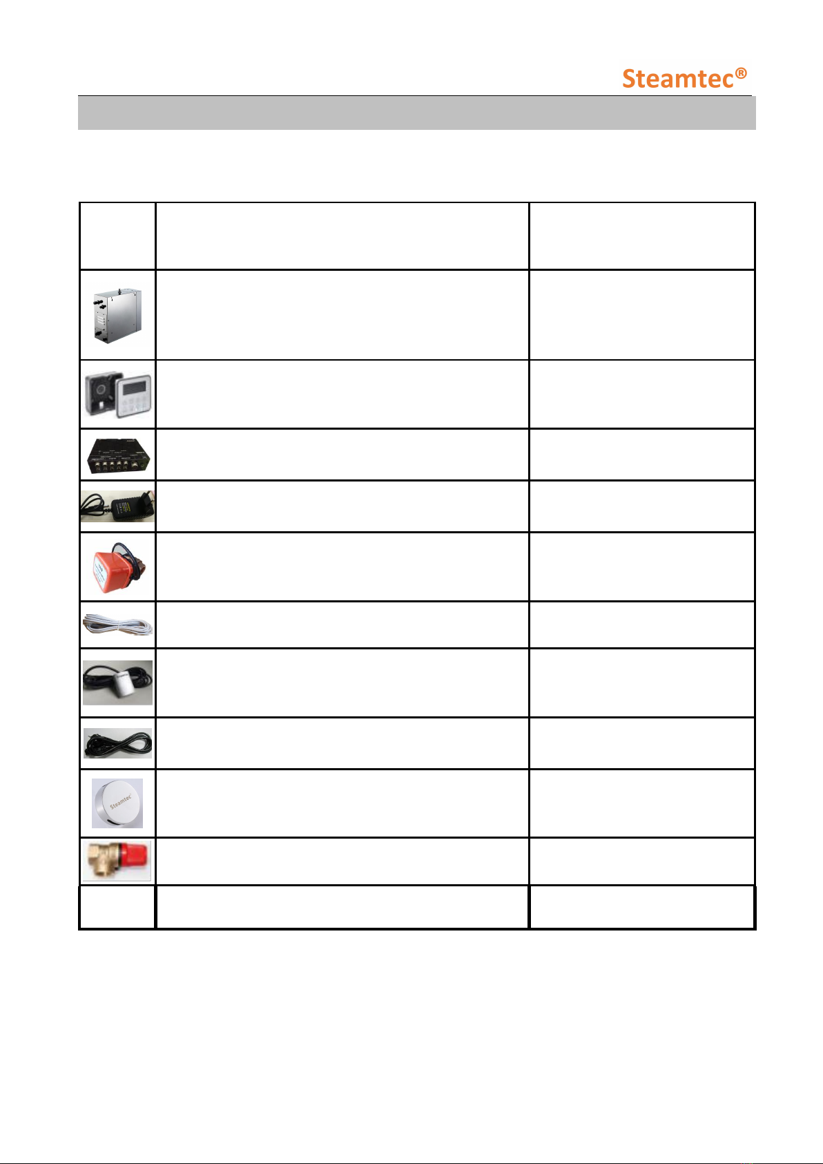
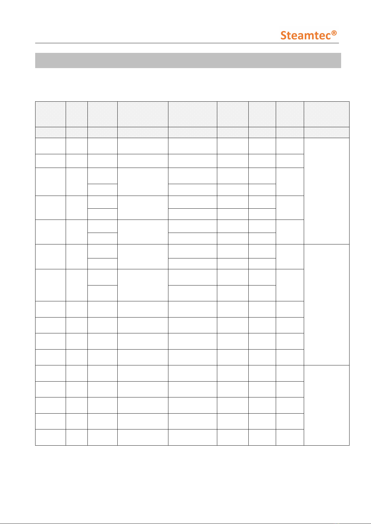
1. Configuration List
When receive the steam generator, please check if you have get complete set according to below
chart or not, contact us immediately if any missing.
Table 1
Photos
Item name
Quantity
Steam generator in stainless steel housing
1pc
Controller+housing box, waterproof touch screen
1set
Central function box
1pc
Central function box power cord
1pc
3/4" Full-bore straight auto drain valve
1pc
Control cable, length 5 m (central function box ->
controller)
1pc
Temp sensor with box, length 5 m (central function
box -> sensor end position)
1pc
Central function box cable (steam generator -> central
function box)
1pc
Stainless steel#304 steam nozzle
1pc for 3kw~13.5kw;
2pcs for 15kw~24kw
Safety valve
1pc
English User Manual
1pc
_________________________________________________________________________________
TOLO SAUNA info@tolosauna.com www.tolosauna.com
4
2. Introduction
Thank you for choosing “Steamtec” AIO series steam generator with well-designed structure,
steady performance and convenient installation. This steam generator can work with the steam
room, to form a whole steam-bath system. The steam-bath is for removing tiredness, relaxing
muscles and stimulating blood circulation.
For proper installation, operation, maintenance, and the safety of customer as well, please read all
instructions carefully and keep this manual for further reference.
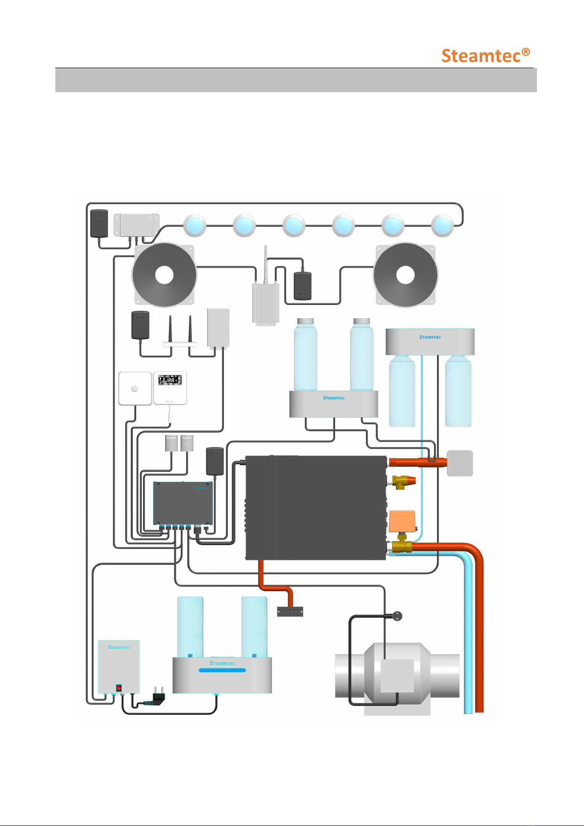
Figure 1 The whole AIO steam bath system
_________________________________________________________________________________
TOLO SAUNA info@tolosauna.com www.tolosauna.com
5
3. Safety Warning
This appliance is not intended for use by person with reduced physical, sensory or mental
capabilities, under 16 years old, or lack of experience and knowledge, unless they have
been given supervision or instruction concerning use of the appliance by a person
responsible for their safety.
Children should be supervised to ensure that they do not play with the appliance.
Check steam room before restart the controller.
Smoking and alcohol are not allowed inside the steam room.
Leave the steam room immediately when feels uncomfortable.
A ventilation fan is required for the steam room.
This steam generator is for heating up the steam room, please don’t change its functions or
usage by yourself, unless under the help or the guide of someone who can be responsible
for the safety.
When you go out, or may not use the steam generator in long time, please DISCONNECT
the steam generator general power supply and general water supply.
4. Install Cautions
If the generator is installed at a place where difficult for customer access, the water supply
valve must be easy to access for emergencies.
GFCI must be installed on the power supply, and the power supply, power wire, fuse and
breaker must comply with the nameplate on the unit and table 2 in this manual.
The solenoid valve can endure maximum 0.8MPa (8kg/cm2) water pressure. To protect the
solenoid valve from extremely high water pressure, please turn down the inlet slightly or install
water pressure relieving valve.
Do not install saddle-backed or needle valves on the inlet. Please dredge and clean the pipe
before installation.
No block valve should be installed in the steam pipelines. Strictly no blocked or blended pipe,
otherwise have negative effect on the flow of steam and condensate. The steam pipelines
should be installed with a slight angle so that the condensate can flow back to the generator or
the steam head.
Steam generator should be installed indoor to avoid frozen. The generator should be installed
and leveled with the arrow pointing upward at an easy-access place, otherwise do not switch
on.
The steam pipeline must be copper pipes or stainless steel pipes, all other material such as
plastic, acrylic should not be used since they cannot endure 150℃or higher temperature.
All inlet and apertures should be sealed to prevent any leakage of steam and to protect the
generator and customers.
Don’t drain water to the steam room from the water tank as may cause serious scald and
damage the steam room.
All inlet water pipes and steam pipelines should be built according to the National Standard
and this should be done before sealing the wall.
_________________________________________________________________________________
TOLO SAUNA info@tolosauna.com www.tolosauna.com
6
5. Parameters
5.1. Models, parameters and dimension
(Only apply to European style voltage and phase)
Model
Power
Phase
Heating elements
Voltage / Current
Power wire
Breaker
Room
volume
Dimension
(L*W*H)
kW
N
N*KW
V/A
N*mm2
A
m3
mm
TOLO-30
3.0
1
2*1.5
215-240/13.6
3*2.5
16
2~3
425*160*315
TOLO-40
4.0
1
2*2.0
215-240/18.2
3*2.5
25
3~5
TOLO-45
4.5
1
3*1.5
215-240/20.5
3*2.5
25
3.5~
5.5
3
380-415/6.8
5*1.5
16
TOLO-50
5.0
1
2*1.5+1*2.0
215-240/22.7
3*2.5
32
4~6
3
380-415/9.1
5*1.5
16
TOLO-60
6.0
1
3*2.0
215-240/27.3
3*4.0
40
5~7
3
380-415/9.1
5*1.5
16
TOLO-70
7.0
1
2*2.5+1*2.0
215-240/31.8
3*6.0
40
5.5~8
475*185*450
3
380-415/10.6
5*2.5
16
TOLO-75
7.5
1
3*2.5
215-240/33.75
3*6.0
60
6.5~9
3
380-415/11.25
5*2.5
16
TOLO-90
9.0
3
6*1.5
380-415/13.6
5*2.5
16
8~11
TOLO-105
10.5
3
3*1.5+3*2.0
380-415/15.9
5*2.5
25
9~12
TOLO-120
12.0
3
6*2.0
380-415/18.2
5*2.5
25
11~14
TOLO-135
13.5
3
3*2.0+3*2.5
380-415/20.25
5*2.5
32
12~15
TOLO-150
15.0
3
6*2.5
380-415/22.7
5*2.5
32
13~18
510*185*460
TOLO-165
16.5
3
6*2.0+3*1.5
380-415/24.75
5*4.0
40
14~20
TOLO-180
18.0
3
9*2.0
380-415/27.3
5*4.0
40
16~22
TOLO-225
22.5
3
9*2.5
380-415/34.1
5*6.0
60
19~26
TOLO-240
24.0
3
6*2.5+3*3.0
380-415/36.4
5*6.0
60
22~30
Table 2
_________________________________________________________________________________
TOLO SAUNA info@tolosauna.com www.tolosauna.com
7
Notice:
The rated power is measured under single phase 230V, therefore the actual operating power
under single phase 215-240V, 50/60Hz, or three phases 380-415V, 50/60Hz may be different
from the rated value.
3KW and 4KW machine, can be only under 215-240V single phase. Please note the earth wire
should not less than 1.5mm2.
From 4.5KW to 8KW machine, can be made as 215-240V single phase or 380-415V three phases.
Please note the earth wire should not less than 1.5mm2, the live wire and null wire should not
less than 2.5mm2.
More than 9KW machine, can be only under 380-415V three phases. Please note the earth wire
should not less than 2.5mm2, the live wire and null wire should not less than 4.0mm2.
How to choose the right KW steam generator?
Step One: Calculate the steam room m³, (Length*Width*Height) in meter.
(1 feet = 0.3048 meter,1 inch=0.0254 meter)
Step Two: Check your steam room materials
If Acrylic, steam generator KW= steam room m³
If Ceramic Tile, steam generator KW= 1.30 X steam room m³
If All Glass tile or Glass Block Walls, steam generator KW= 1.35 X steam room m³
If Porcelain tile, steam generator KW= 1.6 X steam room m³
If Natural stone tiles* up to 1/2″, steam generator KW= 2 X steam room m³
If Natural stone slabs over 1/2″, steam generator KW= 2.25 X steam room m³
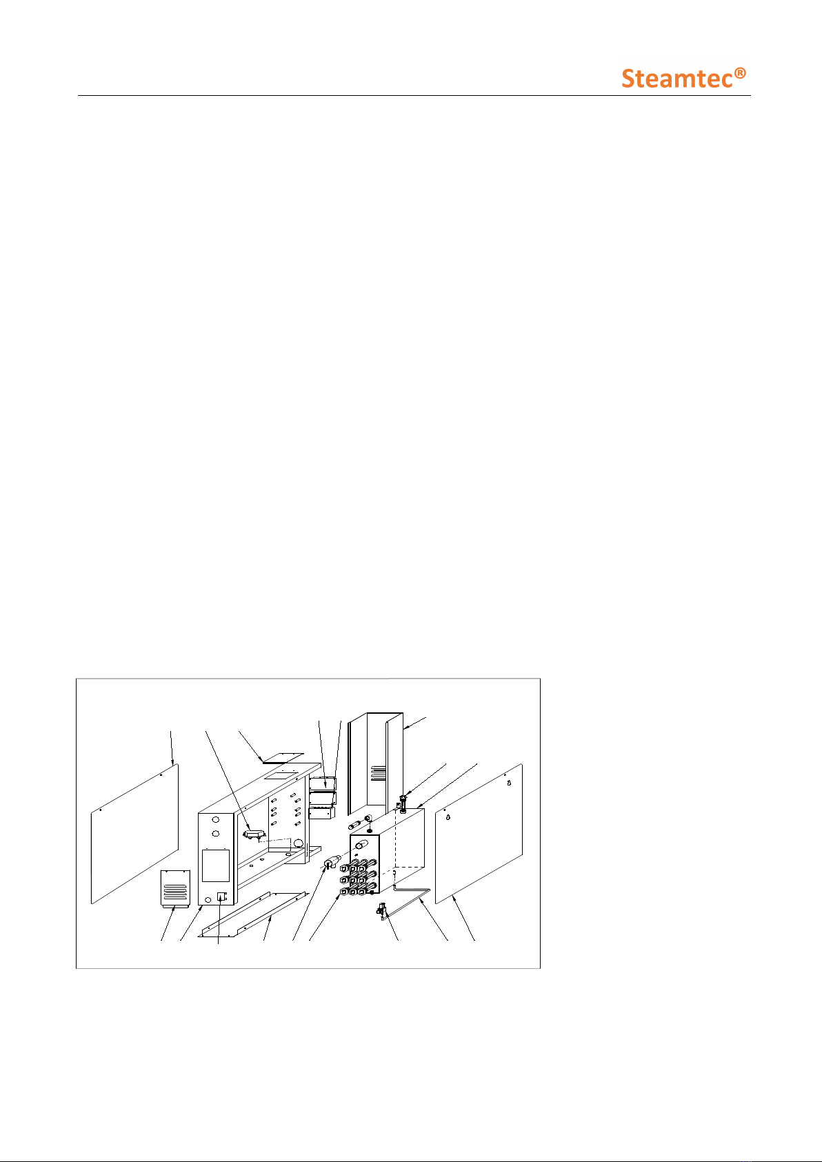
5.2. Steam generator construction
1
18 17 16 15
32 456
8 9 10
14 13 12 11
7
16. Base plate 17. Drain valve 18. Element access cover
Figure 2 Steam generator structure chart
1. Front Cover
2. Wire entry hole
3. Small cover
4. Sub-board(relay board)
5. Wire terminal
6. U shape cover
7. Water inlet position
8. Steam outlet
9. Water level sensor
10. Inner tank
11. Black Cover
12. Water inlet hose
13. Solenoid water inlet
valve
14. Heating elements
15. Safety valve

_________________________________________________________________________________
TOLO SAUNA info@tolosauna.com www.tolosauna.com
8
1
2
3
4
65
12
9
7
8
10 11
13
14
Figure 3 Steam generator schematic diagram
5.3. Controller parameters and dimension
Controller
model
Controlling time
range (minutes)
Temperature
showing range
Temperature
controlling range
Dimension
(mm)
AIO
1~60 or long-term
(CH)
6~60℃
(43℉~140℉)
35~60°C
(95℉~140℉)
103*103*45
Table 3
Notes:
AIO Controller can be installed inside the
steam room.
However, we recommend you to install the
controller outside the steam room to extend
its service life.
Figure 4 AIO controller
1. Steam outlet
2. Safety valve
3. Heating elements
4. Solenoid water inlet
valve
5. Drain valve
6. Drain pipe
7. High-temperature
protection
8. Wire terminal
9. Sub-board (relay)
10. Water level sensor
11. Temperature sensor
12. Inner water tank
13. Central box 14. Controller
_________________________________________________________________________________
TOLO SAUNA info@tolosauna.com www.tolosauna.com
9
6. Installation And Cautions
6.1. Installation cautions
DO NOT use locking pliers to over tight the DRAIN PIPE connection.
Before installation, MUST read all the install Cautions in this manual, on page 5.
Selecting the proper steam generator
In order to achieve comfort and relaxation, as well as energy efficiency, the selection of the correct
steam generator model and size are as critical as design of the steam room itself. The power supply
and circuit protector should be carefully checked to match the parameters of the generator. Please
referring to the table 2 & its notice and select the suitable model for your specification.
6.2. Installation of steam generator body
6.2.1. Cautions
Switch off all power supply before installation, and check whether you have the correct model for
your steam room according to table 2 & its notice.
Do not install the generator outdoors, in wet/moist place, freezing, or corrosive place. Do not
install the generator near to inflammables such as oil paint, diluents and fuel. Be alert to the
steam pipeline and safety valve since the high temperature of steam is dangerous to customers.
Generator must be level installed.
The generator should be installed in a dry and well-ventilated place. It can be installed either on
the wall or on the ground, but must be well fixed. Install the generator to steam room as close as
possible, such as in the closet, under the washing basin or in the basement. (Refer to figure 5).
6.2.2. Installation
i. Install the generator on the wall: drill two small holes with diameter of 8mm on the wall, insert
the expansion screws and then hang the generator on those screws.
ii. Install the generator on the ground or deck: install a frame on the site and then screw the
generator into the frame.
iii. Central function box should be installed near to the steam generator as near as possible, as the
length of the cable (connecting the steam generator and the central function box) is 50cm.
Please don’t use other extended cable, only the cable we provided is allowed.
iv. For better service and maintenance, please install the generator with the nameplate face to
front and leave more than 250mm space around the generator.

_________________________________________________________________________________
TOLO SAUNA info@tolosauna.com www.tolosauna.com
10
Install in the roof
Install in
the closet
Install in the basement
Install under the
washing basin
Suitable
for installation
Figure 5 Places to install steam generator
6.3. Installation of Central function box
Central function box should be installed near
to the steam generator, as the cable for
connecting the central function box and the
steam generator is only 50 cm.
Please hang the central function box on the
wall.
It need separate power supply, it’s provided
with plug.
Connect the function equipment (Like aroma
pump, color lights etc) to the central function
box respectively.
Figure 6 Central function box
Size :18*14*5CM

_________________________________________________________________________________
TOLO SAUNA info@tolosauna.com www.tolosauna.com
11
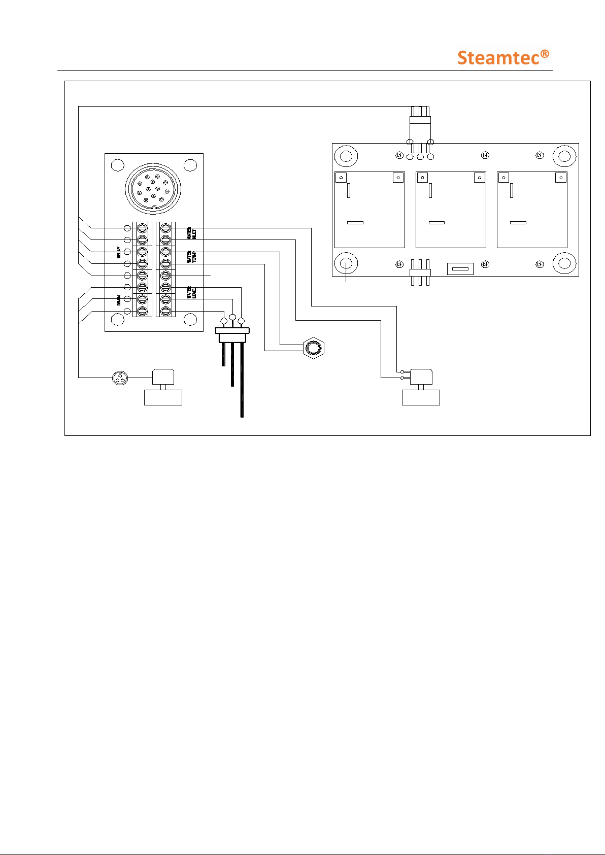
Figure 7 Central function box connectors
1. APP
2. Steam room temperature sensor
3. Controller
4. Steam room humidity sensor
5. Fast steam switch
6. Fan
7. Color lights
8. Salt spray generator
9. Aroma pump
10. Descaling pump
11. Connector to the steam generator
12. Power supply 12V DC
Connect the steam generator with the central function box by using the 12-core cable we provided.
Please install the central function box near to the steam generator as close as possible.
Please note the 12-core cable can’t be extended, and only from original factory is allowable.
NOTES: (indicators explanation)
D34: Main board power supply indicator
D39: Relay contact on-off state indicator
D24: Water level detection signal indicator
D18,D19,D20: Heating indicator
_________________________________________________________________________________
TOLO SAUNA info@tolosauna.com www.tolosauna.com
12
GND
GND
temperature
sensor for water tank 1
2
dc-12v water inlet valve
dc-12v drain valve
1
2 3
COM
NO
2
31
3 1
64
5
2
3
1
6
3
5
4
1
cathode
COM
NO NO
COM
white
blue
red
Figure 8 Steam generator 12-core cable socket corresponding functions
6.4. Installation of controller and temperature sensor
6.4.1. Cautions
The control wire and temperature wire should not be parallel to or intersect with the power
wire. The temperature sensor should NOT be installed on the side of the wall which is behind
the door.
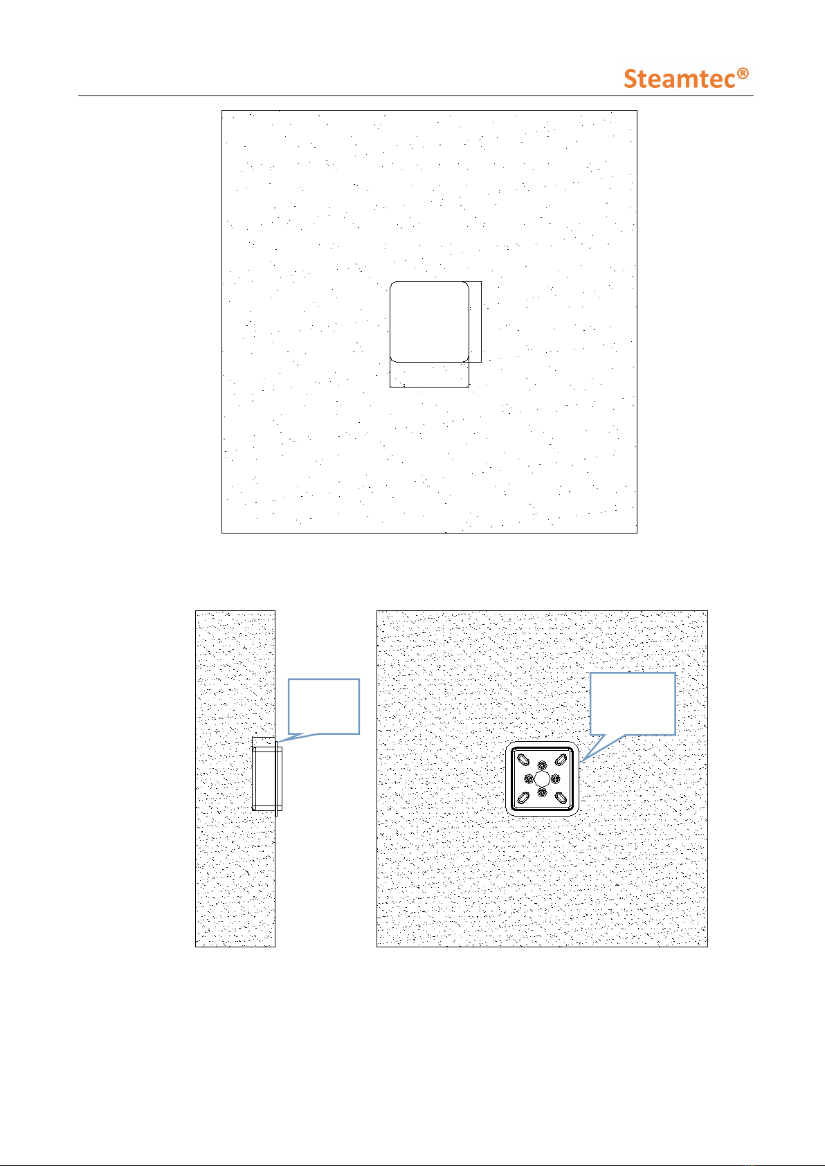
6.4.2. Installation of controller
The controller should be installed with height of 1.2 m inside or outside the steam room but
nearby or other place where easy to operate. Firstly follow below 4 steps for install housing
box, then pull the control wire through the conduit, then connect the control wire to the
central function box. Finally the controller can be insert to the housing box on the wall (Refer
to figure 9).
Steps for install housing box:
_________________________________________________________________________________
TOLO SAUNA info@tolosauna.com www.tolosauna.com
13
95.1
95.1
First step: open the hole on wall :95*95MM Depth:34MM
34
Second step: Housing box into the wall at the gap, horizontal installation
The gap for
Positioning
The gap for
Positioning
_________________________________________________________________________________
TOLO SAUNA info@tolosauna.com www.tolosauna.com
14
Third step: make the tiles cover the gap and keep in line with tiles
Forth step: insert the controller into the housing box
Tile molding
surface
Tile molding
surface

_________________________________________________________________________________
TOLO SAUNA info@tolosauna.com www.tolosauna.com
15
Real picture
Figure 9 Controller installations
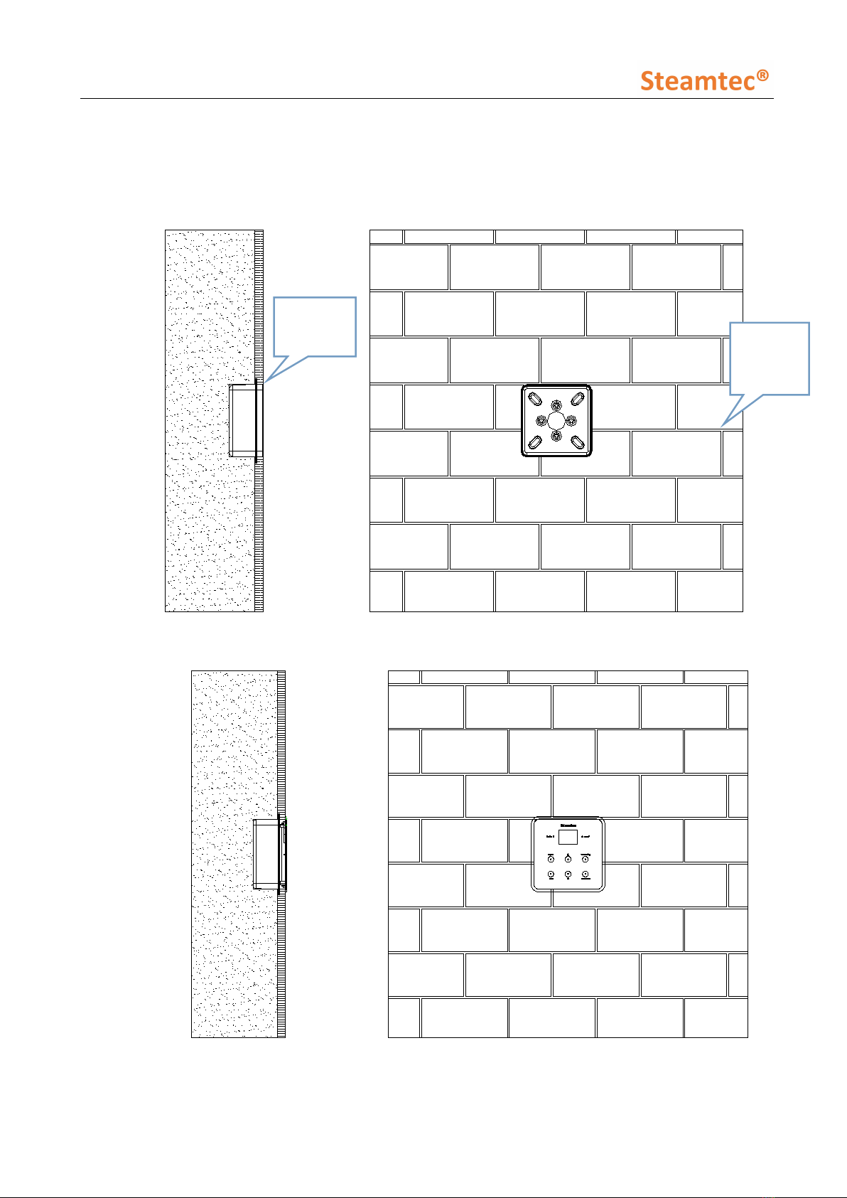
6.4.3. Installation of temperature sensor
The temperature sensor is used to
measure the temperature inside the
steam room, so that the generator can
work automatically according to the
pre-set temperature and maintain the
room temperature constant.
The installation height of the sensor
should be about 1.2 –1.5 m from ground.
Please drill a hole (diameter 16mm ), and
then nail down the sensor in the steam
room (Refer to figure 10), pull the sensor
wire through the conduit then connect
to the central function box.
wire pipe
control wire control wire
wire pipe
housing box
KSA-EA
controller
wall
Ceiling
wall
Temp.sensor
box
M4 self-tapping
screw
Figure 10 Temp sensor installations
_________________________________________________________________________________
TOLO SAUNA info@tolosauna.com www.tolosauna.com
16
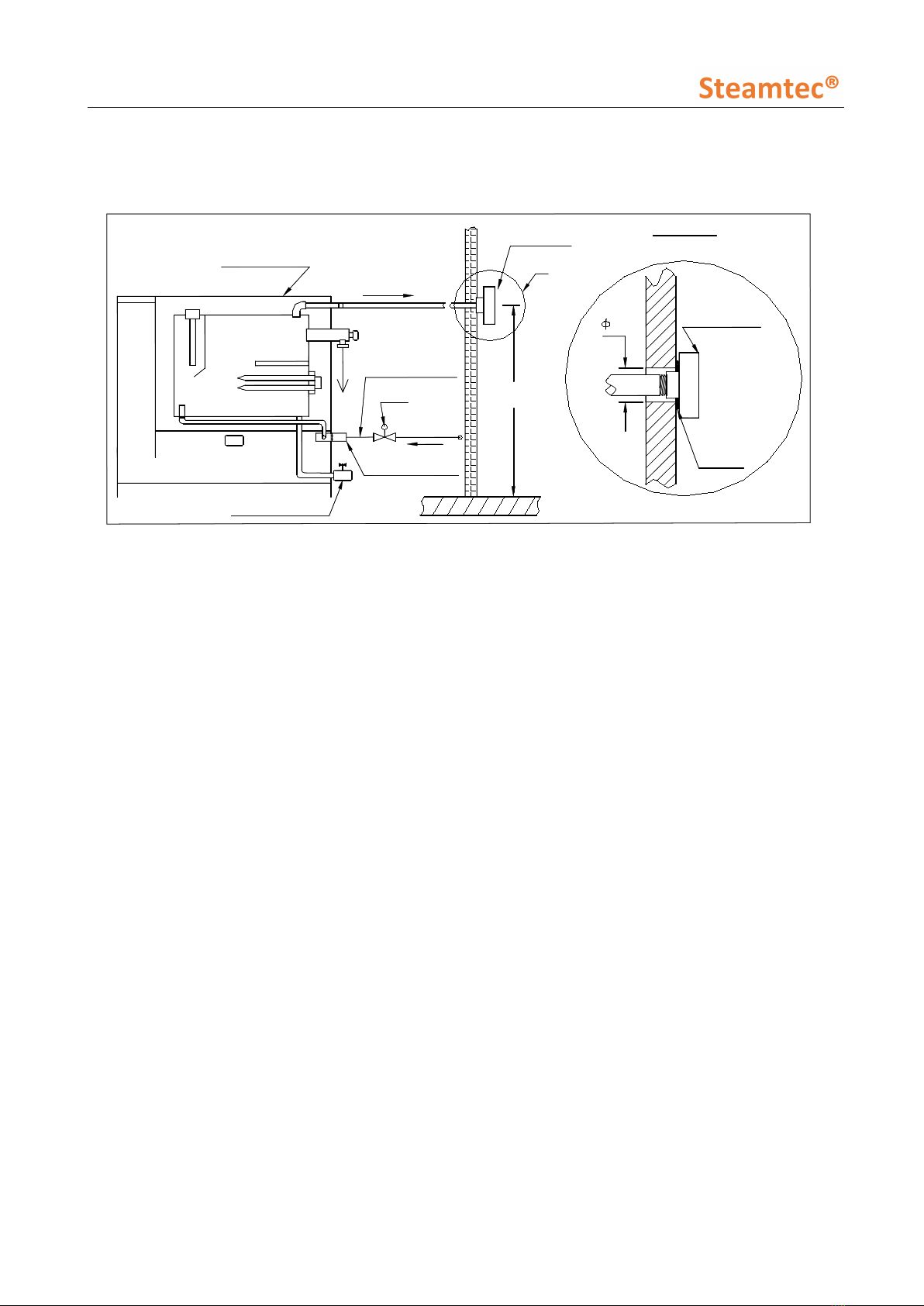
6.5. Installation of pipeline
Figure 11 3kw- 13.5kw pipe connection
Figure 12 15kw-24kw pipe connection
3kw ~ 13.5kw
①Service hole 1/2’’
②Steam outlet
3kw~6kw: 1/2’’
7kw~13.5kw:3/4’’
③Safety valve 1/2’’
④Water inlet 1/2’’
⑤Drain outlet 3/4’’
⑥Power supply for
drain valve
15kw ~ 24kw
①Service hole 1/2’’
②Steam outlet 3/4’’
③Safety valve 1/2’’
④Water inlet 1/2’’
⑤Drain outlet 3/4’’
⑥Power supply for
drain valve
②
_________________________________________________________________________________
TOLO SAUNA info@tolosauna.com www.tolosauna.com
17
i. Water Inlet:
First connect the water magnetizer (if applicable) to the water inlet solenoid valve. Then please
use a 1/2’’ flexible stainless steel hose to connect the other side of the water magnetizer and the
water supply pipeline. Do not connect to metal water supply pipeline directly which may damage
the water inlet valve.
Attention: Only use cold water supply.
ii. Drain Outlet
Please use 3/4’’ copper pipe or stainless steel pipe to connect the drain outlet and the drain
pipeline of the house. The drain pipeline should be installed with small angle so as to help
residual water in the steam generator flow to the drain pipe.
Attention: Don’t use locking pliers to over tight the drain pipe connection. Just make sure it
without leakage under Teflon tape sealing. The water come out from the steam generator will
over 100℃. Don’t use the plastic pipe/acrylic pipe/FRP pipe or other similar material pipe.
iii. Steam outlet
Please use copper or stainless steel pipe to connect the steam head and the steam outlet pipe of
the generator. The pipe should be less than 3 meters long and minimize the number of elbows,
otherwise heat isolating methods should be implemented.
For 3KW-6KW steam generator, steam outlet is 1/2’’, please AT LEAST use 1/2’’ steam pipe,
must be stainless steel pipe or copper pipe.
For 7KW-13.5KW steam generator, steam outlet is 3/4’’, please AT LEAST use 3/4’’ steam pipe,
must be stainless steel pipe or copper pipe.
For 15KW-24KW steam generator, steam outlets are TWO 3/4’’ , please AT LEAST use TWO
SEPARATE 3/4’’ steam pipes, don’t cross the two steam pipes, must be stainless steel pipe or
copper pipe.
Attention: Please MUST choose right diameter steam pipe, as if the pipe size is smaller than
our instruction, it may cause the steam generator internal pressure to increase suddenly which
may damage the steam generator and have safety risk.
iv. Safety Valve
It’s to release the pressure of steam generator, use 1/2’’ copper pipe or stainless steel pipe to
connect the safety valve and the drain pipeline of the house. Please don’t block it.
v. Steam Head
The steam head should be about 300mm from the ground and at least 150mm from customer
seats. Please apply silicone glue on the steam pipe nipple and back of the steam head, and then
screw the steam head on to the steam pipe nipple. Please refer to figure 13, the Aromatherapy
reservoir should face upwards.
_________________________________________________________________________________
TOLO SAUNA info@tolosauna.com www.tolosauna.com
18
vi. Service hole
Can be used as maintenance hole or another steam outlet 1/2''.How to do maintenance, please
refer to Chapter Warranty And Services.
Steam head
Steam generator
Stean pipe
Valve
Water supply
Auto drain valve
Aromatherapy
Reservoir
Apply
silicone
here
Water magnetizer
Flexible stainless
steel hose
A
A
Steam head
300 mm
32
Figure 13
6.6. Installation of electrical circuits
Cautions
All circuits should be installed by licensed electricians and conform to local and national codes.
Power supply must be cut off before installation, maintenance and repair. Press the on/off
button on the controller can NOT cut off the power supply.
No additional power supply or wire is allowed to connect to the generator. Do NOT connect the
earth wire to the null wire.
Only the original parts and elements from our factory are allowed to be used in installation,
operation, maintenance and repair.
After the installation of the pipeline and electrical circuits, careful checking must be performed
before switch on the generator.
The generator has been carefully installed, checked and tested in factory, thus user only need to
install the power wire.
The power supply should be 215-240V or 380-415V, 50/60Hz, please refer to the nameplate of
the generator.
The selection of fuse and breaker must strictly follow the data in table 2.
Choose the suitable power wire according to table 2 and local codes.
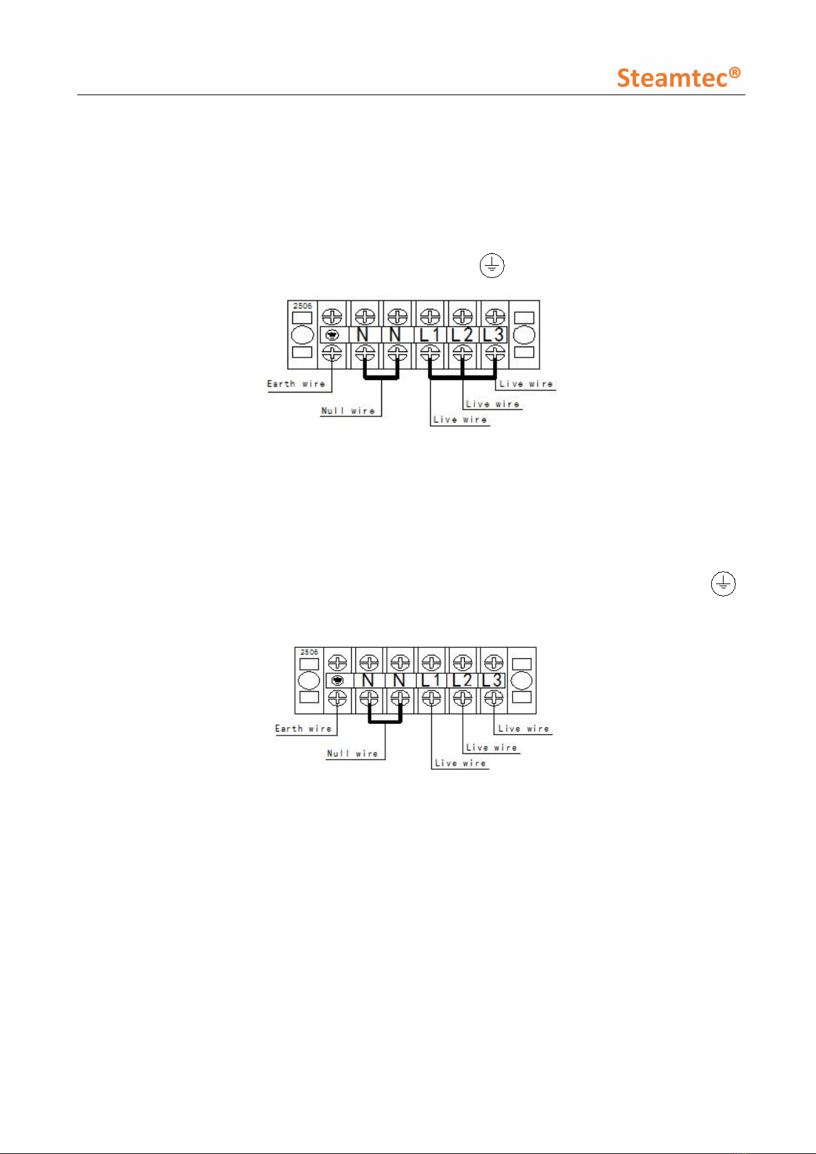
Take off the back cover of the generator, insert the 3-core (1 live, 1 null and 1 earth) power wire
(single phase, 215-240V, 50/60Hz ) or 5-core (3 lives, 1 null and 1 earth) power wire (three
phases 380-415V, 50/60Hz) into the hole at the back of the generator case and connect to the
correct terminal. (Refer to figure12-13). After that, tightening the wire terminal to prevent
accident that wire may be fall out.
_________________________________________________________________________________
TOLO SAUNA info@tolosauna.com www.tolosauna.com
19
6.6.1. Power Supply
Single phase, 215-240V,50/60Hz power supply:
Connect the live wire to the terminal labeled as “L”; connect the null wire to the terminal labeled as
“N” ; and connect the earth wire to the terminal labeled as “ ”. Please see figure 14.
Figure 14 Single phase, 215-240V
Three phases, 380-415V,50/60Hz power supply :
Connect the 3 live wires to the terminal labeled as “L1”, “L2” and “L3” respectively; connect the null
wire to the terminal labeled as “N”; and connect the earth wire to the terminal labeled as “ ”.
Please see below figure 15.
Figure 15 Three phases, 380-415V
6.6.2. Wire Diagram

_________________________________________________________________________________
TOLO SAUNA info@tolosauna.com www.tolosauna.com
20
AIO 3KW, 4KW European 215 ~240 V single phase
Figure 16
25 03
NL
term inal blocks
N1
N2L2
L1
heating element 2
NO
COM
heating element 1
O ve r-he at p ro tection
ca th ode
5 46
13
N O
C O M
Table of contents
Other Steamtec Iron manuals


